Page is loading ...

20VS8-202N
P. 1 / 4
EM-4444
5-2-55, Minamitsumori, Nishinari-ku, Osaka 557-0063 JAPAN
Phone: +81(6)6659-8201 Fax: +81(6)6659-8510 E-mail: info@m-system.co.jp
ISOLATION AMPLIFIER
(small size, input isolation, DIP type)
MODEL
20VS8-202N
INSTRUCTION MANUAL
BEFORE USE ....
Thank you for choosing M-System. Before use, check the
contents of the package you received as outlined below.
If you have any problems or questions with the product,
please contact M-System’s Sales Office or representatives.
■ PACKAGE INCLUDES:
Amplifier ....................................................................... (1)
■ MODEL NO.
Confirm that the model number described on the product is
exactly what you ordered.
■ INSTRUCTION MANUAL
This manual describes necessary points of caution when
you use this product, including installation, connection and
basic maintenance procedures.
POINTS OF CAUTION
■ POWER INPUT RATING
•Operationalvoltagerange&powerconsumption
15V DC rating: Rating ±5%, approx. 7.5mA (with no load)
■ ENVIRONMENT
•Indooruse
•Donotinstalltheunitwhereitissubjectedtocontinuous
vibration. Do not apply physical impact to the unit.
•Environmentaltemperaturemustbewithin-25to+85°C
(-13to185°F)withrelativehumiditywithin30to90%RH
in order to ensure adequate life span and operation.
■ WIRING
•Do not install cables (power supply, input and output)
close to noise sources (relay drive cable, high frequency
line, etc.).
•Do not bind these cables together with those in which
noises are present. Do not install them in the same duct.
■ INSTALLING THE MODULE
When it is installed on the printed wiring board, land diam-
eterø1.6andthrough-holeø1.0arerecommended.
■ AND ....
•Theunitisdesignedtofunctionassoonaspowerissup-
plied,however,awarmupfor10minutesisrequiredfor
satisfying complete performance described in the data
sheet.
•With voltage output, do not leave the output terminals
shortcircuited for a long time. The unit is designed to en-
dure it without breakdown, however, it may shorten ap-
propriate life duration.
CHECKING
1) Terminal wiring: Check that wiring is correctly connect-
ed according to the connection diagram.
2) Powerinputvoltage:Checkvoltageacrossthepins.
3) Input:Checkthattheinputsignaliswithin0–100%of
the full-scale.
4) Output: Check that the load resistance meets the de-
scribed specifications.
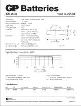
TERMINAL CONNECTIONS
■ EXTERNAL DIMENSIONS mm (inch)
max. 53.3 (2.1)
17.8 (.7)
12.7 (.5)
40.6 (1.6)
2.54 (.1)
40.6 (1.6)
max. 8.9
(.35)
min. 2.5
(.1)
17.8 (.7)
12.7 (.5)
1
2
318
22
19
38 37 36 20
0.46 (.02) dia.
20
19
18
3
2
1
Output (+)
Output COM (–)
Inverting Input
38
37
36
Feedback
Reference Voltage Source (+)
Reference Voltage Source (–)
Power Supply (–)
Input COM (–)
Non-inverting Input
22
Power Supply (+)
PIN ASSIGNMENTS

20VS8-202N
P. 2 / 4
EM-4444
5-2-55, Minamitsumori, Nishinari-ku, Osaka 557-0063 JAPAN
Phone: +81(6)6659-8201 Fax: +81(6)6659-8510 E-mail: info@m-system.co.jp
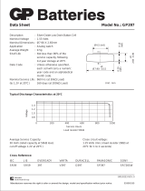
■ CONNECTION DIAGRAM
INPUT VIN
+
FEEDBACK
COM (–)
NON-INVERTING INPUT
INVERTING INPUT
REFERENCE Volt. SOURCE for INPUT
–
Note. The reference voltage source for input is common to the input COM (–)
+
+
COM (–)
–
POWER SUPPLY
APPLICATION EXAMPLES
The primary amplifier in this unit is high accurate. Installing external resistors to the inverting input (pin 3) and the feed-
back (pin 4), this unit can be used as a non-inverting or inverting amplifier.
The series resistance of the amplifier, R1+R2mustbebetween10kΩand200kΩ.
The output is proportional to the input.
The gain is 1.
E.g.0–5VDCfor0–5VDCinput.
The output is inverted from the input.
The gain is -1.
E.g.0VDCfor0VDCinputand-5V
DCfor+5VDCinput.
For a non-inverting amplication, the
output is following.
VO=(1+R1 / R2) × VIN
When R1=10kΩ,R2=10kΩ,thenthe
outputisfollowing.Thegainis2.
VO=2× VIN
38
3
■
2
1
36
37
19
18
15V DC
POWER
20
22
Non-inverting amplifier circuit: Basic example of G = 1
Non-inverting circuit G = 1
REF. Volt. SOURCE for INPUT
INPUT VIN
OUTPUT Vo
+
–
+
–
+
–
+
–
+
–
38
3
OUTPUT Vo
36
37
19
18
20
22
R1 R1
2
1
15V DC
■
Inverting amplifier circuit: Basic example of G = -1 (output is inverted from the input)
Inverting circuit G = -1
REF. Volt. SOURCE for INPUT
INPUT VIN
+
–
+
–
+
–
+
–
POWER
+
–
–
38
3
OUTPUT Vo
–
−
36
37
18
–
20
22
R2 R1
–
2
1
19
15V DC
POWER
■ Non-inverting amplifier circuit: Example of G = 1 + R1 / R2
INPUT VIN
REF. Volt. SOURCE for INPUT
Non-inverting amplifier circuit G = 1 + R
1 / R2
+
+
+
+
+

20VS8-202N
P. 3 / 4
EM-4444
5-2-55, Minamitsumori, Nishinari-ku, Osaka 557-0063 JAPAN
Phone: +81(6)6659-8201 Fax: +81(6)6659-8510 E-mail: info@m-system.co.jp
Foraninvertingamplication,theout-
put is following.
VO = -(R1 / R2) × VIN
When R1=20kΩ,R2=10kΩ,thenthe
outputisfollowing.Thegainis-2.
VO=-(20kΩ/10kΩ)× VIN=-2× VIN
+
–
38
3
–
+
+
–
36
37
19
18
+
–
20
22
+
R2 R1
–
2
1
15V DC
POWER
■ Inverting amplifier circuit: Example of G = -R1 / R2 (output is inverted from the input)
Inverting amplifier circuit G = -R
1 / R2
OUTPUT VO
INPUT VIN
REF. Volt. SOURCE for INPUT
Foranon-invertingamplicationwith
externaladjustments, when thecom-
bined resistance of the span adjust-
ment and 9 kΩ is 10 kΩ, the gain is
(1+10kΩ/R2) × VIN. With the span
adjustment(2 kΩ),theoutputiscon-
gurable.Thezeroisadjustablewith
a reference voltage source of ±16.5 V
DC
and the attenuation of 200Ωand
30kΩ.
For an inverting amplication with
externaladjustments, when thecom-
bined resistance of the span adjust-
ment and 9 kΩ is 10 kΩ, the gain is
-(10kΩ/R2) × VIN. With the span ad-
justment(2kΩ),theoutputiscong-
urable.Thezeroisadjustablewith
a
reference voltage source of ±16.5 V DC
and the attenuation of200 Ω and30
kΩ.
9kΩ
10kΩ
50kΩ
(ZERO)
2kΩ
(SPAN)
10kΩ
30kΩ
200Ω
38
3
36
37
18
20
22
1
2
■
Non-inverting amplifier circuit with external adjustments: Example of G = 2
+
–
–
+
+
–
Non-inverting amplifier circuit zero/span adjustments
INPUT V
IN
REF. Volt.
SOURCE
for INPUT
19
15V DC
POWER
OUTPUT Vo
+
–
+
–
9kΩ
10kΩ
100kΩ
(ZERO)
2kΩ
(SPAN)
10kΩ
30kΩ
200Ω
19
18
20
22
15V DC
POWER
38
3
36
37
2
1
■
Inverting amplifier circuit with external adjustments: Example of G = -1 (output is inverted from the input)
+
+
–
–
+
+
–
Inverting amplifier circuit zero/span adjustments
–
OUTPUT VO
INPUT VIN
REF. Volt.
SOURCE
for INPUT
+
–
+
–
INPUT V
IN
+
–
+Vos
–Vos
–
+
–
+
■ Non-inverting amplifier circuit: With noise filter
REF. Volt. SOURCE
for INPUT
+
–
Circuit with low-pass filter installed
on the output.

20VS8-202N
P. 4 / 4
EM-4444
5-2-55, Minamitsumori, Nishinari-ku, Osaka 557-0063 JAPAN
Phone: +81(6)6659-8201 Fax: +81(6)6659-8510 E-mail: info@m-system.co.jp
MAINTENANCE
Regular calibration procedure is explained below:
■ CALIBRATION
Warmuptheunitforatleast10minutes.Apply0%,25%,
50%, 75% and100% input signal. Checkthat the output
signal for the respective input signal remains within accu-
racy described in the data sheet.
/