Page is loading ...

Owner’s Manual
forModelP1IU-A9
PortableAirCompressor
© Inge
rsoll Rand Company
C.C.N. : 80445059
REV. :
A
DATE : MAY 2009
SAFETY
DEFIN
ITIONS______________________________________
•
DANGE
R
WILL cause DEATH, SEVERE INJURY or
substantialpropertydamage.
•
WARNI
NG
CAN cause DEATH, SEVERE INJURY or
substantialpropertydamage.
•
CAUTI
ON
WILL or CAN cause MINOR INJURY or property
damage.
GENERAL SAFETY PRECAUTIONS __________________
•
DANGE
R
INHALATION HAZARD. Will cause serious injury or death.
l
Can contain carbon monoxide or other contaminants. Ingersoll
Rand air compressors are not designed, intended or approved
for breathing air. Compressed air should not be used for
breathing air applications unless treated in accordance with
all applicable codes and regulations.
l Do not directly inhale compressed air.
l Follow precautions on container labels before spraying
materials such as paint, insecticide and weed killer.
l
Wear a respirator when spraying.
•
WARNI
NG
FLAMMABLE VAPORS. Can cause a fire or explosion and
result in serious injury or death.
l
Do not operate where flammable or explosive liquids or
vapors such as gasoline, natural gas and solvents are
present.
HAZARDOUS VOLTAGE. Can cause serious injury or death.
l
Disconnect power and bleed pressure from tank before
servicing.
l
Compressor must be connected to properly grounded circuit.
See grounding instructions in manual.
l
Do not operate compressor in wet conditions. Store indoors.
MOVING PARTS. Can cause serious injury.
l
Do not operate with guards or shields removed, damaged or
broken.
l
Machine may start automatically. Disconnect power before
servic
ing.
IMPORTANT INFORMATION! READ AND FOLLOW THESE INSTRUCTIONS. RETAIN FOR REFERENCE.
HOT SU
RFACES. Can cause serious injury. Burns may occur.
l
Do not touch the compressor pump, motor or discharge tubing
during
or shortly after operation. These parts become hot.
Allow to cool before touching.
HIGH PRESSURE AIR. Can cause serious injury.
l
Do not remove, adjust, bypass, change, modify or make
substitutions for safety/relief valves or other pressure control
related devices.
l
Do not direct air stream at body.
l
Rusted tanks can cause explosion and severe injury or death.
Drain tank daily or after each use. Drain valve located at
bottom of tank.
l
Do not over-pressurize the receiver tank or similar vessels
beyond design limits.
l
Do not use a receiver tank or similar vessels that fail to meet
the design requirements of the compressor. Contact your
distributor for assistance.
l
Do not drill into, weld or otherwise alter the receiver tank or
similar vessels.
l
Do not use air tools or attachments without first determining
the max
imum pressure recommended for that equipment.
l
Do not point air nozzles or sprayers toward anyone.
•
CAUTI
ON
RISK OF BURSTING. Can cause serious injury.
l
Use only suitable air handling parts acceptable for pressure of
not less than the maximum allowable working pressure of the
machine.
FLYING DEBRIS. Can cause serious injury to eyes.
l
Wear eye protection at all times.
NOISE HAZARD. Can cause serious injury to ears.
l
Wear ear protection at all times.
NOTE
l
Do not
remove, paint over or deface decals. Replace any
missing decals.
1
WM-Portable Air Compressor P1IU-A9
Rev.0
WM-Portable Air Compressor P1IU-A9
Printed on 9/19/13
Page 1 of 32

SPECIFICATIONS
Motor Sing
le-Phase, Induction Motor
Power Source Single-Phase, 120V AC 60 Hz
Current 15.0 A
Tank Capacity 4 gal. (15.1 l)
Maximum Pressure 135 PSI (9.3 bar)
Free Air Delivery
Lubrication Oil
PREPARATION FOR USE
SELECTIN
G A LOCATION___________________________
GENERAL. Select a clean, dry, well-lighted area with plenty of
space for proper cooling air flow and accessibility. Locate the unit
on a solid level surface at least 12 inches (30 cm) from walls.
Ensure unit is as level as possible. In order to avoid damaging
the air compressor, do not incline the unit transversely or
longitudinally more than 10°.
TEMPERATURE. Ideal operating temperatures are between
50°F and 100°F (10°C and 37.8°C).
•
CAUTION
Ne
ver operate in temperatures below 32°F
(0°C)orabove104°F(40.0°C).
HUMID AREAS. In frequently humid areas, moisture may form in
the compressor and produce sludge in the lubricant, causing
running parts to wear out prematurely. Excessive moisture is
especially likely to occur if the unit is located in an unheated area
that is subject to large temperature changes. Two signs of
excessive humidity are external condensation on the compressor
when it cools down and a “milky” appearance in petroleum
compressor lubricant. You may be able to prevent moisture from
forming in the compressor by increasing ventilation or operating
for longer intervals.
ATTACHMENTS ___________________________________
When attaching tools and accessories to your air compressor,
a
dhere to the following general guidelines. Contact customer
service for more information.
•
CAUTION
If you
will be using Ingersoll Rand “All-Season
Select” synthetic lubricant, all downstream
attachments must be compatible. Refer to the
following material compatibility list. If there are
incompatible materials present, or if there are
materials not included in the list, contact
customerservice.
Suitable:
Viton®, Teflon®, Epoxy (Glass Filled), Oil Resistant Alkyd,
Fluorosilicone, Fluorocarbon, Polysulfide, 2-Component Urethane,
Nylon, Delrin®, Celcon®, High Nitrile Rubber (Buna N. NBR more than
36% Acrylonitrile), Polyurethane, Polyethylene, Epichlorohydrin,
Polyacrylate, Melamine, Polypropylene, Baked Phenolics, Epoxy,
Modified Alkyds
(® indicates trademark of DuPont Corporation)
NotRecommended:
Neoprene, Natural Rubber, SBR Rubber, Acrylic Paint, Lacquer, Varnish,
Polystyrene, PVC, ABS, Polycarbonate, Cellulose Acetate, Low Nitrile
Rubber (Buna N. NBR less than 36% Acrylonitrile), EPDM, Ethylene
Vinyl Acetate, Latex, EPR, Acrylics, Phenoxy, Polysulfones, Styrene
Acrylonitrile (San), Butyl
GENERAL REQUIREMENTS. The attac
hments, piping, fittings,
receiver tank, etc. must be certified safe for at least the
maximum working pressure of the unit. Use hard-welded or
threaded steel or copper pipes, cast iron fittings and hoses that
are certified safe for the unit’s discharge pressure and
temperature. DO NOT USE PVC PLASTIC. Use pipe thread
sealant on all threads, and make up joints tightly to prevent air
leaks.
CONDENSATE DISCHARGE. Condensate must be disposed of
in accordance with local, state, and federal laws and regulations.
NOTE All compr
essed air systems generate
condensate which accumulates in any drain
point (e.g. tanks, filters, drip legs, aftercoolers,
dryers). This condensate contains lubricating
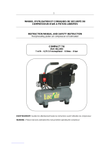
C
E
F
P
B
G
J
A
N
O
H
I
M
K
D
L
M
A TANK PRESSURE GAUGE
B LINE PRE
SSURE GAUGE
C TANK
D RUBBER BUMPER
E SAFETY / RELIEF VALVE
F ON/OFF SWITCH
G MOTOR/PUMP
H INTAKE FILTER
I CYLINDER
J OIL DIPSTICK
K CASING COVER
L OIL DRAIN CAP
M TANK DRAIN
N PRESSURE REGULATOR KNOB
O QUICK CONNECT
P LIFTING HANDLE
@ 90 PSI (6.2 bar) 4.3 CFM (125 l/min)
@ 135 PSI (9.3 bar) 3.2 CFM (90 l/min)
2
WM-Portable Air Compressor P1IU-A9
Rev.0
WM-Portable Air Compressor P1IU-A9
Printed on 9/19/13
Page 2 of 32

oil and/or substances which may be regulated
and must be disposed
of in accordance with
local,state,andfederallawsandregulations.
ELECTRICAL WIRING & GROUNDING ________________
•
WARN
ING
Any electrical installation and service required
should be performed by a qualified electrician
who is familiar with all applicable local, state
andfederallawsandregulations.
NOTE This
product should be connected to a
grounded,metallic,permanentwiringsystem.
NOTE Inge
rsoll Rand recommends the use of a
dedicated 20 AMP outlet for this air
compressor. A 15 AMP outlet may be sufficient
forsomeapplications.
GENERAL. The motor rating, as shown on the motor nameplate,
and the power supply must have compatible voltage, phase and
hertz characteristics.
WIRE SIZE. The electrical wiring between the power supply and
electric motor varies according to motor horsepower. Power
leads must be adequately sized to protect against excessive
voltage drop during start-up. Information for selecting the proper
wire size and securing connections should be provided with the
motor. If not, refer to the National Electric Code (NEC) or
applicable local, state and federal laws and regulations. If other
electrical equipment is connected to the same circuit, the total
electrical load must be considered in selecting the proper wire
size. DO NOT USE UNDERSIZE WIRE.
FUSES. Refer to the National Electric Code to determine the
proper fuse or circuit breaker rating required. When selecting
fuses, remember the momentary starting current of an electric
motor is greater than its full load current. Time-delay or
“slow-blow” fuses are recommended.
GROUNDING. The unit is equipped with a power cord having a
grounding wire and an appropriate grounding plug. The plug
must be used with an outlet that has been installed and grounded
in accordance with all local codes and ordinances. The outlet
must have the same configuration as the plug. DO NOT USE AN
ADAPTER.
•
WARN
ING
In the event of a short circuit, grounding
reduces the risk of shock by providing an
escape for the electric current. The unit must
beproperlygrounded.
•
DANG
ER
Improper installation of the grounding plug can
result in a risk of electric shock. If repair or
replacement of the cord or plug is necessary,
do not connect the grounding wire to either flat
blade terminal. The wire with insulation having
an outer surface that is green with or without
yellowstripesisthegroundingwire.
Check with a qualified electrician or service technician if the
grounding instructions are not completely understood, or if in
doubt as to whether the product is properly grounded. Do not
modify the plug provided; if it will not fit the outlet, have the
proper outlet installed by a qualified electrician.
This product is for use on a nominal 115-volt circuit and has a
grounding plug that looks like the plug illustrated below. Make
sure the product is connected to an outlet having the same
configuration as the plug. No adapter should be used with this
product.
EXTENSION CORDS. It is preferable to use extra air hose
instead of an extension cord to avoid voltage drop and power
loss to the motor, and to prevent overheating. If an extension
cord must be used, ensure it meets the following criteria:
l
Three wire cord with a three blade grounding plug, and a
three
slot outlet that will accept the plug on the unit.
l
Good condition.
l
No longer than 50 feet.
l
12 gauge or larger.
NOTE Wire
size increases as gauge number
decreases. For example, 10 AWG and 8 AWG
wire is acceptable, whereas 14 or 16 AWG are
NOTacceptable.
COMPRESSOR LUBRICATION_______________________
•
CAUT
ION
Do not operate without lubricant or with
inadequate lubricant. Ingersoll Rand is not
responsible for compressor failure caused by
inadequatelubrication.
NOTE The compressor is shipped
without oil in the
crankcase. A bottle of oil is supplied. Follow
theoilfillingproceduresinthismanual.
NOTE A plastic plug is
inserted in the oil fill opening.
Remove this plug and replace it with the oil
dipstickprovidedbeforeoperatingtheunit.
SYNTHETIC LUBRICANT. We recommend Ingersoll Rand
“All-Season Select” synthetic lubricant.
ALTERNATE LUBRICANTS. You may use a petroleum-based
lubricant that is premium quality, does not contain detergents,
contains only anti-rust, anti-oxidation, and anti-foam agents as
additives, has a flashpoint of 440°F (227°C) or higher, and has
an auto-ignition point of 650°F (343°C) or higher.
See the petroleum lubricant viscosity table below. The table is
intended as a general guide only. Heavy duty operating
conditions require heavier viscosities. Refer specific operating
conditions to your dealer for recommendations.
Temperature
AroundUnit
Viscosity@
100°F(37.8°C)
Viscosity
Grade
°F(°C) SUS(Centistokes) ISO(SAE)
<40 (4.4)
150(32) 32(10)
40 - 80 (4.4 - 26.7)
500(110) 100(30)
80 - 125 (26.7 - 51.0)
750(165) 150(40)
If you use a petroleum-based compressor lubricant at start-up
and d
ecide to convert to Ingersoll Rand “All-Season Select”
synthetic lubricant later on, the compressor valves must be
3
WM-Portable Air Compressor P1IU-A9
Rev.0
WM-Portable Air Compressor P1IU-A9
Printed on 9/19/13
Page 3 of 32

thoroughly decarbonized and the crankcase must be flushed
befo
re conversion.
OPERATION
PRIO
R TO OPERATION _____________________________
1. Ensurethatthepowersourcetobeutilizedconformstothe
powersourcerequirementsspecifiedontheproductnameplate.
SeeELECTRICALWIRING&GROUNDINGformore
information.
2. Ensurethattheleverofthepressureswitchisinthe“OFF”
position.Iftheplugisconnectedtoaoutletwhiletheknobisin
the“ON/AUTO”position,thecompressorwillstartoperating
immediatelyandcancauseseriousinjury.
3. Useascrewdriverorsimilartooltoremovetheplasticshipping
capfromtheoilfillhole.
4. Pour“All-SeasonSelect”orotherapprovedoilintotheoilfillhole
tothelevelindicatedonthedipstickprovided.See
COMPRESSORLUBRICATIONformoreinformation.
5. Installthedipstickintheoilfillhole.
6. Inserttheplugintotheoutlet.Ifthepoweroutletonlyloosely
acceptstheplug,theoutletmustberepaired.Contactaqualified
electricianforrepairservice.Theuseofafaultyoutletmay
causeoverheating,resultinginaserioushazard.
•
WARN
ING
Drain the tank to release air pressure before
removingthedipstick.
•
WARN
ING
Make sure the air vent in the dipstick is free
from debris. If the air vent is blocked, pressure
can build in the crankcase and cause damage
to the compressor and possible personal
injury.
7. Positionthecompressoronafirm,levelsurfaceinawell
ventilatedareaawayfrompotentiallyexplosivevapors,gasesor
otheragents.SeeSELECTINGALOCATIONformore
information.
•
CAUT
ION
To avoid damaging the compressor, do not
allow the unit to be tilted more than 10° when
operating.
•
CAUT
ION
Never operate in temperatures below 32°F
(0°C)orabove104°F(40°C).
STARTING ________________________________________
•
WARN
ING
Wear appropriate personal eye and ear
protectionduringuse.
1. Inserttheplugintotheoutletandstartthecompressorbyturning
thepressureswitchleverto“ON/AUTO”.
•
CAUT
ION
Do not stop or start the compressor by use of
the plug. Always use the lever located on the
pressureswitch.
The operation of the compressor is automatic and is controlled
by the pressure switch. The pressure switch stops the
compressor when the pressure in the air tank reaches the
maximum level and restarts the compressor when the air
pressure drops to the restart level.
The motor includes a thermal protection switch which stops the
compressor if the temperature becomes too high. If the switch is
tripped, the compressor will restart only after the reset button is
pushed. See THERMAL OVERLOAD PROTECTION for more
information.
2. Adjustthepressuretotherequiredlevelbyturningthepressure
regulatorknobclockwisetoincreasethepressureand
counterclockwisetodecreasethepressure.
A pressure gauge is provided to indicate when the required
pressure is reached.
•
WARN
ING
Prior to using air tools or attachments, check
the manufacturer’s maximum pressure rating
for that equipment. The compressor outlet
pressure must be regulated to never exceed
the maximum pressure rating of the tools or
attachments.
STOPPING & STORAGE ____________________________
1. Turnthepressureswitchleverto“OFF”.
2
. Unplugthecordfromthepowersourceandsecurethecord
tightlyaroundthehandle.
3. Slowlyopenthetankdrainvalvetodepressurizethetankandto
emptyallaccumulatedwater.Keepyourfaceandeyesaway
fromthedrainvalve.
•
WARN
ING
If the tank becomes corroded, there is a risk of
breakdown. If the tank is not drained, water will
corrode and weaken the air tank causing a risk
of air tank rupture. Drain the tank daily or after
fourhoursofuse.
4. Store the compressor in a clean, dry location.
A = Maximum Oil Level
B = Mi
nimum Oil Level
A = “ON/AUTO”
B = “O
FF”
4
WM-Portable Air Compressor P1IU-A9
Rev.0
WM-Portable Air Compressor P1IU-A9
Printed on 9/19/13
Page 4 of 32

THERMAL OVERLOAD PROTECTION ________________
The t
hermal protector operates to stop the motor when a problem
occurs. If the motor should stop during operation, proceed as
follows.
1. Turnthepressureswitchlevertothe“OFF”positionand
disconnecttheplugfromthereceptacle.
2. Iftheextensioncorddoesnotconformtotheproper
specifications,replacewithsuitableextensioncord.Ifthe
capacityofthepowersupplyisinsufficient,increasethepower
supplycapacitytoremovethecauseofaflowofexcessive
current(over-current).
3. Waitapproximately5minutes,thenpresstheresetbuttonofthe
thermalprotector.
4. Ifthemotorstillstopsduringoperation,pleasecallforservice.
A = Thermal Protector
5
WM-Portable Air Compressor P1IU-A9
Rev.0
WM-Portable Air Compressor P1IU-A9
Printed on 9/19/13
Page 5 of 32

MAINTENANCE
•
WARN
ING
Unplug the unit, release air pressure from the
tank and allow the unit to cool before
performingmaintenance.
•
WARN
ING
Wear appropriate personal eye and ear
protectionduringmaintenance.
NOTE All c
ompressed air systems contain
maintenance parts (e.g. lubricating oil, filters,
separators) which are periodically replaced.
These used parts may be, or may contain,
substances that are regulated and must be
disposed of in accordance with local, state,
andfederallawsandregulations.
NOTE Take note of
the positions and locations of
parts during disassembly to make reassembly
easier. The assembly sequences and parts
illustratedmaydifferforyourparticularunit.
NOTE Any service operations not
included in this
section should be performed by an authorized
IngersollRandservicerepresentative.
ROUTINE MAINTENANCE SCHEDULE
DailyorBefore
EachOperation
l
Check lubricant level. Fill as needed.
l
Drain receiver tank condensate. Open the
manual drain valve and collect and dispose
of condensate accordingly.
l
Check for unusual noise and vibration.
l
Ensure guards and covers are securely in
place.
l Ensure area around compressor is free
from rags, tools, debris, and flammable or
explosive materials.
Weekly/50Hours
l
Inspect air filter element. Clean or replace
if nec
essary.
Monthly
l
Inspect for air leaks. Squirt soapy water
around joints during compressor operation
and watch for bubbles.
l
Check tightness of screws and bolts.
Tighten as needed.
l
Clean exterior.
6/100*
l
Change petroleum lubricant while
crankcase is warm.
12/300*
l
Change synthetic lubricant while crankcase
is warm.
l
Replace filter element.
* indicates months/operating hours, whichever occurs first.
INTAKE FILTER CLEANING _________________________
Remo
ve the intake filter every 50 hours or once a week and
clean the inside of the intake filter and the filter element with
compressed air. Turn the wing nut counterclockwise to
disassemble intake filter.
•
WARN
ING
Never clean filter element with a flammable
liquidorsolvent.
•
CAUT
ION
Donotoperatewithouttheintakefilter.
NOTE Replace the filter element
when it becomes
dirty.
TANK DRAINING __________________________________
Drain both tanks daily or after 4 hours of use. Open drain cock
and tilt compressor to empty accumulated water.
COMPRESSOR PUMP OIL CHANGE _________________
•
CAUT
ION
Do not operate without lubricant or with
inadequate lubricant. Ingersoll Rand is not
responsible for compressor failure caused by
inadequatelubrication.
•
CAUT
ION
Overfilling with oil will cause premature
compressorfailure.Donotoverfill.
1. Withinthefirst50hoursofoperation,completelyreplacetheoilof
thepumpingelement.Unfastentheoildraincaponthecasing
cover,drainalltheoil,andscrewthecapbackon.
2. PourAll-SeasonSelectorotherapprovedoilintotheholeofthe
dipsticktothelevelindicatedonthedipstick.See“Preparationfor
Use”sectionforlubricantrecommendations.
3. Checktheoillevelofthepumpingelementevery50hoursor
onceaweek.
4. Changetheoilaccordingtothefollowingintervals:
Mineraloil=100hoursorevery6months.
AllSeasonSelect=300hoursorevery12months.
TANK INSPECTION ________________________________
The life of an air receiver tank is dependent upon several fact
ors
in
cluding, but not limited to, operating conditions, ambient
environments, and the level of maintenance. The exact effect of
these factors on tank life is difficult to predict; therefore, Ingersoll
Rand recommends that you schedule a certified tank inspection
within the first five years of compressor service. To arrange a
tank inspection, contact the nearest Ingersoll Rand Customer
Center or distributor, or call 1-800-AIR SERV.
If the tank has not been inspected within the first 10 years of
compressor service, the receiver must be taken out of service
until it has passed inspection. Tanks that fail to meet
requirements must be replaced.
•
WARN
ING
Failure to replace a rusted air receiver tank
could result in air receiver tank rupture or
explosion, which could cause substantial
property damage, severe personal injury, or
death. Never modify or repair tank. Obtain
replacementfromservicecenter.
A
A = Filter Element
6
WM-Portable Air Compressor P1IU-A9
Rev.0
WM-Portable Air Compressor P1IU-A9
Printed on 9/19/13
Page 6 of 32

PARTS LIST
2
6
3
15
4
1
9
5
17
16
10
8
7
13
14
22
20
23
25
28
18
19
20
21
23
17
16
27
22
14
13
12
11
9
8
5
4
3
29
15
26
24
7
10
1
2
6
11
12
19
18
15
21
PUMP ______________________________________________
REF.
N
O.
PART NO. DESCRIPTION QTY.
1 23360068 HEAD - CYLINDER 1
2 23360084 SET - ALLEN BOLT 4
3 23360092 GASKET - EXHAUST ELBOW 1
4 23360100 ELBOW - EXHAUST 1
5 23360118 BOLT - ALLEN HEAD 2
6 23360126 FILTER - AIR INLET 1
7 23360134 ELEMENT - AIR INLET FILTER 1
8 23360142 ASSEMBLY - INLET & EXHAUST VALVE 1
9 23360159 CYLINDER 1
10 23360167 SET - DOUBLE HEAD SCREW 2
11 23360175 GASKET - CYLINDER 1
12 23360183 SET - PISTON RING 1
13 23360191 SET - PISTON 1
14 23360209 ROD 1
15 23360217 CRANKSHAFT & BALANCER 1
16 23360225 SET - MOTOR 1
17 23360233 GASKET - FRONT COVER 1
18 23360241 COVER - FRONT 1
19 23360258 BOLT 4
20 23360266 PLUG 1
21 23360274 SET - DIPSTICK 1
22 23360282 SET - CENTRIFUGAL SWITCH 1
23 23360290 COOLING FAN 1
24 23360308 SHROUD 1
25 23360316 BOLT 6
26 23360324 STARTING CAPACITOR 1
27 23360332 RUNNING CAPACITOR 1
28 23360340 THERMAL PROTECTOR 1
29 23360357 AUTOMATIC RELIEF VALVE 1
30 23369655 GASKET - HEAD 1
31 23369663 GASKET - VALVE ASSEMBLY/CYLINDER 1
TANK_______________________________________________
REF.
NO.
PARTNO. DESC
RIPTION QTY.
1 23360365 TANK - AIR 1
2 23360373 VALVE - BALL 1
3 23360381 SET - RUBBER PAD 4
4 23360399 GRIP 1
5 23360407 VALVE - PRESSURE RELIEF 1
6 23360431 BODY SEAT BLOCK 6
7 23360449 VALVE - CHECK 1
8 23360456 ELBOW - UNLOADING 1
9 23360464 TUBE - UNLOADING 1
10 23360472 EXHAUST SOFT TUBE 1
11 23360480 TANK SEATING 1
12 23360498 SET - HEXAGON BOLT 4
13 23360506 SWITCH - PRESSURE 1
14 23360514 BUSHING - STRAIN RELIEF 2
15 23360522 PLUG 3
16 23360530 TUBE - SOFT 1
17 23360548 ELBOW - EXHAUST 1
18 23360555 GAUGE - PRESSURE 2
19 23360563 SET - MOTOR FOOT BOLT 4
20 23360571 REGULATOR 1
21 23360589 COUPLER - QUICK CONNECT (FEMALE) 2
22 23360597 CABLE 1
23 23360605 CABLE - POWER 1
7
WM-Portable Air Compressor P1IU-A9
Rev.0
WM-Portable Air Compressor P1IU-A9
Printed on 9/19/13
Page 7 of 32

REPAIR KITS ___________________________________________________________________________________________
DESC
RIPTION PART NO. KIT CONTENTS
GASKET KIT 23369739 QTY. (1) EXHAUST ELBOW GASKET — PART NO. 23360092 (REF. NO. 3)
QTY. (1) CYLINDER GASKET — PART NO. 23360175 (REF. NO. 11)
QTY. (1) FRONT COVER GASKET — PART NO. 23360233 (REF. NO. 17)
QTY. (1) HEAD GASKET — PART NO. 23369655 (REF. NO. 30)
QTY. (1) VALVE ASSEMBLY/CYLINDER GASKET — PART NO. 23369663 (REF. NO. 31)
VALVE ASSEMBLY KIT 23369754 QTY. (1) INLET & EXHAUST VALVE — PART NO. 23360142 (REF. NO. 8)
QTY. (1) HEAD GASKET — PART NO. 23369655 (REF. NO. 30)
QTY. (1) VALVE ASSEMBLY/CYLINDER GASKET — PART NO. 23369663 (REF. NO. 31)
PISTON RING KIT 23369762 QTY. (1) CYLINDER GASKET — PART NO. 23360175 (REF. NO. 11)
QTY. (1) PISTON RING SET — PART NO. 23360183 (REF. NO. 12)
QTY. (2) HEAD GASKET — PART NO. 23369655 (REF. NO. 30)
QTY. (2) VALVE ASSEMBLY/CYLINDER GASKET — PART NO. 23369663 (REF. NO. 31)
START-UP & MAINTENANCE
KIT
23369721 QTY. (1) 0.5 LITER OF OIL — PART NO. 97338131
QTY. (1) AIR INTAKE FILTER ELEMENT — PART NO. 23360134 (REF. NO. 7)
COMPLETE PUMP 23369747 REF. NO. 1-31
ALL SEASON SELECT SYNTHETIC LUBRICANT ____________________________________________________________
DESC
RIPTION PART NO.
0.5 LITER OF OIL 97338131
8
WM-Portable Air Compressor P1IU-A9
Rev.0
WM-Portable Air Compressor P1IU-A9
Printed on 9/19/13
Page 8 of 32

Questions? Parts? Service?
1-800 AIR S
ERV
Retain your receipt as proof of purchase in the event of a claim under warranty.
9
WM-Portable Air Compressor P1IU-A9
Rev.0
WM-Portable Air Compressor P1IU-A9
Printed on 9/19/13
Page 9 of 32

10
WM-Portable Air Compressor P1IU-A9
Rev.0
WM-Portable Air Compressor P1IU-A9
Printed on 9/19/13
Page 10 of 32

Manual del Propietario
paraelModeloP1IU-A9
CompresordeAirePortátil
© Inge
rsoll Rand Company
C.C.N. : 80445059
REV. :
A
DATE : MAY 2009
SEGURIDAD
DEFIN
ICIONES ____________________________________
•
PELIG
RO PRODUCIRÁLA MUERTE,LESIONESGRAVESo
dañosconsiderablesalapropiedad.
•
ADVER
TENCIA PUEDEproducirLA MUERTE,LESIONESGRAVESo
dañosconsiderablesalapropiedad.
•
PRECA
UCIÓN CAUSARÁoPUEDEcausarLESIONESMENORESo
dañosalapropiedad.
PRECAUCIONES GENERALES DE SEGURIDAD _______
•
PELIG
RO
ADMISIÓN DE AIRE. Causará lesiones graves o la muerte.
l
Puede contener monóxido de carbono y otros contaminantes.
Los compresores de aire Ingersoll Rand no están diseñados,
tienen por objeto o están aprobados para aire respirable. Aire
comprimido No se de usar para aplicaciones de respiración
de aire salvo que se trate de acuerdo con todos los códigos y
regulaciones aplicables.
l
No inhale directamente el aire comprimido.
l
Siga las precauciones contenidas en las etiquetas antes de
v
aporizar materiales tales como pinturas, insecticidas y
herbicidas.
l
Use un respirador y gafas de seguridad cuando realice tareas
d
e vapo
rización.
•
ADVER
TENCIA
VAPORES INFLAMABLES. Pueden causar un fuego o una
explosión y un resultado en lesión seria o en muerte.
l
No opere el equipo donde estén presentes líquidos o vapores
inflamables o explosivos tales como gasolina, gas natural o
solventes.
TENSIÓN PELIGROSA. Puede causar lesiones graves o la
muerte.
l
Desconecte la alimentación y purgue la presión del tanque
antes de efectuar un servicio.
l
El compresor debe estar conectado en forma adecuada a un
circuito a tierra. Vea las instrucciones del conexionado a
tierra en el manual.
l
No opere el compresor en condiciones mojadas. Almacénelo
en el interior.
PARTES MÓVILES. Pueden causar lesiones graves.
l
No lo opere con las protecciones quitadas.
l
La máquina puede encenderse de manera automática.
D
escon
ecte la alimentación antes de efectuar un servicio.
INFORMACIÓN IMPORTANTE. LEA Y SIGA ESTAS INSTRUCCIONES. CONSERVE PARA LA REFERENCIA.
SUPER
FICIES CALIENTES. Pueden causar lesiones graves.
Las que
maduras pueden ocurrir.
l
No toque la bomba, motor o tubo de descarga del compresor
durante o inmediatamente después de la operación. Estas
partes pueden estar calientes.
AIRE A ALTA PRESIÓN. La derivación, modificación o
eliminación de las válvulas de seguridad/alivio puede causar
lesiones graves o la muerte.
l
No quite, ajuste, realice derivaciones, cambie, modifique o
efectúe cambios de válvulas de seguridad/alivio u otros
dispositivos relacionados con el control de la presión.
l
No dirija la corriente de aire hacia el cuerpo.
l
Los tanques oxidados pueden producir una explosión o
causar lesiones graves o la muerte. Drene el tanque
diariamente o después de cada uso. La válvula de drenaje se
encuentra en la parte inferior del tanque.
l
No sobre-presurice el tanque receptor o contenedores
similares más que los límites de diseño.
l No use un tanque receptor o contendor similar que no cumpla
con los requerimientos de diseño del compresor. Contáctese
con su distribuidor para obtener asistencia.
l
No perfore, suelde ni altere de manera alguna el tanque
recept
or o contenedores similares.
l
No use herramientas neumáticas o accesorios sin primero
determinar la presión máxima recomendada para ese equipo.
l
No apunte las boquillas o rociadores de aire hacia ninguna
persona.
•
PRECA
UCIÓN
RIESGO DE ESTALLIDO. Puede causar lesión seria.
l Use sólo piezas de manejo de aire adecuadas para una
presión no inferior a la presión de trabajo máxima permitida de la
máquina.
RUINA DE VUELO. Puede causar lesión seria a los ojos.
l Protección de ojo del desgaste siempre.
PELIGRO DEL RUIDO. Puede causar lesión seria a los oídos.
l Protección auditiva del desgaste siempre.
NOTA
l
No qui
te, pinte o deforme las calcomanías. Reemplace las
calcomanías faltantes.
11
WM-Portable Air Compressor P1IU-A9
Rev.0
WM-Portable Air Compressor P1IU-A9
Printed on 9/19/13
Page 11 of 32

ESPECIFICACIONES
Motor Mo
tor de inducción monofásico
Fuente de alimentación Monofásico, 120V AC 60 Hz
Corriente 15,0 A
Capacidad del tanque 4 gal. (15,1 l)
Presión máxima 135 PSI (9,3 bar)
Entrega de aire libre
Lubricación Aceite
PREPARACIÓN PARA USO
SELECC
IÓN DE UNA UBICACIÓN____________________
GENERAL. Seleccione un área limpia, seca y bien iluminada
con espacio suficiente para un flujo de enfriamiento de aire
apropiado y accesibilidad. Ubique la unidad en una superficie de
nivel sólido por lo menos a 12 pulgadas (30 cm) de las paredes.
Asegúrese de que la unidad esté los más nivelada posible. Para
evitar daños en el compresor de aire, no incline la unidad de
manera trasversal o longitudinal a más de 10.
TEMPERATURA. Las temperaturas ideales de operación se
encuentran entre 50F y 100F (10C y 37,8C).
•
PRECAU
CIÓN Nuncaopereentemperaturaspordebajode32F
(0C)oporsobre104F(40,0C).
ÁREAS HÚMEDAS. En áreas frecuentemente húmedas, se
puede formar humedad en el compresor y producir lodo en el
lubricante, con el resultado del desgaste prematuro de las partes
de operación. La humedad excesiva ocurre especialmente si la
unidad se ubica en un área no calentada que está sujeta a
grandes cambios de temperatura. Dos signos de humedad
excesiva son la condensación externa en el compresor cuando
se enfría y una apariencia lechosa en el lubricante de compresor
de petróleo. Puede evitar que se forme humedad en el
compresor con el incremento de ventilación u operación por
intervalos más largos.
UNIONES _________________________________________
Cuando se unen herramientas y accesorios a su compresor de
a
ire, refiérase a los siguientes lineamientos generales.
Contáctese con el servicio de atención al cliente para mayor
información.
•
PRECAU
CIÓN SiestáutilizandolubricantesintéticoIngersollRand
All-SeasonSelect,todaslasunionesdesalida
debensercompatibles.Refiérasealasiguientelista
decompatibilidaddematerial.Siexistieran
materialesincompatiblespresentes,osihay
materialesnoincluidosenestalista,contáctesecon
elserviciodeatenciónalcliente.
Apropiado:
Viton®, Teflón®, Epoxy (llenado con vidrio), resistente al aceite Alkyd,
Fluorosilicona, Fluorocarbono, Polisulfuros, uretano de dos compuestos,
Nylon, Delrin®, Celcon®, Goma con alto Contenido de Nitrilo (Buna N.
NBR más que 36% Acrilonitrilo), Poliuretano, Polietileno, Epicloroidrin,
Poliacrilato, Melamina, Polipropileno, Fenólico Sólido, Resina Epoxi,
Alquidos modificados
(® indica marca de DuPont Corporation)
No se recomienda:
Neopreno, Goma Natural, Goma SBR, Pintura Acrílica, Laca,
Barniz,Poliesterino, PVC, ABS, Policarbonato, Acetato de Celulosa, Nitrilo
Bajo, Goma (Buna N. NBR menos que 36% de Acrilonitrilo), EPDM,
Etileno de Vinilo Acetato, Látex, EPR, Acrílicos, Resina Fenólica,
Polisulfuros, Estireno Acrilonitrilo (San), Butilo
REQUISITOS GENERALES. Las uni
ones, cañerías, accesorios;
tanque de recepción, etc., deben certificarse por lo menos en
cuanto a la seguridad de la presión de operación máxima de la
unidad. Use soldadura dura o acero roscado o tubos de cobre,
accesorios de fundición de hierro y mangueras que estén
certificadas como seguras para la presión de descarga y la
temperatura de las unidades. NO UTILICE PLÁSTICO PVC.
Utilice sellado de rosca en las cañerías en las roscas, y ajuste
las juntas bien para evitar la filtración de aire.
DESCARGA DE CONDENSADO. El condensado se debe
desecharse de conformidad con las leyes y regulaciones locales,
estatales y federales.
C
E
F
P
B
G
J
A
N
O
H
I
M
K
D
L
M
A MANÓMETRO DEL TANQUE
B MANÓM
ETRO DE LÍNEA
C TANQUE
D PARAGOLPE DE GOMA
E VÁLVULA DE SEGURIDAD / ALIVIO
F INTERRUPTOR DE ENCENDIDO/APAGADO
G MOTOR/BOMBA
H FILTRO DE ADMISIÓN
I CILINDRO
J VARILLA DE ACEITE
K CUBIERTA DE ENTUBADO
L TAPA DE DRENAJE DE ACEITE
M TANQUE DE DRENAJE
N PERILLA DEL REGULADOR DE PRESIÓN
O CONEXIÓN RÁPIDA
P PALANCA DE LEVANTAMIENTO
@ 90 PSI (6,2 bar) 4.3 CFM (125 l/min)
@ 135 PSI (9,3 bar) 3.2 CFM (90 l/min)
12
WM-Portable Air Compressor P1IU-A9
Rev.0
WM-Portable Air Compressor P1IU-A9
Printed on 9/19/13
Page 12 of 32

NOTA Todoslossistemasdeairecomprimidogeneran
condensaciónqueseacumulaencualquierpunto
dedrenaje(porejemplo,t
anques,filtros,patasde
escurrimiento,enfriadorposterior,secadores).Este
condensadocontieneaceitelubricantey/o
sust
anciasquepuedenserreguladasysedeben
desechardeconformidadconlasleyesy
regulacioneslocales,estatalesyfederales.
CABLEADO ELÉCTRICO Y CONEXIÓN A TIERRA ______
•
ADVE
RTENCIA Lasinstalacioneseléctricasyserviciosrequeridos
deberíanrealizarseporunelectricistacalificadoque
estéfamiliarizadoconlasleyesyregulaciones
locales,estatalesyfederalesvigentes.
NOTA Esteproductodeberíaconectarseaunsistemade
cableadopermanente,metálicoyconconexióna
tierra.
NOTA IngersollRandrecomiendaelusodeunasalidade
20AMP dedicadaparaestecompresordeaire.Una
salidade15AMP puedesersuficienteparaalgunas
aplicaciones.
G
ENERAL. La calificación del motor, como se muestra en la
placa del motor, y el suministro de energía deben tener un
voltaje compatible, características de fase y hertz.
TAMAÑO DE CABLE. El cableado eléctrico entre el suministro
de energía y el motor eléctrico varía de conformidad con la
fuerza del motor. Los conductores de energía deben tener un
tamaño adecuado para brindar protección contra caídas de
voltaje excesivas durante el encendido. Información para elegir
el tamaño apropiado de cable y asegurar las conexiones debería
estar provisto con el motor. De lo contrario, refiérase al Código
Nacional Eléctrico (NEC, por sus siglas en inglés) o las leyes y
regulaciones locales, estatales y federales vigentes. Si otro
equipo eléctrico está conectado al mismo circuito, la carga
eléctrica total debe considerarse en la selección del tamaño
apropiado del cableado. NO UTILICE CABLE DE MENOR
CALIBRE.
FUSIBLES. Refiérase al Código Nacional Eléctrico para
determinar el fusible adecuado o la calificación de interruptor de
circuito requerido. Cuando selecciona fusibles, recuerde que la
corriente de encendido momentánea de un motor eléctrico es
mayor que su corriente de carga total. Se recomiendan fusibles
de fusión lenta o acción retardada.
CONEXIÓN A TIERRA. La unidad está equipada con un cable
de alimentación que tiene un cable a tierra con un enchufe a
tierra adecuado. El enchufe debe usarse con una salida que
haya sido instalada y conectada a tierra de conformidad con
códigos y ordenanzas locales. La salida debe tener la misma
configuración que el enchufe. NO UTILICE UN ADAPTADOR.
•
ADVE
RTENCIA Encasodecortocircuito,laconexiónatierra
reduceelriesgodeelectrocutarseyaqueproveeun
escapeparalacorrienteeléctrica.Estaunidaddebe
estaradecuadamenteconectadaatierra.
•
PELI
GRO Lainstalacióninadecuadadelenchufeatierra
puedetenercomoresultadoriesgode
electrocutarse.Sifueranecesarialareparacióno
reemplazodelenchufeocable,noconecteelcable
atierraacualquieradelasterminalesdepunta
plana.Elcableconaislamientoconunasuperficie
desalidaqueesverdeconosinrayasamarillases
elcabledeconexiónatierra.
Verifique con un electricista calificado o técnico de servicio si las
instrucciones de conexión a tierra no han sido completamente
entendidas, o si tiene dudas sobre si el el producto está
conectado a tierra adecuadamente. No modifique el enchufe
provisto; si no encastra en la salida, haga instalar la salida
adecuada por un electricista calificado.
Este producto es para uso en un circuito nominal de 115 voltios y
tiene un enchufe de conexión a tierra que se parece al enchufe
graficado a continuación. Asegúrese de que el producto esté
conectado a una salida que tiene la misma configuración que el
enchufe. No debería utilizarse un adaptador con este producto.
CABLES DE EXTENSIÓN. Es preferible utilizar una manguera
adicional de aire en lugar de un cable de extensión para evitar
caídas de voltaje y pérdida de fuerza del motor, y evitar el
sobrecalentamiento. Si se debe usar un cable de extensión,
asegúrese de que cumpla con los siguientes requisitos:
l
Cable de tres conductores con un enchufe de tres puntas con
c
onex
ión a tierra, y una salida de tres ranuras que aceptará
el enchufe en la unidad.
l
Buena condición.
l
No más largo que 50 pies.
l
Calibre 12 o mayor.
NOTA Eltamañodelcableaumentaenlamedidaenqueel
númerodecalibredisminuye.Porejemplo,se
acept
auncablede10AWGy8A
WG,mientrasque
NOseaceptauncablede14o16AWG.
LUBRICACIÓN DE COMPRESOR ____________________
•
PREC
AUCIÓN Nolohagafuncionarsinlubricanteoconun
lubricanteinadecuado.IngersollRandnose
responsabilizaporlafalladelcompresorcausada
porelusodeunlubricanteinadecuado.
NOTA Elcompresorseenvíasinaceiteenelcigüeñal.Se
proveeunabotelladeaceite.Sigaelprocedimiento
dellenadodeaceiteenestemanual.
NOTA Seinsertaunenchufeplásticoenlaaberturade
llenadodeaceite.Retireesteenchufeyreemplácelo
conlavarilladeaceiteprovist
aantesdehacer
funcionarlaunidad.
LUBR
ICANTE SINTÉTICO. Le recomendamos el lubricante
sintético Ingersoll Rand All-Season Select.
LUBRICANTES ALTERNATIVOS. Puede utilizar un lubricante a
base de petróleo que sea de primera calidad, no contenga
detergentes, y que sólo contenga anticorrosivo, antioxidante y
antiespuma como aditivos, con un punto de inflamación de
440°F (227°C) o mayor, y cuente con un punto de encendido de
650°F (343°C) o mayor.
Véase la tabla de viscosidad del lubricante de petróleo a
continuación. La tabla sólo se utiliza como guía general. Las
condiciones de funcionamiento de alta resistencia requieren
viscosidades más pesadas. Consulte con su distribuidos las
condiciones de funcionamiento a fin de recibir recomendaciones.
Temperatura
AlrededordelaUnidad
Viscosidada
100F(37,8°C)
Viscosidad
Grado
°F(°C) SUS(Centistokes) ISO(SAE)
<40 (4,4)
150(32) 32(10)
40 - 80 (4,4 - 26,7)
500(110) 100(30)
80 - 125 (26,7 - 51,0)
750(165) 150(40)
Si utiliza un lubricante para su compresor basado en petróleo en
e
l
e
n
cendido y decide utilizar un lubricante sintético Ingersoll
13
WM-Portable Air Compressor P1IU-A9
Rev.0
WM-Portable Air Compressor P1IU-A9
Printed on 9/19/13
Page 13 of 32

Rand All-Season Select posteriormente, las válvulas del
comp
resor debe ser descarbonizadas por completo y el cigüeñal
debe ser lavado antes de la conversión a otro lubricante.
FUNCIONAMIENTO
ANTE
S DEL FUNCIONAMIENTO _____________________
1. Asegúresedequelafuentedeenergíaaserutilizadasea
compatibleconlosrequisitosdefuentedeenergíaespecificados
enlaplacadelproducto.VéaseCABLEADOELÉCTRICOY
CONEXIÓNATIERRAparamayorinformación.
2. Asegúresedequelapalancadelinterruptordepresiónestéenla
posiciónOFF(APAGADO).Sielenchufeseconectaaunasalida
mientraslaperillaestáenlaposiciónON/AUTO
(ENCENDIDO/AUTO),elcompresorcomenzaráafuncionar
inmediatamenteypuedecausarlesionesgraves.
3. Utiliceundestornilladoroherramientasimilarparasacarlatapa
deenvíodeplásticodelorificiodellenadodeaceite.
4. ViertaAll-SeasonSelectuotroaceiteaprobadoenelorificiode
llenadodeaceitehastaelnivelindicadoenlavarillaprovista.
VéaseLUBRICACIÓNDELCOMPRESORparamayor
información.
5. Instalelavarillaenelorificiodellenadodeaceite.
6. Silasalidadealimentaciónaceptasinajustarelenchufe,la
salidadebeserreparada.Contácteseconunelectricista
calificadoparaelserviciodereparación.Elusodeunasalida
defectuosapuedecausarsobrecalentamiento,ycomo
consecuencia,unpeligroserio.
•
ADVE
RTENCIA Dreneeltanqueparaliberarlapresióndeaireantes
deretirarlavarilla.
•
ADVE
RTENCIA Asegúresedequelaventilacióndeaireenlavarilla
estélibrederesiduos.Silaventilacióndeaireestá
bloqueada,sepuedeformarpresiónenelcigüeñal
ycausardañosalcompresoryposibleslesiones
personales.
8. Coloqueelcompresorenunasuperficiefirme,niveladaenun
áreabienventiladaalejadadepotencialesvaporesexplosivos,
gasesuotrosagentes.VéaseSELECCIÓNDEUNA
UBICACIÓNparamayorinformación.
•
PREC
AUCIÓN Paraevitardañosenelcompresor,nopermitaque
launidadseinclinemásde10cuandofunciona.
•
PREC
AUCIÓN Nuncaopereentemperaturaspordebajode32°F
(0°C)oporsobre104°F(40,0°C).
INICIO____________________________________________
•
ADVE
RTENCIA Utiliceprotecciónojosyauditivaadecuadadurante
suuso.
1. Inserteelenchufeenlasalidayhagafuncionarelcompresor
posicionandolapalancadelinterruptordepresiónenON/AUTO.
•
PREC
AUCIÓN Nodetenganienciendaelcompresormedianteel
usodelenchufe.Siempreutilicelapalancaubicada
enelinterruptordepresión.
El funcionamiento del compresor es automático y se controla con
el interruptor de presión. El interruptor de presión detiene el
compresor cuando la presión en el tanque de aire alcanza el
nivel máximo y reinicia el compresor cuando la presión de aire
disminuye al nivel de reinicio.
El motor incluye un interruptor de protección térmica que detiene
al compresor si la temperatura se torna muy alta. Si el interruptor
se desconecta, el compresor se reiniciará sólo luego de
presionar el botón de reinicio. Véase PROTECCIÓN DE
SOBRECARGA TÉRMICA para mayor información.
2. Ajustelapresiónalnivelrequeridomediantelaposicióndela
perilladelreguladordepresiónenelsentidohorariopara
incrementarlapresiónyensentidoinversoalhorariopara
disminuirlapresión.
Se provee un manómetro para indicar cuándo la presión
requerida se alcanza.
•
ADVE
RTENCIA Verifiquelacapacidaddepresiónmáximadel
fabricantesparaclavadoras,engrampadorasy
accesorios.Lasalidadepresióndelcompresor
deberegularseparanuncaexcederlacapacidadde
presiónmáximadelasclavadoras,engrampadotas
yaccesorios.
DETENCIÓN Y ALMACENAJE _______________________
1. PosicioneelinterruptordepresiónenOFF.
2
. Desenchufeelcabledelafuentedealimentación.Asegurela
cablefirmementealrededordelamanija.
3. Lentamenteabralaválvuladedrenajedeltanqueparavaciaral
aguaacumulada.Mantengasucarayojosalejadosdelaválvula
dedrenaje.
•
ADVE
RTENCIA Sieltanquetuviesecorrosión,puedellegara
romperse.Sieltanquenoestádrenado,elagua
producirácorrosiónydebilitaráeltanquedeaire
conelresultadodequepuedehaberriesgode
roturadetanquedeaire.Dreneeltanque
diariamenteoluegodecuatrohorasdeuso.
4. Guarde el compresor en una localización limpia y seca.
A = Max.
B = Mi
n.
A = ON/AUTO (ENCENDIDO/AUTO)
B = OF
F (APAGADO)
14
WM-Portable Air Compressor P1IU-A9
Rev.0
WM-Portable Air Compressor P1IU-A9
Printed on 9/19/13
Page 14 of 32

PROTECCIÓN DE SOBRECARGA TÉRMICA ___________
El pr
otector térmico funciona para parar el motor cuando ocurre
un problema. Si el motor debiera detenerse durante el
funcionamiento, proceda de la siguiente manera.
1. Posicionelapalancadelinterruptordepresiónenlaposición
OFFydesconecteelenchufedelreceptáculo.
2. Sielalarguenocumpleconlasespecificacionesadecuadas,
reempláceloporunalargueadecuado.Silacapacidaddela
alimentacióneléctricaesinsuficiente,incrementelacapacidadde
alimentacióneléctricaparaeliminarlacausadeflujoexcesivode
corriente(sobre-corriente).
3. Espereaproximadamente5minutos,luegopresioneelbotónde
reiniciodelprotectortérmico.
4. Sielmotoraúnsedetienedurantesufuncionamiento,llamepara
queloinspeccionen.
A = El protector térmico
15
WM-Portable Air Compressor P1IU-A9
Rev.0
WM-Portable Air Compressor P1IU-A9
Printed on 9/19/13
Page 15 of 32

MANTENIMIENTO
•
ADVE
RTENCIA Desenchufelaunidad,liberelapresióndeairedel
tanqueypermitaquelaunidadseenfríeantesde
realizarelmantenimiento.
•
ADVE
RTENCIA Utiliceprotecciónojosyauditivaadecuadadurante
mantenimiento.
NOTA Todoslossistemasdeairecomprimidocontienen
partesdemantenimiento(porejemplo,aceitede
lubricación,filtros,separadores)quesereemplazan
periódicamente.Est
aspartesusadaspuedenser,o
puedencontener,sustanciasqueseanreguladaso
debandesecharsedeconformidadconleyesy
regulacioneslocales,estatalesyfederales.
NOTA Tomenotadelasposicionesyubicacionesdelas
partesduranteeldesarmadop
ararealizarel
rearmadofácilmente.Lassecuenciasdearmadoy
laspartesilustradaspuedendiferirdesuunidad
particular.
NOTA Lostrabajosdeservicionoincluidosenesta
seccióndeberánserrealizadosporun
represent
antedeservicioautorizadoIngersollRand.
CRON
OGRAMA DE MANTENIMIENTO DE
RUTINA
Diariamenteo
antesdecada
funcionamiento
l
Verifique el nivel de lubricante. Llénelo en
la medida necesaria.
l
Condensado del tanque receptor de
drenaje. Abra la válvula de drenaje manual
y recolecte y elimine el condensado según
corresponda.
l
Verifique las vibraciones y ruidos extraños.
l Asegúrese de que las protecciones y
c
ubiertas estén en su lugar.
l
Asegúrese de que el área alrededor del
compr
esor esté libre de trapos,
herramientas, desechos y materiales
inflamables o explosivos.
Semanalmente/50
horas
l Inspeccione el elemento de filtro de aire.
L
ímpielo o reemplácelo si fuera necesario.
Mensualmente
l
Inspeccione las pérdidas de aire. Salida a
chorros de agua con jabón alrededor de las
juntas durante el funcionamiento del
compresor y observe la presencia de
burbujas.
l
Inspeccione el ajuste de los tornillos y
p
ernos. Ajústelos, si corresponde.
l
Limpie el exterior.
6/100*
l
Cambie el lubricante de petróleo mientras
el cigüeñal esté caliente.
12/300*
l
Cambie el lubricante sintético mientras el
c
igüeñal esté caliente.
l
Reemplace el elemento de filtro.
* indica meses/horas de funcionamiento, lo que ocurra primero.
LIMPIEZA DEL FILTRO DE ADMISIÓN ________________
Reti
re el filtro de admisión cada 50 horas o una vez por semana
y limpie el interior del filtro de admisión y el elemento de filtro
con aire comprimido. Gire la tuerca de mariposa en sentido
contrario al horario para desarmar el filtro de admisión.
•
ADVE
RTENCIA Nuncalimpieelelementodefiltroconunsolventeo
líquidoinflamable.
•
PREC
AUCIÓN Nolohagafuncionarsinelfiltrodeadmisión.
NOTA Reemplaceelelementodefiltrocuandoseensucie.
DREN
AJE DEL TANQUE ___________________________
Drene ambos tanques de manera diaria o luego de 4 horas de
uso. Abra las válvulas de drenaje e incline el compresor para
vaciar el agua que se haya acumulado.
CAMBIO DE ACEITE _______________________________
•
PREC
AUCIÓN Nofuncionesinellubricanteoconellubricante
inadecuado.Lacompañíanoesresponsabledela
faltadecompresorcausadaporlalubricación
inadecuada.
•
PREC
AUCIÓN Lasobrecargaconaceitecausaráfallasprematuras
delcompresor.Nosobrecargue.
1. Dentrodelasprimeras50horasdefuncionamiento,reemplace
completamenteelaceitedelelementodebombeo.Desajustela
tapadedrenajedeaceiteenlacubiertadeentubado,drenetodo
elaceiteyatornillenuevamentelatapa.
2. ViertaAll-SeasonSelectuotroaceiteaprobadoenelorificiode
delavarillahastaelnivelindicadoenlamisma.Véasela
preparaciónparaUselasecciónparalasrecomendacionesde
usodelubricantes.
3. Verifiqueelniveldeaceitedelelementodebombeocada50
horasounavezporsemana.
4. Cambieelaceitedeconformidadconlossiguientesintervalos:
Aceitemineral=100horasocada6meses.
AllSeasonSelect=300horasocada12meses.
INSPECCIÓN DEL TANQUE _________________________
La vida útil de un tanque receptor de aire depende de varios
facto
res inclusive, entre otros, condiciones de funcionamiento,
condiciones del medio ambiente, y nivel de mantenimiento. El
efecto exacto de estos factores en la la vida útil del tanque es
difícil de predecir; por consiguiente, Ingersoll Rand recomienda
que programe una inspección certificada del tanque dentro de
los primeros cinco años de servicio del compresor. Para realizar
una inspección del tanque, contáctese con el proveedor de
servicio autorizado más cercano.
Si el tanque no ha sido inspeccionado dentro de los primeros 10
años de servicio del compresor, el receptor debe dejarse de usar
hasta que se apruebe la inspección. Deben reemplazarse los
tanques que no reúnen las requisitos.
•
ADVE
RTENCIA Encasodequenosereemplaceuntanquereceptor
deaireoxidadosepuedeproducirunaexplosióno
roturadeltanquereceptordeaire,loquepuede
causarundañoimportanteasupropiedad,lesiones
gravesolamuerte.Nuncamodifiqueorepareel
tanque.Obtengaelreemplazodeuncentrode
servicio.
A
A = el filtro de admisión
16
WM-Portable Air Compressor P1IU-A9
Rev.0
WM-Portable Air Compressor P1IU-A9
Printed on 9/19/13
Page 16 of 32

PARTS LIST
2
6
3
15
4
1
9
5
17
16
10
8
7
13
14
22
20
23
25
28
18
19
20
21
23
17
16
27
22
14
13
12
11
9
8
5
4
3
29
15
26
24
7
10
1
2
6
11
12
19
18
15
21
BOMBA_____________________________________________
NO.
DE
R
EF.
NO DE
PARTE
DESCRIPCIÓN CANT.
1 23360068 HEAD - CYLINDER 1
2 23360084 SET - ALLEN BOLT 4
3 23360092 GASKET - EXHAUST ELBOW 1
4 23360100 ELBOW - EXHAUST 1
5 23360118 BOLT - ALLEN HEAD 2
6 23360126 FILTER - AIR INLET 1
7 23360134 ELEMENT - AIR INLET FILTER 1
8 23360142 ASSEMBLY - INLET & EXHAUST VALVE 1
9 23360159 CYLINDER 1
10 23360167 SET - DOUBLE HEAD SCREW 2
11 23360175 GASKET - CYLINDER 1
12 23360183 SET - PISTON RING 1
13 23360191 SET - PISTON 1
14 23360209 ROD 1
15 23360217 CRANKSHAFT & BALANCER 1
16 23360225 SET - MOTOR 1
17 23360233 GASKET - FRONT COVER 1
18 23360241 COVER - FRONT 1
19 23360258 BOLT 4
20 23360266 PLUG 1
21 23360274 SET - DIPSTICK 1
22 23360282 SET - CENTRIFUGAL SWITCH 1
23 23360290 COOLING FAN 1
24 23360308 SHROUD 1
25 23360316 BOLT 6
26 23360324 STARTING CAPACITOR 1
27 23360332 RUNNING CAPACITOR 1
28 23360340 THERMAL PROTECTOR 1
29 23360357 AUTOMATIC RELIEF VALVE 1
30 23369655 GASKET - HEAD 1
31 23369663 GASKET - VALVE ASSEMBLY/CYLINDER 1
TANQUE ____________________________________________
NO.
DE
REF.
NODE
PARTE
DESCR
IPCIÓN CANT.
1 23360365 TANK - AIR 1
2 23360373 VALVE - BALL 1
3 23360381 SET - RUBBER PAD 4
4 23360399 GRIP 1
5 23360407 VALVE - PRESSURE RELIEF 1
6 23360431 BODY SEAT BLOCK 6
7 23360449 VALVE - CHECK 1
8 23360456 ELBOW - UNLOADING 1
9 23360464 TUBE - UNLOADING 1
10 23360472 EXHAUST SOFT TUBE 1
11 23360480 TANK SEATING 1
12 23360498 SET - HEXAGON BOLT 4
13 23360506 SWITCH - PRESSURE 1
14 23360514 BUSHING - STRAIN RELIEF 2
15 23360522 PLUG 3
16 23360530 TUBE - SOFT 1
17 23360548 ELBOW - EXHAUST 1
18 23360555 GAUGE - PRESSURE 2
19 23360563 SET - MOTOR FOOT BOLT 4
20 23360571 REGULATOR 1
21 23360589 COUPLER - QUICK CONNECT (FEMALE) 2
22 23360597 CABLE 1
23 23360605 CABLE - POWER 1
17
WM-Portable Air Compressor P1IU-A9
Rev.0
WM-Portable Air Compressor P1IU-A9
Printed on 9/19/13
Page 17 of 32

JUEGOS DE REPARACIÓN _______________________________________________________________________________
DESC
RIPCIÓN NO. DE
PARTE
CONTENIDOS DE LOS JUEGOS
JUEGO DE JUNTAS 23369739 CANT. (1) DE JUNTA DE CODO DE SALIDA — NO. DE PARTE 23360092 (NO. DE REF. 3)
CANT. (1) DE JUNTA DE CILINDRO — NO. DE PARTE 23360175 (NO. DE REF. 11)
CANT. (1) DE JUNTA DELANTERA DE CUBIERTA — NO. DE PARTE 23360233 (NO. DE REF. 17)
CANT. (1) DE JUNTA DE CABEZAL — NO. DE PARTE 23369655 (NO. DE REF. 30)
CANT. (1) DE ENSAMBLE DE VÁLVULA/JUNTA DE CILINDRO — NO. DE PARTE 23369663 (NO. DE REF. 31)
JUEGO DE CONJUNTO
DE VÁLVULA
23369754 CANT. (1) DE CONJUNTO DE VÁLVULA DE ADMISIÓN Y ESCAPE PARTE — NO. DE PARTE 23360142 (NO.
DE REF. 8)
CANT. (1) DE JUNTA DE CABEZAL — NO. DE PARTE 23369655 (NO.DE REF. 30)
CANT. (1) DE ENSAMBLE DE VÁLVULA/JUNTA DE CILINDRO — NO. DE PARTE 23369663 (NO. DE REF. 31)
JUEGO DE AROS DE
PISTÓN
23369762 CANT. (1) DE JUNTA DE CILINDRO — NO. DE PARTE 23360175 (NO. DE REF. 11)
CANT. (1) DE JUEGO DE ARO DE PISTÓN — NO. DE PARTE 23360183 (NO. DE REF. 12)
CANT. (2) DE JUNTA DE CABEZAL — NO. DE PARTE 23369655 (NO.DE REF. 30)
CANT. (2) DE ENSAMBLE DE VÁLVULA/JUNTA DE CILINDRO — NO. DE PARTE 23369663 (NO. DE REF. 31)
JUEGO DE
MANTENIMIENTO Y
ENCENDIDO
23369721 CANT. (1) DE 0,5 LITRO DE ACEITE NO. DE PARTE 97338131
CANT. (1) DE ELEMENTO DE FILTRO DE ADMISIÓN — NO. DE PARTE 23360134 (NO. DE REF. 7)
CONJUNTO DE
REEMPLAZO DE BOMBA
23369747 NO. DE REF. 1-31
ALL SEASON SELECT LUBRICANTES SINTÉTICOS _________________________________________________________
DESC
RIPCIÓN NO. DE
PARTE
BOTELLA DE 0,5 LITROS 97338131
18
WM-Portable Air Compressor P1IU-A9
Rev.0
WM-Portable Air Compressor P1IU-A9
Printed on 9/19/13
Page 18 of 32

¿Preguntas? Piezas? Servicio?
1-800 AIR S
ERV
Guarde su recibo para las demandas de la garantía.
19
WM-Portable Air Compressor P1IU-A9
Rev.0
WM-Portable Air Compressor P1IU-A9
Printed on 9/19/13
Page 19 of 32

20
WM-Portable Air Compressor P1IU-A9
Rev.0
WM-Portable Air Compressor P1IU-A9
Printed on 9/19/13
Page 20 of 32
/