Page is loading ...

Owner’s Manual
forModelP1IU-A9
PortableAirCompressor
© In
gersoll Rand Company
C.C.N. : 80445059
REV
. : A
DATE : MAY 2009
SAFETY
DEF
INITIONS______________________________________
•
DAN
GER
WILL cause DEATH, SEVERE INJURY or
substantialpropertydamage.
•
WAR
NING
CAN cause DEATH, SEVERE INJURY or
substantialpropertydamage.
•
CAU
TION
WILL or CAN cause MINOR INJURY or property
damage.
GENERAL SAFETY PRECAUTIONS __________________
•
DAN
GER
INHALATION HAZARD. Will cause serious injury or death.
l
Can contain carbon monoxide or other contaminants. Ingersoll
Rand air compressors are not designed, intended or approved
for breathing air. Compressed air should not be used for
breathing air applications unless treated in accordance with
all applicable codes and regulations.
l Do not directly inhale compressed air.
l Follow precautions on container labels before spraying
materials such as paint, insecticide and weed killer.
l
Wear a respirator when spraying.
•
WAR
NING
FLAMMABLE VAPORS. Can cause a fire or explosion and
result in serious injury or death.
l
Do not operate where flammable or explosive liquids or
vapors such as gasoline, natural gas and solvents are
present.
HAZARDOUS VOLTAGE. Can cause serious injury or death.
l
Disconnect power and bleed pressure from tank before
servicing.
l
Compressor must be connected to properly grounded circuit.
See grounding instructions in manual.
l
Do not operate compressor in wet conditions. Store indoors.
MOVING PARTS. Can cause serious injury.
l
Do not operate with guards or shields removed, damaged or
broken.
l
Machine may start automatically. Disconnect power before
serv
icing.
IMPORTANT INFORMATION! READ AND FOLLOW THESE INSTRUCTIONS. RETAIN FOR REFERENCE.
HOT
SURFACES. Can cause serious injury. Burns may occur.
l
Do not touch the compressor pump, motor or discharge tubing
duri
ng or shortly after operation. These parts become hot.
Allow to cool before touching.
HIGH PRESSURE AIR. Can cause serious injury.
l
Do not remove, adjust, bypass, change, modify or make
substitutions for safety/relief valves or other pressure control
related devices.
l
Do not direct air stream at body.
l
Rusted tanks can cause explosion and severe injury or death.
Drain tank daily or after each use. Drain valve located at
bottom of tank.
l
Do not over-pressurize the receiver tank or similar vessels
beyond design limits.
l
Do not use a receiver tank or similar vessels that fail to meet
the design requirements of the compressor. Contact your
distributor for assistance.
l
Do not drill into, weld or otherwise alter the receiver tank or
similar vessels.
l
Do not use air tools or attachments without first determining
the m
aximum pressure recommended for that equipment.
l
Do not point air nozzles or sprayers toward anyone.
•
CAU
TION
RISK OF BURSTING. Can cause serious injury.
l
Use only suitable air handling parts acceptable for pressure of
not less than the maximum allowable working pressure of the
machine.
FLYING DEBRIS. Can cause serious injury to eyes.
l
Wear eye protection at all times.
NOISE HAZARD. Can cause serious injury to ears.
l
Wear ear protection at all times.
NOTE
l
Do n
ot remove, paint over or deface decals. Replace any
missing decals.

SPECIFICATIONS
Motor Si
ngle-Phase, Induction Motor
Power Source Single-Phase, 120V AC 60 Hz
Current 15.0 A
Tank Capacity 4 gal. (15.1 l)
Maximum Pressure 135 PSI (9.3 bar)
Free Air Delivery
Lubrication Oil
PREPARATION FOR USE
SELECT
ING A LOCATION___________________________
GENERAL. Select a clean, dry, well-lighted area with plenty of
space for proper cooling air flow and accessibility. Locate the unit
on a solid level surface at least 12 inches (30 cm) from walls.
Ensure unit is as level as possible. In order to avoid damaging
the air compressor, do not incline the unit transversely or
longitudinally more than 10°.
TEMPERATURE. Ideal operating temperatures are between
50°F and 100°F (10°C and 37.8°C).
•
CAUTIO
N
Never operate in temperatures below 32°F
(0°C)orabove104°F(40.0°C).
HUMID AREAS. In frequently humid areas, moisture may form in
the compressor and produce sludge in the lubricant, causing
running parts to wear out prematurely. Excessive moisture is
especially likely to occur if the unit is located in an unheated area
that is subject to large temperature changes. Two signs of
excessive humidity are external condensation on the compressor
when it cools down and a “milky” appearance in petroleum
compressor lubricant. You may be able to prevent moisture from
forming in the compressor by increasing ventilation or operating
for longer intervals.
ATTACHMENTS ___________________________________
When attaching tools and accessories to your air compressor,
a
dhere to the following general guidelines. Contact customer
service for more information.
•
CAUTIO
N
If you will be using Ingersoll Rand “All-Season
Select” synthetic lubricant, all downstream
attachments must be compatible. Refer to the
following material compatibility list. If there are
incompatible materials present, or if there are
materials not included in the list, contact
customerservice.
Suitable:
Viton®, Teflon®, Epoxy (Glass Filled), Oil Resistant Alkyd,
Fluorosilicone, Fluorocarbon, Polysulfide, 2-Component Urethane,
Nylon, Delrin®, Celcon®, High Nitrile Rubber (Buna N. NBR more than
36% Acrylonitrile), Polyurethane, Polyethylene, Epichlorohydrin,
Polyacrylate, Melamine, Polypropylene, Baked Phenolics, Epoxy,
Modified Alkyds
(® indicates trademark of DuPont Corporation)
NotRecommended:
Neoprene, Natural Rubber, SBR Rubber, Acrylic Paint, Lacquer, Varnish,
Polystyrene, PVC, ABS, Polycarbonate, Cellulose Acetate, Low Nitrile
Rubber (Buna N. NBR less than 36% Acrylonitrile), EPDM, Ethylene
Vinyl Acetate, Latex, EPR, Acrylics, Phenoxy, Polysulfones, Styrene
Acrylonitrile (San), Butyl
GENERAL REQUIREMENTS. The att
achments, piping, fittings,
receiver tank, etc. must be certified safe for at least the
maximum working pressure of the unit. Use hard-welded or
threaded steel or copper pipes, cast iron fittings and hoses that
are certified safe for the unit’s discharge pressure and
temperature. DO NOT USE PVC PLASTIC. Use pipe thread
sealant on all threads, and make up joints tightly to prevent air
leaks.
CONDENSATE DISCHARGE. Condensate must be disposed of
in accordance with local, state, and federal laws and regulations.
NOTE All com
pressed air systems generate
condensate which accumulates in any drain
point (e.g. tanks, filters, drip legs, aftercoolers,
dryers). This condensate contains lubricating
C
E
F
P
B
G
J
A
N
O
H
I
M
K
D
L
M
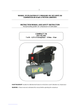
A TANK PRESSURE GAUGE
B LINE P
RESSURE GAUGE
C TANK
D RUBBER BUMPER
E SAFETY / RELIEF VALVE
F ON/OFF SWITCH
G MOTOR/PUMP
H INTAKE FILTER
I CYLINDER
J OIL DIPSTICK
K CASING COVER
L OIL DRAIN CAP
M TANK DRAIN
N PRESSURE REGULATOR KNOB
O QUICK CONNECT
P LIFTING HANDLE
2
http://air.ingersollrand.com
P1IU-A9
@ 90 PSI (6.2 bar) 4.3 CFM (125 l/min)
@ 135 PSI (9.3 bar) 3.2 CFM (90 l/min)

oil and/or substances which may be regulated
and must
be disposed of in accordance with
local,state,andfederallawsandregulations.
ELECTRICAL WIRING & GROUNDING ________________
•
WA
RNING
Any electrical installation and service required
should be performed by a qualified electrician
who is familiar with all applicable local, state
andfederallawsandregulations.
NOTE Th
is product should be connected to a
grounded,metallic,permanentwiringsystem.
NOTE In
gersoll Rand recommends the use of a
dedicated 20 AMP outlet for this air
compressor. A 15 AMP outlet may be sufficient
forsomeapplications.
GENERAL. The motor rating, as shown on the motor nameplate,
and the power supply must have compatible voltage, phase and
hertz characteristics.
WIRE SIZE. The electrical wiring between the power supply and
electric motor varies according to motor horsepower. Power
leads must be adequately sized to protect against excessive
voltage drop during start-up. Information for selecting the proper
wire size and securing connections should be provided with the
motor. If not, refer to the National Electric Code (NEC) or
applicable local, state and federal laws and regulations. If other
electrical equipment is connected to the same circuit, the total
electrical load must be considered in selecting the proper wire
size. DO NOT USE UNDERSIZE WIRE.
FUSES. Refer to the National Electric Code to determine the
proper fuse or circuit breaker rating required. When selecting
fuses, remember the momentary starting current of an electric
motor is greater than its full load current. Time-delay or
“slow-blow” fuses are recommended.
GROUNDING. The unit is equipped with a power cord having a
grounding wire and an appropriate grounding plug. The plug
must be used with an outlet that has been installed and grounded
in accordance with all local codes and ordinances. The outlet
must have the same configuration as the plug. DO NOT USE AN
ADAPTER.
•
WA
RNING
In the event of a short circuit, grounding
reduces the risk of shock by providing an
escape for the electric current. The unit must
beproperlygrounded.
•
DA
NGER
Improper installation of the grounding plug can
result in a risk of electric shock. If repair or
replacement of the cord or plug is necessary,
do not connect the grounding wire to either flat
blade terminal. The wire with insulation having
an outer surface that is green with or without
yellowstripesisthegroundingwire.
Check with a qualified electrician or service technician if the
grounding instructions are not completely understood, or if in
doubt as to whether the product is properly grounded. Do not
modify the plug provided; if it will not fit the outlet, have the
proper outlet installed by a qualified electrician.
This product is for use on a nominal 115-volt circuit and has a
grounding plug that looks like the plug illustrated below. Make
sure the product is connected to an outlet having the same
configuration as the plug. No adapter should be used with this
product.
EXTENSION CORDS. It is preferable to use extra air hose
instead of an extension cord to avoid voltage drop and power
loss to the motor, and to prevent overheating. If an extension
cord must be used, ensure it meets the following criteria:
l
Three wire cord with a three blade grounding plug, and a
thr
ee slot outlet that will accept the plug on the unit.
l
Good condition.
l
No longer than 50 feet.
l
12 gauge or larger.
NOTE Wi
re size increases as gauge number
decreases. For example, 10 AWG and 8 AWG
wire is acceptable, whereas 14 or 16 AWG are
NOTacceptable.
COMPRESSOR LUBRICATION_______________________
•
CA
UTION
Do not operate without lubricant or with
inadequate lubricant. Ingersoll Rand is not
responsible for compressor failure caused by
inadequatelubrication.
NOTE The compressor
is shipped without oil in the
crankcase. A bottle of oil is supplied. Follow
theoilfillingproceduresinthismanual.
NOTE A plastic
plug is inserted in the oil fill opening.
Remove this plug and replace it with the oil
dipstickprovidedbeforeoperatingtheunit.
SYNTHETIC LUBRICANT. We recommend Ingersoll Rand
“All-Season Select” synthetic lubricant.
ALTERNATE LUBRICANTS. You may use a petroleum-based
lubricant that is premium quality, does not contain detergents,
contains only anti-rust, anti-oxidation, and anti-foam agents as
additives, has a flashpoint of 440°F (227°C) or higher, and has
an auto-ignition point of 650°F (343°C) or higher.
See the petroleum lubricant viscosity table below. The table is
intended as a general guide only. Heavy duty operating
conditions require heavier viscosities. Refer specific operating
conditions to your dealer for recommendations.
Temperature
AroundUnit
Viscosity@
100°F(37.8°C)
Viscosity
Grade
°F(°C) SUS(Centistokes) ISO(SAE)
<40 (4.4)
150(32) 32(10)
40 - 80 (4.4 - 26.7)
500(110) 100(30)
80 - 125 (26.7 - 51.0)
750(165) 150(40)
If you use a petroleum-based compressor lubricant at start-up
an
d decide to convert to Ingersoll Rand “All-Season Select”
synthetic lubricant later on, the compressor valves must be
3
http://air.ingersollrand.com
P1IU-A9

thoroughly decarbonized and the crankcase must be flushed
be
fore conversion.
OPERATION
PR
IOR TO OPERATION _____________________________
1. Ensurethatthepowersourcetobeutilizedconformstothe
powersourcerequirementsspecifiedontheproductnameplate.
SeeELECTRICALWIRING&GROUNDINGformore
information.
2. Ensurethattheleverofthepressureswitchisinthe“OFF”
position.Iftheplugisconnectedtoaoutletwhiletheknobisin
the“ON/AUTO”position,thecompressorwillstartoperating
immediatelyandcancauseseriousinjury.
3. Useascrewdriverorsimilartooltoremovetheplasticshipping
capfromtheoilfillhole.
4. Pour“All-SeasonSelect”orotherapprovedoilintotheoilfillhole
tothelevelindicatedonthedipstickprovided.See
COMPRESSORLUBRICATIONformoreinformation.
5. Installthedipstickintheoilfillhole.
6. Inserttheplugintotheoutlet.Ifthepoweroutletonlyloosely
acceptstheplug,theoutletmustberepaired.Contactaqualified
electricianforrepairservice.Theuseofafaultyoutletmay
causeoverheating,resultinginaserioushazard.
•
WA
RNING
Drain the tank to release air pressure before
removingthedipstick.
•
WA
RNING
Make sure the air vent in the dipstick is free
from debris. If the air vent is blocked, pressure
can build in the crankcase and cause damage
to the compressor and possible personal
injury.
7. Positionthecompressoronafirm,levelsurfaceinawell
ventilatedareaawayfrompotentiallyexplosivevapors,gasesor
otheragents.SeeSELECTINGALOCATIONformore
information.
•
CA
UTION
To avoid damaging the compressor, do not
allow the unit to be tilted more than 10° when
operating.
•
CA
UTION
Never operate in temperatures below 32°F
(0°C)orabove104°F(40°C).
STARTING ________________________________________
•
WA
RNING
Wear appropriate personal eye and ear
protectionduringuse.
1. Inserttheplugintotheoutletandstartthecompressorbyturning
thepressureswitchleverto“ON/AUTO”.
•
CA
UTION
Do not stop or start the compressor by use of
the plug. Always use the lever located on the
pressureswitch.
The operation of the compressor is automatic and is controlled
by the pressure switch. The pressure switch stops the
compressor when the pressure in the air tank reaches the
maximum level and restarts the compressor when the air
pressure drops to the restart level.
The motor includes a thermal protection switch which stops the
compressor if the temperature becomes too high. If the switch is
tripped, the compressor will restart only after the reset button is
pushed. See THERMAL OVERLOAD PROTECTION for more
information.
2. Adjustthepressuretotherequiredlevelbyturningthepressure
regulatorknobclockwisetoincreasethepressureand
counterclockwisetodecreasethepressure.
A pressure gauge is provided to indicate when the required
pressure is reached.
•
WA
RNING
Prior to using air tools or attachments, check
the manufacturer’s maximum pressure rating
for that equipment. The compressor outlet
pressure must be regulated to never exceed
the maximum pressure rating of the tools or
attachments.
STOPPING & STORAGE ____________________________
1. Turnthepressureswitchleverto“OFF”.
2
. Unplugthecordfromthepowersourceandsecurethecord
tightlyaroundthehandle.
3. Slowlyopenthetankdrainvalvetodepressurizethetankandto
emptyallaccumulatedwater.Keepyourfaceandeyesaway
fromthedrainvalve.
•
WA
RNING
If the tank becomes corroded, there is a risk of
breakdown. If the tank is not drained, water will
corrode and weaken the air tank causing a risk
of air tank rupture. Drain the tank daily or after
fourhoursofuse.
4. Store the compressor in a clean, dry location.
A = Maximum Oil Level
B =
Minimum Oil Level
A = “ON/AUTO”
B =
“OFF”
4
http://air.ingersollrand.com
P1IU-A9

THERMAL OVERLOAD PROTECTION ________________
Th
e thermal protector operates to stop the motor when a problem
occurs. If the motor should stop during operation, proceed as
follows.
1. Turnthepressureswitchlevertothe“OFF”positionand
disconnecttheplugfromthereceptacle.
2. Iftheextensioncorddoesnotconformtotheproper
specifications,replacewithsuitableextensioncord.Ifthe
capacityofthepowersupplyisinsufficient,increasethepower
supplycapacitytoremovethecauseofaflowofexcessive
current(over-current).
3. Waitapproximately5minutes,thenpresstheresetbuttonofthe
thermalprotector.
4. Ifthemotorstillstopsduringoperation,pleasecallforservice.
A = Thermal Protector
5
http://air.ingersollrand.com
P1IU-A9

MAINTENANCE
•
WA
RNING
Unplug the unit, release air pressure from the
tank and allow the unit to cool before
performingmaintenance.
•
WA
RNING
Wear appropriate personal eye and ear
protectionduringmaintenance.
NOTE Al
l compressed air systems contain
maintenance parts (e.g. lubricating oil, filters,
separators) which are periodically replaced.
These used parts may be, or may contain,
substances that are regulated and must be
disposed of in accordance with local, state,
andfederallawsandregulations.
NOTE Take
note of the positions and locations of
parts during disassembly to make reassembly
easier. The assembly sequences and parts
illustratedmaydifferforyourparticularunit.
NOTE Any service
operations not included in this
section should be performed by an authorized
IngersollRandservicerepresentative.
ROUTINE MAINTENANCE SCHEDULE
DailyorBefore
EachOperation
l
Check lubricant level. Fill as needed.
l
Drain receiver tank condensate. Open the
manual drain valve and collect and dispose
of condensate accordingly.
l
Check for unusual noise and vibration.
l
Ensure guards and covers are securely in
place.
l Ensure area around compressor is free
from rags, tools, debris, and flammable or
explosive materials.
Weekly/50Hours
l
Inspect air filter element. Clean or replace
if n
ecessary.
Monthly
l
Inspect for air leaks. Squirt soapy water
around joints during compressor operation
and watch for bubbles.
l
Check tightness of screws and bolts.
Tighten as needed.
l
Clean exterior.
6/100*
l
Change petroleum lubricant while
crankcase is warm.
12/300*
l
Change synthetic lubricant while crankcase
is warm.
l
Replace filter element.
* indicates months/operating hours, whichever occurs first.
INTAKE FILTER CLEANING _________________________
Re
move the intake filter every 50 hours or once a week and
clean the inside of the intake filter and the filter element with
compressed air. Turn the wing nut counterclockwise to
disassemble intake filter.
•
WA
RNING
Never clean filter element with a flammable
liquidorsolvent.
•
CA
UTION
Donotoperatewithouttheintakefilter.
NOTE Replace the
filter element when it becomes
dirty.
TANK DRAINING __________________________________
Drain both tanks daily or after 4 hours of use. Open drain cock
and tilt compressor to empty accumulated water.
COMPRESSOR PUMP OIL CHANGE _________________
•
CA
UTION
Do not operate without lubricant or with
inadequate lubricant. Ingersoll Rand is not
responsible for compressor failure caused by
inadequatelubrication.
•
CA
UTION
Overfilling with oil will cause premature
compressorfailure.Donotoverfill.
1. Withinthefirst50hoursofoperation,completelyreplacetheoilof
thepumpingelement.Unfastentheoildraincaponthecasing
cover,drainalltheoil,andscrewthecapbackon.
2. PourAll-SeasonSelectorotherapprovedoilintotheholeofthe
dipsticktothelevelindicatedonthedipstick.See“Preparationfor
Use”sectionforlubricantrecommendations.
3. Checktheoillevelofthepumpingelementevery50hoursor
onceaweek.
4. Changetheoilaccordingtothefollowingintervals:
Mineraloil=100hoursorevery6months.
AllSeasonSelect=300hoursorevery12months.
TANK INSPECTION ________________________________
The life of an air receiver tank is dependent upon several fact
or
s
including, but not limited to, operating conditions, ambient
environments, and the level of maintenance. The exact effect of
these factors on tank life is difficult to predict; therefore, Ingersoll
Rand recommends that you schedule a certified tank inspection
within the first five years of compressor service. To arrange a
tank inspection, contact the nearest Ingersoll Rand Customer
Center or distributor, or call 1-800-AIR SERV.
If the tank has not been inspected within the first 10 years of
compressor service, the receiver must be taken out of service
until it has passed inspection. Tanks that fail to meet
requirements must be replaced.
•
WA
RNING
Failure to replace a rusted air receiver tank
could result in air receiver tank rupture or
explosion, which could cause substantial
property damage, severe personal injury, or
death. Never modify or repair tank. Obtain
replacementfromservicecenter.
A
A = Filter Element
6
http://air.ingersollrand.com
P1IU-A9

PARTS LIST
2
6
3
15
4
1
9
5
17
16
10
8
7
13
14
22
20
23
25
28
18
19
20
21
23
17
16
27
22
14
13
12
11
9
8
5
4
3
29
15
26
24
7
10
1
2
6
11
12
19
18
15
21
PUMP ______________________________________________
RE
F.
NO.
PART NO. DESCRIPTION QTY.
1 23360068 HEAD - CYLINDER 1
2 23360084 SET - ALLEN BOLT 4
3 23360092 GASKET - EXHAUST ELBOW 1
4 23360100 ELBOW - EXHAUST 1
5 23360118 BOLT - ALLEN HEAD 2
6 23360126 FILTER - AIR INLET 1
7 23360134 ELEMENT - AIR INLET FILTER 1
8 23360142 ASSEMBLY - INLET & EXHAUST VALVE 1
9 23360159 CYLINDER 1
10 23360167 SET - DOUBLE HEAD SCREW 2
11 23360175 GASKET - CYLINDER 1
12 23360183 SET - PISTON RING 1
13 23360191 SET - PISTON 1
14 23360209 ROD 1
15 23360217 CRANKSHAFT & BALANCER 1
16 23360225 SET - MOTOR 1
17 23360233 GASKET - FRONT COVER 1
18 23360241 COVER - FRONT 1
19 23360258 BOLT 4
20 23360266 PLUG 1
21 23360274 SET - DIPSTICK 1
22 23360282 SET - CENTRIFUGAL SWITCH 1
23 23360290 COOLING FAN 1
24 23360308 SHROUD 1
25 23360316 BOLT 6
26 23360324 STARTING CAPACITOR 1
27 23360332 RUNNING CAPACITOR 1
28 23360340 THERMAL PROTECTOR 1
29 23360357 AUTOMATIC RELIEF VALVE 1
30 23369655 GASKET - HEAD 1
31 23369663 GASKET - VALVE ASSEMBLY/CYLINDER 1
TANK_______________________________________________
REF.
NO.
PARTNO. DE
SCRIPTION QTY.
1 23360365 TANK - AIR 1
2 23360373 VALVE - BALL 1
3 23360381 SET - RUBBER PAD 4
4 23360399 GRIP 1
5 23360407 VALVE - PRESSURE RELIEF 1
6 23360431 BODY SEAT BLOCK 6
7 23360449 VALVE - CHECK 1
8 23360456 ELBOW - UNLOADING 1
9 23360464 TUBE - UNLOADING 1
10 23360472 EXHAUST SOFT TUBE 1
11 23360480 TANK SEATING 1
12 23360498 SET - HEXAGON BOLT 4
13 23360506 SWITCH - PRESSURE 1
14 23360514 BUSHING - STRAIN RELIEF 2
15 23360522 PLUG 3
16 23360530 TUBE - SOFT 1
17 23360548 ELBOW - EXHAUST 1
18 23360555 GAUGE - PRESSURE 2
19 23360563 SET - MOTOR FOOT BOLT 4
20 23360571 REGULATOR 1
21 23360589 COUPLER - QUICK CONNECT (FEMALE) 2
22 23360597 CABLE 1
23 23360605 CABLE - POWER 1
7
http://air.ingersollrand.com
P1IU-A9

Questions? Parts? Service?
1-800 AI
R SERV
Retain your receipt as proof of purchase in the event of a claim under warranty.
9
http://air.ingersollrand.com
P1IU-A9

10
http://air.ingersollrand.com
P1IU-A9

PARTS LIST
2
6
3
15
4
1
9
5
17
16
10
8
7
13
14
22
20
23
25
28
18
19
20
21
23
17
16
27
22
14
13
12
11
9
8
5
4
3
29
15
26
24
7
10
1
2
6
11
12
19
18
15
21
BOMBA_____________________________________________
NO
.
DE
REF.
NO DE
PARTE
DESCRIPCIÓN CANT.
1 23360068 HEAD - CYLINDER 1
2 23360084 SET - ALLEN BOLT 4
3 23360092 GASKET - EXHAUST ELBOW 1
4 23360100 ELBOW - EXHAUST 1
5 23360118 BOLT - ALLEN HEAD 2
6 23360126 FILTER - AIR INLET 1
7 23360134 ELEMENT - AIR INLET FILTER 1
8 23360142 ASSEMBLY - INLET & EXHAUST VALVE 1
9 23360159 CYLINDER 1
10 23360167 SET - DOUBLE HEAD SCREW 2
11 23360175 GASKET - CYLINDER 1
12 23360183 SET - PISTON RING 1
13 23360191 SET - PISTON 1
14 23360209 ROD 1
15 23360217 CRANKSHAFT & BALANCER 1
16 23360225 SET - MOTOR 1
17 23360233 GASKET - FRONT COVER 1
18 23360241 COVER - FRONT 1
19 23360258 BOLT 4
20 23360266 PLUG 1
21 23360274 SET - DIPSTICK 1
22 23360282 SET - CENTRIFUGAL SWITCH 1
23 23360290 COOLING FAN 1
24 23360308 SHROUD 1
25 23360316 BOLT 6
26 23360324 STARTING CAPACITOR 1
27 23360332 RUNNING CAPACITOR 1
28 23360340 THERMAL PROTECTOR 1
29 23360357 AUTOMATIC RELIEF VALVE 1
30 23369655 GASKET - HEAD 1
31 23369663 GASKET - VALVE ASSEMBLY/CYLINDER 1
TANQUE ____________________________________________
NO.
DE
REF.
NODE
PARTE
DES
CRIPCIÓN CANT.
1 23360365 TANK - AIR 1
2 23360373 VALVE - BALL 1
3 23360381 SET - RUBBER PAD 4
4 23360399 GRIP 1
5 23360407 VALVE - PRESSURE RELIEF 1
6 23360431 BODY SEAT BLOCK 6
7 23360449 VALVE - CHECK 1
8 23360456 ELBOW - UNLOADING 1
9 23360464 TUBE - UNLOADING 1
10 23360472 EXHAUST SOFT TUBE 1
11 23360480 TANK SEATING 1
12 23360498 SET - HEXAGON BOLT 4
13 23360506 SWITCH - PRESSURE 1
14 23360514 BUSHING - STRAIN RELIEF 2
15 23360522 PLUG 3
16 23360530 TUBE - SOFT 1
17 23360548 ELBOW - EXHAUST 1
18 23360555 GAUGE - PRESSURE 2
19 23360563 SET - MOTOR FOOT BOLT 4
20 23360571 REGULATOR 1
21 23360589 COUPLER - QUICK CONNECT (FEMALE) 2
22 23360597 CABLE 1
23 23360605 CABLE - POWER 1
17
http://air.ingersollrand.com
P1IU-A9

JUEGOS DE REPARACIÓN _______________________________________________________________________________
DE
SCRIPCIÓN NO. DE
PARTE
CONTENIDOS DE LOS JUEGOS
JUEGO DE JUNTAS 23369739 CANT. (1) DE JUNTA DE CODO DE SALIDA — NO. DE PARTE 23360092 (NO. DE REF. 3)
CANT. (1) DE JUNTA DE CILINDRO — NO. DE PARTE 23360175 (NO. DE REF. 11)
CANT. (1) DE JUNTA DELANTERA DE CUBIERTA — NO. DE PARTE 23360233 (NO. DE REF. 17)
CANT. (1) DE JUNTA DE CABEZAL — NO. DE PARTE 23369655 (NO. DE REF. 30)
CANT. (1) DE ENSAMBLE DE VÁLVULA/JUNTA DE CILINDRO — NO. DE PARTE 23369663 (NO. DE REF. 31)
JUEGO DE CONJUNTO
DE VÁLVULA
23369754 CANT. (1) DE CONJUNTO DE VÁLVULA DE ADMISIÓN Y ESCAPE PARTE — NO. DE PARTE 23360142 (NO.
DE REF. 8)
CANT. (1) DE JUNTA DE CABEZAL — NO. DE PARTE 23369655 (NO.DE REF. 30)
CANT. (1) DE ENSAMBLE DE VÁLVULA/JUNTA DE CILINDRO — NO. DE PARTE 23369663 (NO. DE REF. 31)
JUEGO DE AROS DE
PISTÓN
23369762 CANT. (1) DE JUNTA DE CILINDRO — NO. DE PARTE 23360175 (NO. DE REF. 11)
CANT. (1) DE JUEGO DE ARO DE PISTÓN — NO. DE PARTE 23360183 (NO. DE REF. 12)
CANT. (2) DE JUNTA DE CABEZAL — NO. DE PARTE 23369655 (NO.DE REF. 30)
CANT. (2) DE ENSAMBLE DE VÁLVULA/JUNTA DE CILINDRO — NO. DE PARTE 23369663 (NO. DE REF. 31)
JUEGO DE
MANTENIMIENTO Y
ENCENDIDO
23369721 CANT. (1) DE 0,5 LITRO DE ACEITE NO. DE PARTE 97338131
CANT. (1) DE ELEMENTO DE FILTRO DE ADMISIÓN — NO. DE PARTE 23360134 (NO. DE REF. 7)
CONJUNTO DE
REEMPLAZO DE BOMBA
23369747 NO. DE REF. 1-31
ALL SEASON SELECT LUBRICANTES SINTÉTICOS _________________________________________________________
DE
SCRIPCIÓN NO. DE
PARTE
BOTELLA DE 0,5 LITROS 97338131
18
http://air.ingersollrand.com
P1IU-A9

20
http://air.ingersollrand.com
P1IU-A9

LISTE DE PIÈCES
2
6
3
15
4
1
9
5
17
16
10
8
7
13
14
22
20
23
25
28
18
19
20
21
23
17
16
27
22
14
13
12
11
9
8
5
4
3
29
15
26
24
7
10
1
2
6
11
12
19
18
15
21
POMPE _____________________________________________
NO
RÉF.
NO DE
PIÈCE
DESCRIPTION QUAN
TITÉ
1 2
3360068 HEAD - CYLINDER 1
2 23360084 SET - ALLEN BOLT 4
3 23360092 GASKET - EXHAUST ELBOW 1
4 23360100 ELBOW - EXHAUST 1
5 23360118 BOLT - ALLEN HEAD 2
6 23360126 FILTER - AIR INLET 1
7 23360134 ELEMENT - AIR INLET FILTER 1
8 23360142 ASSEMBLY - INLET & EXHAUST VALVE 1
9 23360159 CYLINDER 1
10 23360167 SET - DOUBLE HEAD SCREW 2
11 23360175 GASKET - CYLINDER 1
12 23360183 SET - PISTON RING 1
13 23360191 SET - PISTON 1
14 23360209 ROD 1
15 23360217 CRANKSHAFT & BALANCER 1
16 23360225 SET - MOTOR 1
17 23360233 GASKET - FRONT COVER 1
18 23360241 COVER - FRONT 1
19 23360258 BOLT 4
20 23360266 PLUG 1
21 23360274 SET - DIPSTICK 1
22 23360282 SET - CENTRIFUGAL SWITCH 1
23 23360290 COOLING FAN 1
24 23360308 SHROUD 1
25 23360316 BOLT 6
26 23360324 STARTING CAPACITOR 1
27 23360332 RUNNING CAPACITOR 1
28 23360340 THERMAL PROTECTOR 1
29 23360357 AUTOMATIC RELIEF VALVE 1
30 23369655 GASKET - HEAD 1
31 23369663 GASKET - VALVE ASSEMBLY/CYLINDER 1
RÉSERVOIR D’AIR ___________________________________
NO
RÉF.
NO DE
PIÈCE
DES
CRIPTION QUAN
TITÉ
1 23360365 TANK - AIR 1
2 23360373 VALVE - BALL 1
3 23360381 SET - RUBBER PAD 4
4 23360399 GRIP 1
5 23360407 VALVE - PRESSURE RELIEF 1
6 23360431 BODY SEAT BLOCK 6
7 23360449 VALVE - CHECK 1
8 23360456 ELBOW - UNLOADING 1
9 23360464 TUBE - UNLOADING 1
10 23360472 EXHAUST SOFT TUBE 1
11 23360480 TANK SEATING 1
12 23360498 SET - HEXAGON BOLT 4
13 23360506 SWITCH - PRESSURE 1
14 23360514 BUSHING - STRAIN RELIEF 2
15 23360522 PLUG 3
16 23360530 TUBE - SOFT 1
17 23360548 ELBOW - EXHAUST 1
18 23360555 GAUGE - PRESSURE 2
19 23360563 SET - MOTOR FOOT BOLT 4
20 23360571 REGULATOR 1
21 23360589 COUPLER - QUICK CONNECT (FEMALE) 2
22 23360597 CABLE 1
23 23360605 CABLE - POWER 1
27
http://air.ingersollrand.com
P1IU-A9

REPAIR KITS ___________________________________________________________________________________________
DE
SCRIPTION No DE
PIÈCE
CONTENU
TROUSSE DE JOINTS
STATIQUES
23369739 QUANTITÉ (1) JOINT STATIQUE POUR COUDE D'ÉVACUATION No DE PIÈCE 23360092 (No RÉF. POMPE - 3)
QUANTITÉ (1) JOINT STATIQUE POUR CYLINDRE No DE PIÈCE 23360175 (No RÉF. POMPE - 11)
QUANTITÉ (1) JOINT STATIQUE DE COUVERCLE FRONTAL No DE PIÈCE 23360233 (No RÉF. POMPE - 17)
QUANTITÉ (1) JOINT STATIQUE DE TÊTE No DE PIÈCE 23369655 (No RÉF. POMPE - 30)
QUANTITÉ (1) JOINT STATIQUE D'ASSEMBLAGE DE SOUPAPE/CYLINDRE No DE PIÈCE 23369663 (No RÉF.
POMPE - 31)
ASSEMBLAGE DE
SOUPAPE
23369754 QUANTITÉ (1) ENSEMBLE DE SOUPAPES D'ADDUCTION ET ÉVACUATION No DE PIÈCE 23360142 (No RÉF.
POMPE - 8)
QUANTITÉ (1) JOINT STATIQUE DE TÊTE No DE PIÈCE 23369655 (No RÉF. POMPE - 30)
QUANTITÉ (1) JOINT STATIQUE D'ASSEMBLAGE DE SOUPAPE/CYLINDRE No DE PIÈCE 23369663 (No RÉF.
POMPE - 31)
TROUSSE DE
GARNITURE DE PISTON
23369762 QUANTITÉ (1) JOINT STATIQUE POUR CYLINDRE No DE PIÈCE 23360175 (No RÉF. POMPE - 11)
QUANTITÉ (1) ENSEMBLE DE GARNITURE DE PISTON No DE PIÈCE 23360183 (No RÉF. POMPE - 12)
QUANTITÉ (2) JOINT STATIQUE DE TÊTE No DE PIÈCE 23369655 (No RÉF. POMPE - 30)
QUANTITÉ (2) JOINT STATIQUE D'ASSEMBLAGE DE SOUPAPE/CYLINDRE No DE PIÈCE 23369663 (No RÉF.
POMPE - 31)
TROUSSE DE MISE EN
MARCHE ET
D'ENTRETIEN
23369721 QUANTITÉ (1) LITRE D'HUILE À COMPRESSEUR NO DE PIÈCE 38436721
QUANTITÉ (1) ÉLÉMENT DE FILTRE D'ASPIRATION No DE PIÈCE 23360134 (No RÉF. POMPE - 7)
TROUSSE DE
REMPLACEMENT DE
POMPE
23369747 No RÉF. POMPE 1 -31
LUBRIFIANT SYNTHÉTIQUE ALL SEASON SELECT _________________________________________________________
DE
SCRIPTION No DE
PIÈCE
BOUTEILLE DE 0,5 L 97338131
28
http://air.ingersollrand.com
P1IU-A9

30
http://air.ingersollrand.com
P1IU-A9

31
http://air.ingersollrand.com
P1IU-A9

32
http://air.ingersollrand.com
P1IU-A9
/