Page is loading ...

User Manual
Read and understand this manual before using machine.
STEEL CITY TOOL WORKS Manual Part No. OR71528
VER. 2.07
CUS
®
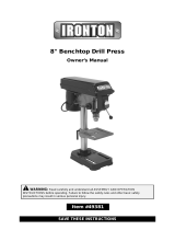
Model Number
20520
17”
DRILL
PRESS

2
THANK YOU
for purchasing your new Steel City Drill
Press. This drill press has been designed, tested, and inspect-
ed with you, the customer, in mind. When properly assem-
bled, used, and maintained, your drill press will provide you
with years of trouble free service, which is why it is backed
by one of the longest machinery warranties in the business.
This drill press is just one of many products in the Steel
City’s family of woodworking machinery and is proof of
our commitment to total customer satisfaction.
At Steel City we continue to strive for excellence each and
every day and value the opinion of you, our customer. For
comments about your drill press or Steel City Tool Works,
please visit our web site at
www.steelcitytoolworks.com
.

3
TABLE OF CONTENTS
INTRODUCTION
This user manual is intended for use by anyone working with this machine. It should be kept available
for immediate reference so that all operations can be performed with maximum efficiency and safety.
Do not attempt to perform maintenance or operate this machine until you have read and understand the
information contained in this manual.
The drawings, illustrations, photographs, and specifications in this user manual represent your machine
at time of print. However, changes may be made to your machine or this manual at any time with no
obligation to Steel City Tool Works.
INTRODUCTION
SECTION 1 Warranty .................................................................................................................................................4
SECTION 2 Product Specifications ............................................................................................................................7
SECTION 3 Accessories and Attachments ................................................................................................................7
SECTION 4 Definition of Terms..................................................................................................................................8
SECTION 5 Feature Identification ..............................................................................................................................9
SECTION 6 General Safety......................................................................................................................................10
SECTION 7 Product Safety ......................................................................................................................................13
SECTION 8 Electrical Requirements........................................................................................................................14
SECTION 9 Unpacking & Inventory..........................................................................................................................16
SECTION 10 Assembly ..............................................................................................................................................18
SECTION 11 Adjustments ..........................................................................................................................................21
SECTION 12 Operations ............................................................................................................................................25
SECTION 13 Maintenance .........................................................................................................................................28
SECTION 14 Troubleshooting ....................................................................................................................................29
SECTION 15 Parts List...............................................................................................................................................30

2 YEAR LIMITED WARRANTY
Steel City Tool Works, LLC (SCTW) warrants this SCTW machinery to be free of defects in workmanship and materials for a period
of 2 years from the date of the original retail purchase by the original owner for domestic use. Granite components are warranted for
2 years based on normal use and is void if non SCTW accessories are used that cause the break or chip. Customer must advise
SCTW within 30 days for any damage or defect found upon receipt of the product to qualify for the warranty on granite.
The warranty does not cover any product used for professional or commercial production purpose nor for industrial or educational
applications. Such cases are covered by our 1 year Limited Warranty with the Conditions and Exceptions listed below.
Conditions and exception:
Warranty applies to the original buyer only and may not be transferred. Original proof of purchase is required.
Warranty does not include failures, breakage or defects deemed after inspection by an Authorized Service Center, (ASC) or agent of,
have been directly or indirectly caused by or resulting from improper use, lack of or improper maintenance, misuse or abuse,
negligence, accidents, damage in handling or transport, or normal wear and tear of any part or component.
Additionally, warranty is void if repairs or alterations are made to the machine by an unauthorized service center without the direct
consent of SCTW
Consumables such as blades, knives, bits and sandpaper are not covered.
Wear items such as drive belt, bearings, switch, are covered for 1 year.
To file a claim of warranty or to find a service center, call toll free 877-724-8665 or email [email protected]
and
you must be able to present the original or photo copy of the sales receipt including the serial number from the machine and/or carton.
SCTW will inspect, repair or replace, at its expense and its option, any part that has proven to be defective in workmanship or
material, provided that the customer returns the product prepaid to a designated ASC and provides SCTW with a reasonable
opportunity to verify the alleged defect by inspection. SCTW will return the product or replacement at our expense unless it is
determined by us that there is no defect or that the defect resulted from causes not within the scope of our warranty in which case we
will, at your direction, dispose of or return the product. In the event you choose to have the product returned, you will be responsible
for the handling and shipping costs of the return.
SCTW furnishes the above warranties in lieu of all other warranties, express or implied. SCTW shall not be liable for any special,
indirect, incidental, punitive or consequential damages, including without limitation loss of profits arising from or related to the
warranty, the breach of any agreement or warranty, or the operation or use of its machinery, including without limitation damages
arising from damage to fixtures, tools, equipment, parts or materials, direct or indirect loss caused by and other part, loss of revenue
or profits, financing or interest charges, and claims by and third person, whether or not notice of such possible damages has been
given to SCTW. Damages or any kind for any delay by or failure of SCTW to perform its obligations under this agreement or claims
made a subject of a legal proceeding against SCTW more than one (1) year after such cause of action first arose.
The validity, construction and performance of this Warranty and any sale of machinery by SCTW shall be governed by the law of the
Commonwealth of Pennsylvania, without regard to conflicts of law’s provisions of any jurisdiction. Any action related in any way to
any alleged or actual offer, acceptance or sale by SCTW or any claim related to the performance of and agreement including without
limitation this Warranty, shall take place in the federal or state courts in Allegheny County, Pennsylvania.
Warranty registration card must be submitted to SCTW for purpose of proof within 90 days of purchase with a copy of the sales
receipt. Failure to do so will, revert the 2 year warranty to 1 year as in the terms stated above. This registration is also needed to
facilitate contact in case of a safety recall.
This warranty gives you specific legal rights and you may have other rights which vary in certain States or Provinces.
Note to user
This instruction manual is meant to serve as a guide only. Specification and references are subject to change without prior notice.
Check the website www.steelcitytoolworks.com
for updated manuals with reference to the VER# located on the front page.
LIMITED WARRANTY – ACCU-SHOP line of bench top tools
Steel City Tool Works, LLC (SCTW) warrants this SCTW ACCU-SHOP machinery to be free of defects in workmanship and materials
for a period of 2 years from the date of the original retail purchase by the original owner for domestic use.
Consumables such as blades, knives, bits and sandpaper are not covered.
Wear items such as drive belt, bearings, switch, are covered for 1 year.
The warranty does not cover any product used for professional or commercial production purpose nor for industrial or educational
applications. Such cases are covered by our 30 days Limited Warranty with the Conditions and Exceptions listed previously.
WARRANTY
4

5
WARRANTY CARD
Name ________________________________________________
Street _______________________________________________
Apt. No. ______________________________________________
City _________________________ State ______ Zip __________
Phone Number_________________________________________
E-Mail________________________________________________
Product Description:_____________________________________
Model No.: ___________________________________________
Serial No. _____________________________________________
The following information is given on a voluntary basis
and is strictly confidential.
1. Where did you purchase your STEEL CITY machine?
Store: ____________________________________________
City:______________________________________________
2. How did you first learn of Steel City Tool Works?
___ Advertisement ___ Mail Order Catalog
___ Web Site ___ Friend
___ Local Store Other_______________________
3. Which of the following magazines do you subscribe to?
___ American Woodworker ___ American How-To
––– Cabinetmaker ___ Family Handyman
___ Fine Homebuilding ___ Fine Woodworking
___ Journal of Light Construction ___ Old House Journal
___ Popular Mechanics ___ Popular Science
___ Popular Woodworking ___ Today’s Homeowner
___ WOOD ___ Woodcraft
___ WOODEN Boat ___ Woodshop News
___ Woodsmith ___ Woodwork
___ Woodworker ___ Woodworker’s Journal
___ Workbench Other_________________
4. Which of the following woodworking / remodeling shows do
you watch?
___ Backyard America ___ The American Woodworker
___ Home Time ___ The New Yankee Workshop
___ This Old House ___ Woodwright’s Shop
Other__________________________________________
5. What is your annual household income?
___ $20,000 to $29,999 ___ $30,000 to $39,999
___ $40,000 to $49,999 ___ $50,000 to $59,999
___ $60,000 to $69,999 ___ 70,000 to $79,999
___ $80,000 to $89,999 ___ $90,000 +
6. What is your age group?
___ 20 to 29 years ___ 30 to 39 years
___ 40 to 49 years ___ 50 to 59 years
___ 60 to 69 years ___ 70 + years
7. How long have you been a woodworker?
___ 0 to 2 years ___ 2 to 8 years
___ 8 to 20 years ___ over 20 years
8. How would you rank your woodworking skills?
___ Simple ___ Intermediate
___ Advance ___ Master Craftsman
9. How many Steel City machines do you own? _____________
10. What stationary woodworking tools do you own?
Check all that apply.
___ Air Compressor ___ Band Saw
___ Drill Press ___ Drum Sander
___ Dust Collection ___ Horizontal Boring Machine
___ Jointer ___ Lathe
___ Mortiser ___ Panel Saw
___ Planer ___ Power Feeder
___ Radial Arm Saw ___ Shaper
___ Spindle Sander ___ Table Saw
___ Vacuum Veneer Press ___ Wide Belt Sander
Other____________________________________________
11. Which benchtop tools do you own?
Check all that apply.
___ Belt Sander ___ Belt / Disc Sander
___ Drill Press ___ Band Saw
___ Grinder ___ Mini Jointer
___ Mini Lathe ___ Scroll Saw
___ Spindle / Belt Sander Other______________________
12. Which portable / hand held power tools do you own?
Check all that apply.
___
Belt Sander ___ Biscuit Jointer
___ Dust Collector ___ Circular Saw
___ Detail Sander ___ Drill / Driver
___ Miter Saw ___ Orbital Sander
___ Palm Sander ___ Portable Thickness Planer
___ Saber Saw ___ Reciprocating Saw
___ Router Other_______________________
13. What machines / accessories would you like to see added to the
STEEL CITY line?
____________________________________________________
____________________________________________________
14. What new accessories would you like to see added?
____________________________________________________
____________________________________________________
15. Do you think your purchase represents good value?
___Yes ___ No
16. Would you recommend STEEL CITY products to a friend?
___ Yes ___ No
17. Comments:
____________________________________________________
____________________________________________________
____________________________________________________
____________________________________________________
____________________________________________________
!
CUT HERE

FOLD ON DOTTED LINE
FOLD ON DOTTED LINE
PLACE
STAMP
HER
SteelCityToolWorks
#4 Northpoint Court
Bolingbrook, IL 60440
E
6

7
PRODUCT SPECIFICATIONS
MOTOR
Type Induction
Continuous duty HP 3/4
Amps 10/5
Volts 120/240
Phase Single
Hertz 60
RPM 1725 (no load)
PRODUCT SPECIFICATIONS
Belt type Poly-V
Pulley type Step
Belt Tensioning Motor slide
Number of speeds 16
Drill speeds 215, 310, 340, 450,
490, 510, 600, 675,
735, 750, 1200, 1380,
1500, 1850, 2035,
2720
Spindle taper #2 Morse taper
Chuck taper JT3
Chuck type Keyed
Chuck capacity 5/8”
Chuck to table dimension
maximum 24”
Chuck to base dimension 43-3/4”
Quill diameter 2”
Quill travel 6”
Quill lock Yes
ACCESSORIES AND ATTACHMENTS
There are a variety of accessories available for your Steel City Product. For more information on
any accessories associated with this and other machines, please contact your nearest Steel City
distributor, or visit our website at: www.steelcitytoolworks.com.
PRODUCT SPECIFICATIONS (cont)
Handle Operation 360 degree rotation
Motor control Industrial push button
with OFF paddle
Table size 14” wide x 14” deep
Table tilt 45° left and right
Table movement Rack and pinion
Table material Cast iron
Depth stop Yes
Depth stop type External Micro-Adjust
with Quick Set
Depth scale Yes
Column diameter 3-1/8” (80mm)
PRODUCT DIMENSIONS
Height 69”
Width 14”
Depth 27”
Weight 227 lbs.
SHIPPING DIMENSIONS
Carton type Box
Length 58”
Width 26-1/4”
Height 11-1/2”
Gross weight 251 lbs.

8
DEFINITION OF TERMS
Belt cover - Can be opened to provide access to belts,
pulleys, and speed chart.
On/Off switch - Access power to drill press or turn
power off.
Feed handles - Used to lower chuck and apply
pressure toward work piece.
Quill lock - Holds quill in predetermined position.
Keyed chuck - Key is used to loosen or tighten drilling
and sanding tools.
Table - Holds work piece.
Column - Used to support work table and drill press
head.
Base - Sits on floor, adds stability, and attaches to
column.
Depth scale - Keeps track of tool travel into work
piece.
Motor - Supplies power to drill press.
Flexible lamp - Provides light source for all operations.

9
FEATURE IDENTIFICATION
A. Belt cover
B. On/Off switch
C. Feed handles
D. Quill lock
E. Keyed chuck
F. Table
G. Column
H. Base
I. Depth scale
J. Motor
K. Flexible lamp
A
B
C
D
E
F
G
H
I
J
K

10
TO AVOID serious injury and damage to the machine,
read and follow all Safety and Operating Instructions
before assembling and operating this machine.
This manual is not totally comprehensive. It does not
and can not convey every possible safety and opera-
tional problem which may arise while using this
machine. The manual will cover many of the basic and
specific safety procedures needed in an industrial envi-
ronment.
All federal and state laws and any regulations having
jurisdiction covering the safety requirements for use of
this machine take precedence over the statements in
this manual. Users of this machine must adhere to all
such regulations.
Below is a list of symbols that are used to attract your
attention to possible dangerous conditions.
This is the international safety alert symbol. It is used
to alert you to potential personal injury hazards. Obey
all safety messages that follow this symbol to avoid
possible injury or death.
Indicates an imminently hazardous situation which, if
not avoided, WILL result in death or serious injury.
Indicates a potentially hazardous situation which, if not
avoided, COULD result in death or serious injury.
Indicates a potentially hazardous situation, if not avoid-
ed, MAY result in minor or moderate injury. It may also
be used to alert against unsafe practices.
CAUTION used without the safety alert symbol indi-
cates a potentially hazardous situation which, if not
avoided, may result in property damage.
This symbol is used to alert the user to useful informa-
tion about proper operation of the machine.
GENERAL SAFETY
DANGER
NOTICE
CAUTION
Exposure to the dust created by power sanding, saw-
ing, grinding, drilling and other construction activities
may cause serious and permanent respiratory or
other injury, including silicosis (a serious lung dis-
ease), cancer, and death. Avoid breathing the dust,
and avoid prolonged contact with dust. The dust
may contain chemicals known to the State of
California to cause cancer, birth defects or other
reproductive harm.
2. ALWAYS wear eye protection. Any machine can
throw debris into the eyes during operations,
which could cause severe and permanent eye
damage. Everyday eyeglasses are NOT safety
glasses. ALWAYS wear Safety Goggles (that
comply with ANSI standard Z87.1) when operat-
ing power tools.
WARNING
WARNING
CAUTION
!
!
!
!
!
WARNING
!
Some examples of these chemicals are:
• Lead from lead-based paints.
• Crystalline silica from bricks, cement and other
masonry products.
• Arsenic and chromium from chemically-treated
lumber.
Always operate tool in well ventilated area and pro-
vide for proper dust removal. Use a dust collection
system along with an air filtration system whenever
possible. Always use properly fitting NIOSH/OSHA
approved respiratory protection appropriate for the
dust exposure, and wash exposed areas with soap
and water.
WARNING
!
1. To avoid serious injury and damage to the machine,
read the entire User Manual before assembly and
operation of this machine.

11
4. ALWAYS wear a NIOSH/OSHA approved dust
mask to prevent inhaling dangerous dust or air-
borne particles.
8. AVOID a dangerous working environment. DO
NOT
use electrical tools in a damp environment
or expose them to rain or moisture.
9. CHILDPROOF THE WORKSHOP AREA by
removing switch keys, unplugging tools from the
electrical receptacles, and using padlocks.
3. ALWAYS wear hearing protection. Plain cotton is
not an acceptable protective device. Hearing
equipment should comply with ANSI S3.19
Standards.
WARNING
!
WARNING
!
WARNING
!
WARNING
!
11. DO NOT FORCE the machine to perform an opera-
tion for which it was not designed. It will do a safer
and higher quality job by only performing operations
for which the machine was intended.
12. DO NOT stand on a machine. Serious injury could
result if it tips over or you accidentally contact any
moving part.
13.
DO NOT store anything above or near the machine.
14. DO NOT operate any machine or tool if under the
influence of drugs, alcohol, or medication.
15.
EACH AND EVERY time, check for damaged parts
prior to using any machine. Carefully check all
guards to see that they operate properly, are not
damaged, and perform their intended functions.
Check for alignment, binding or breakage of all
moving parts. Any guard or other part that is dam-
aged should be immediately repaired or replaced.
16. Ground all machines. If any machine is supplied
with a 3-prong plug, it must be plugged into a 3-
contact electrical receptacle. The third prong is
used to ground the tool and provide protection
against accidental electric shock.
DO NOT remove
the third prong.
17. Keep visitors and children away from any machine.
DO NOT permit people to be in the immediate work
area, especially when the machine is operating.
18. KEEP protective guards in place and in working
order.
19. MAINTAIN your balance. DO NOT extend yourself
over the tool. Wear oil resistant rubber soled shoes.
Keep floor clear of debris, grease, and wax.
20. MAINTAIN all machines with care. ALWAYS KEEP
machine clean and in good working order. KEEP all
blades and tool bits sharp.
21.
NEVER leave a machine running, unattended. Turn
the power switch to the OFF position.
DO NOT
leave the machine until it has come to a complete
stop.
22. REMOVE ALL MAINTENANCE TOOLS from the
immediate area prior to turning the machine ON.
23. SECURE all work. When it is possible, use clamps
or jigs to secure the workpiece. This is safer than
attempting to hold the workpiece with your hands.
24. STAY ALERT, watch what you are doing, and use
common sense when operating any machine.
DO
NOT operate any machine tool while tired or under
the influence of drugs, alcohol, or medication. A
moment of inattention while operating power tools
may result in serious personal injury.
5.
ALWAYS keep the work area clean, well lit, and
organized. DO NOT work in an area that has slip-
pery floor surfaces from debris, grease, and wax.
6. ALWAYS unplug the machine from the electrical
receptacle before making adjustments, changing
parts or performing any maintenance.
7. AVOID ACCIDENTAL STARTING. Make sure that
the power switch is in the “OFF” position before
plugging in the power cord to the electrical
receptacle.
10.
DO NOT use electrical tools in the presence of
flammable liquids or gasses.

12
25.
USE ONLY recommended accessories. Use of
incorrect or improper accessories could cause seri-
ous injury to the operator and cause damage to the
machine. If in doubt, DO NOT use it.
26. THE USE of extension cords is not recommended
for 230V equipment. It is better to arrange the
placement of your equipment and the installed
wiring to eliminate the need for an extension cord.
If an extension cord is necessary, refer to the chart
in the Grounding Instructions section to determine
the minimum gauge for the extension cord. The
extension cord must also contain a ground wire and
plug pin.
27. Wear proper clothing,
DO NOT wear loose clothing,
gloves, neckties, or jewelry. These items can get
caught in the machine during operations and pull
the operator into the moving parts. Users must
wear a protective cover on their hair, if the hair is
long, to prevent it from contacting any moving parts.
28. SAVE these instructions and refer to them frequent-
ly and use them to instruct other users.
29. Information regarding the safe and proper operation
of this tool is also available from the following
sources:
Power Tool Institute
1300 Summer Avenue
Cleveland, OH 44115-2851
www.powertoolinstitute.org
National Safety Council
1121 Spring Lake Drive
Itasca, IL 60143-3201
American National Standards Institute
25West 43rd. St, 4th Floor
New York, NY. 10036
ANSI 01.1 Safety Requirements
For Woodworking Machines
WWW.ANSI.ORG
U.S. Department of Labor Regulations
OSHA 1910.213 Regulations
WWW.OSHA.GOV

13
1. Serious personal injury may occur if normal safety
precautions are overlooked or ignored. Accidents
are frequently caused by lack of familiarity or failure
to pay attention. Obtain advice from supervisor,
instructor, or another qualified individual who is
familiar with this machine and its operations.
2. Every work area is different. Always consider safe-
ty first, as it applies to your work area. Use this
machine with respect and caution. Failure to do so
could result in serious personal injury and damage
to the machine.
4. TO REDUCE the risk of electrical shock. DO
NOT use this machine outdoors. DO NOT
expose to rain or moisture. Store indoors in a
dry area.
9. DO NOT handle the plug or drill press with
wet hands.
WARNING
!
WARNING
!
3. Prevent electrical shock. Follow all electrical and
safety codes, including the National Electrical Code
(NEC) and the Occupational Safety and Health
Regulations (OSHA). All electrical connections and
wiring should be made by qualified personnel only.
5.
STOP using this machine, if at any time you experi-
ence difficulties in performing any operation.
Contact your supervisor, instructor or machine serv-
ice center immediately.
6. Safety decals are on this machine to warn and
direct you to how to protect yourself or visitors from
personal injury. These decals MUST be maintained
so that they are legible. REPLACE decals that are
not legible.
7. DO NOT leave the unit plugged into the electrical
outlet. Unplug the unit from the outlet when not in
use and before servicing, performing maintenance
tasks, or cleaning.
8. ALWAYS turn the power switch “OFF” before
unplugging the drill press.
PRODUCT SAFETY
10. USE accessories only recommended by Steel City.
11. DO NOT pull the drill press by the power cord.
NEVER allow the power cord to come in contact
with sharp edges, hot surfaces, oil or grease.
12.
DO NOT unplug the drill press by pulling on the
power cord. ALWAYS grasp the plug, not the cord.
13. REPLACE a damaged cord immediately. DO NOT
use a damaged cord or plug. DO NOT USE if the
drill press is not operating properly, or has been
damaged, left outdoors or has been in contact with
water.
14.
DO NOT use the drill press as a toy. DO NOT use
near or around children.
15.
CHECK all drill bits, cutting tools, sanding drums, or
other accessories for damage before installing in
the drill press chuck. Damaged items can cause
damage to the drill press and or serious injury.
16. Before leaving the drill press, LOCK the ON/OFF
switch with a padlock (not included) to prevent
unauthorized use.
17. DO NOT install or use any drill bit that exceeds
7-inches in length or that extends 6-inches below
the chuck jaws. The drill bit can suddenly bend or
break.
18. DO NOT try to drill a workpiece that is too small to
be securely held to the table or in a vise.
19. DO NOT operate this drill press until it is assembled
and installed according to the instruction manual.
20. DO NOT leave the drill press plugged into the elec-
trical outlet. Unplug the drill press from the outlet
when not in use and before servicing, changing bits
and cleaning.
21. DO NOT USE router bits, shaper cutters, circle (fly)
cutters, rotary planers or wire wheels in this drill
press.
22. FOLLOW all electrical and safety codes, including
the National Electric Code (NEC) and the
Occupational Safety and Health Regulations
(OSHA). All electrical connections and wiring should
be made by qualified personnel only.
23. LET THE CHUCK REACH FULL SPEED before
starting drill operations.
24. MAKE SURE there are no foreign objects, nails,
stones in the workpiece.
25. NEVER PERFORM LAYOUT, ASSEMBLY OR
SETUP WORK on the table/work area when the
drill press is running.

14
28.
OBTAIN ADVICE FROM YOUR SUPERVISOR,
instructor, or another qualified person if you are not
familiar with the operation of this drill press.
29.
PROPERLY SUPPORT long or wide workpiece and
clamp to the table.
30. PROPERLY SECURE the drill bit, cutting tool, or
sanding drum in the chuck before operating the drill
press.
31.
REPLACE a damaged cord immediately. DO NOT
use a damaged cord or plug.
32. SECURE the drill press to the floor or work bench.
Vibration can cause the drill press to slide, walk or
tip over. Do not attach the drill press to a mobile
base.
33. SECURE the workpiece firmly against the table.
Do not attempt to drill a workpiece that does not
have a flat surface against the table, or that is not
ELECTRICAL REQUIREMENTS
TO PREVENT electrical shock, follow all electrical and
safety codes, including the National Electrical Code
(NEC) and the Occupational Safety and Health
Regulations (OSHA). All electrical connections and
wiring should be made by qualified personnel only.
TO REDUCE the risk of electrical shock, DO NOT use
machine outdoors. DO NOT expose to rain or mois-
ture. Store indoors in a dry area.
DO NOT connect the machine to the power source
before you have completed the set up process.
DO NOT connect the machine to the power source until
instructed to do so.
The motor supplied with the drill press is a dual voltage
115/230-volt, single phase motor. The motor is wired
from the factory for 115-volt operation. To change to
230-volt operation, see CHANGING MOTOR VOLTAGE
in the adjustment section in this manual.
27.
NEVER START THE DRILL PRESS with the drill
bit, cutting tool, or sanding drum against the work-
piece. Loss of control of the workpiece can cause
serious injury.
secured by a vise. Prevent the workpiece from
rotating by clamping it to the table or by securing it
against the drill press column. Loss of control of the
workpiece can cause serious injury.
34.
SECURELY LOCK the head and table support to
the column, and the table to the table support
before operating the drill press.
35. The drill press is designed for home use or light
commercial duty ONLY.
36.
TO REDUCE THE RISK OF ELECTRICAL
SHOCK, do not use outdoors. Do not expose to
rain. Store indoors in a dry area.
37.
TURN THE DRILL PRESS OFF and unplug from
power source. Wait for the drill bit, cutting tool, or
sanding drum to come to a complete STOP before
cleaning off the table/work area, removing or secur-
ing workpiece, or changing setup.
38. USE only drill bits, cutting tools, sanding drums, or
other accessories with proper shank size recom-
mended in this instruction manual. The wrong size
shank can cause damage to the drill press and/or
serious injury.
39. USE RECOMMENDED SPEEDS for all operations.
Improper speeds may cause the machine to mal-
function causing damage to the drill press and or
serious injury.
26.
NEVER START THE DRILL PRESS BEFORE
CLEARING THE TABLE OF ALL OBJECTS (tools,
scrap pieces, etc.). Debris can be thrown at high
speed.

15
GROUNDING INSTRUCTIONS
This machine MUST BE GROUNDED while in use to
protect the operator from electric shock.
In the event of a malfunction or breakdown, GROUND-
ING provides the path of least resistance for electric
current and reduces the risk of electric shock. The plug
MUST be plugged into a matching electrical receptacle
that is properly installed and grounded in accordance
with ALL local codes and ordinances.
If a plug is provided with your machine DO NOT modify
the plug. If it will not fit your electrical receptacle, have
a qualified electrician install the proper connections to
meet all electrical codes local and state. All connections
must also adhere to all of OSHA mandates.
IMPROPER ELECTRICAL CONNECTION of the equip-
ment-grounding conductor can result in risk of electric
shock. The conductor with the green insulation (with or
without yellow stripes) is the equipment-grounding con-
ductor. DO NOT connect the equipment-grounding
conductor to a live terminal.
Check with a qualified electrician or service personnel if
you do not completely understand the grounding
instructions, or if you are not sure the tool is properly
grounded.
PLUGS/RECEPTACLES
• Electrocution or fire could result if this machine is
not grounded properly or if the electrical configura-
tion does not comply with local and state electrical
codes.
• MAKE CERTAIN the machine is disconnected
from power source before starting any electrical
work.
• MAKE SURE the circuit breaker does not exceed
the rating of the plug and receptacle.
The motor supplied with your machine is a 115/230 volt,
dual voltage motor. Never connect the green or ground
wire to a live terminal.
The machine should only be connected to an outlet
having the same configuration as the plug.
EXTENSION CORDS
To reduce the risk of fire or electrical shock, use the
proper gauge of extension cord. When using an
extension cord, be sure to use one heavy enough to
carry the current your machine will draw.
The smaller the gauge-number, the larger the diameter
of the extension cord is. If in doubt of the proper size of
an extension cord, use a shorter and thicker cord. An
undersized cord will cause a drop in line voltage result-
ing in a loss of power and overheating.
USE ONLY a 3-wire extension cord that has a 3-prong
grounding plug and a 3-pole receptacle that accepts the
machine’s plug.
If you are using an extension cord outdoors, be sure it
is marked with the suffix “W-A” (“W” in Canada) to indi-
cate that it is acceptable for outdoor use.
Make certain the extension cord is properly sized, and
in good electrical condition. Always replace a worn or
damaged extension cord immediately or have it
repaired by a qualified person before using it.
Protect your extension cords from sharp objects, exces-
sive heat, and damp or wet areas.
WARNING
!
WARNING
!
WARNING
!
CAUTION
!
MINIMUM RECOMMENDED GAUGE FOR EXTENSION CORDS (AWG)
115 VOLT OPERATION ONLY
25’ LONG 50’ LONG 100’ LONG
0 to 6 Amps 18 AWG 16 AWG 16 AWG
6 to 10 Amps 18 AWG 16 AWG 14 AWG
10 to 12 Amps 16 AWG 16 AWG 14 AWG
12 to 15 Amps 14 AWG 12 AWG Not
recommended
MINIMUM RECOMMENDED GAUGE FOR EXTENSION CORDS (AWG)
230 VOLT OPERATION ONLY
25’ LONG 50’ LONG 100’ LONG
0 to 6 Amps 18 AWG 18 AWG 16 AWG
6 to 10 Amps 18 AWG 18 AWG 14 AWG
10 to 12 Amps 16 AWG 16 AWG 14 AWG
12 to 15 Amps 14 AWG 12 AWG Not
recommended

16
• The machine is heavy, two people are required to
unpack and lift.
• Use a safety strap to avoid tip over when lifting
machine.
Check shipping carton and machine for damage before
unpackaging. Carefully remove packaging materials,
parts and machine from shipping carton. Always check
for and remove protective shipping materials around
motors and moving parts. Lay out all parts on a clean
work surface.
Remove any protective materials and coatings from all
of the parts and the drill press. The protective coatings
UNPACKING & INVENTORY
WARNING
!
WARNING
!
can be removed by spraying WD-40 on them and
wiping it off with a soft cloth. This may need redone
several times before all of the protective coatings are
removed completely.
After cleaning, apply a good quality paste wax to any
unpainted surfaces. Make sure to buff out the wax
before assembly.
Compare the items to inventory figures; verify that all
items are accounted for before discarding the shipping
box.
If any parts are missing, do not attempt to plug in the
power cord and turn “ON” the machine. The machine
should only be turned “ON” after all the parts have been
obtained and installed correctly.
For missing parts,
contact Steel City at 1-877-SC4-TOOL.
A. Drill press head and motor assembly.
B. Base
C. Light assembly
D. Table
E. Column
A
B
C
D
E

17
A. Keyed chuck
B. Spindle adapter remover
C. Chuck key
D. Hex head screws(2), with flat washer(4),and hex
(accessory hardware)
E. Light assembly clamp, hex socket head screws(2), and lock
(plastic sleeve not show)
F. Table raise/lower handle
G. Hand wheel spokes (3)
H. Hex head screws M10x40mm (4)
I. Hex wrenches (2)
J. Chuck arbor (#2MT)
nuts(2)
washer(2)

18
ASSEMBLY
• The drill press is a heavy machine; two people may
be required for certain assembly operations.
•
DO NOT assemble the drill press until you are sure
the tool is unplugged from the power source.
• DO NOT assemble the drill press until you are sure
the power switch is in the “OFF” position.
• For your own safety, DO NOT connect the drill press
to the power source until the machine is completely
assembled and you read and understand the entire
User Manual.
WARNING
!
Fig. 7
1. Attach the column (A) to the base (B) using the
five M10 x 40mm hex head screws (C).
SEE FIG. 7.
5. Attach the table raising and lowering handle (H) on
the worm gear shaft (I) and tighten the set screw (J)
against the flat on the worm gear shaft.
SEE FIG. 8.
Fig. 8
COLUMN, BASE AND
TABLE ASSEMBLY
Fig. 9
6. Thread the stud of the table lock handle (K) into the
hole (L) in the rear of the table bracket.
SEE FIG. 9.
NOTE: On the table bracket, one hole is threaded and
one is not. Insert the stud through the unthreaded hole
and screw into the threaded hole.
C
A
B
J
I
H
K
L
Fig. 7A
2. Loosen set screw (E) and remove ring (D) from the
column.
SEE FIG 7A.
3. Place Table Bracket Assembly (F) over top of
column making sure the notch in the side of the
bracket matches up with the rack (G).
4. Replace ring (D) and retighten set screw (E).
F
G
D
E

19
7. Assemble the threaded end of the table rotation
lock handle (M ) into hole (N) in the front, right side
of the table support. Do not completely tighten
handle at this time. Note: The table rotation lock
handle is the smaller of the two lock handles.
SEE
FIG. 10.
8. Insert the table (O) into the mounting hole (P) table
support. Rotate the table to desired position and
tighten table rotation locking handle.
Fig. 10
DRILL PRESS HEAD AND
MOTOR ASSEMBLY
• The drill press is a heavy machine; two people may
be required for certain assembly operations.
• MAKE CERTAIN the drill press is disconnected from
the power source.
WARNING
!
Fig. 11
1. Seat the drill press head (A) on the column (B).
SEE FIG. 11.
Fig. 12
2. Align the drill press head with the table and base
and tighten the two head locking screws (C).
SEE FIG. 12.
Fig. 13
3. Install the three hand wheel spokes (D) by screwing
them clockwise into the hand wheel hub.
SEE FIG. 13.
Fig. 14
M
N
P
O
A
B
C
D
F
E

20
4. Before chuck and spindle installation, make certain
that the spindle taper (E) and the tapered hole in
the chuck (F) are clean and free of grease, lacquer,
or rust preventive coating.
SEE FIG. 14, page 18.
Fig. 15
5. Open the chuck jaws completely. Make sure the
jaws are completely recessed inside the chuck.
6. Seat the chuck onto the drill press spindle as far as
it will go by placing a wooden block (G) under the
chuck (H) and tap the block up with a hammer (I).
SEE FIG. 15.
Important: DO NOT tap the chuck directly with a metal
hammer.
LAMP INSTALLATION
1. Install lamp onto drill press head using two hex
socket head screws and two lock washers.
SEE FIG. 16.
NOTE: The clear plastic sleeve goes around the lamp
cord where it passes under the mounting clamps.
Fig. 16
FASTENING DRILL PRESS
Fig. 17
To keep the drill press from tipping, sliding, or walking,
it can be fastened to the floor surface. The machine
base has two holes (A) at the center of the base where
it can be fastened to the floor. SEE FIG. 17.
I
G
H
A
A
/