
13
"
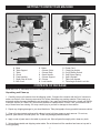
Bench Drill Press
Operator’s Manual
www.rikontools.com
30-120M4
30-120
Record the serial number and date of purchase in your manual for future reference.
Serial Number: _________________________ Date of purchase: _________________________
For technical support or parts questions, email [email protected] or call toll free at (877)884-5167
The serial number can be found on the specication label on the rear of your machine.

2
TABLE OF CONTENTS
SPECIFICATIONS
NOTE: The specications, photographs, drawings and information in this manual represent the current model when the
manual was prepared. Changes and improvements may be made at any time, with no obligation on the part of Rikon
Power Tools, Inc. to modify previously delivered units. Reasonable care has been taken to ensure that the information in
this manual is correct, to provide you with the guidelines for the proper safety, assembly and operation of this machine.
Motor .......................................................................................................... 1/2 HP
Motor Speed (no load).......................................................................... 1,720 RPM
Volts ............................................................................................................. 120 V
Amps, Hertz ....................................................................................... 7.5 A, 60 Hz
Swing ................................................................................................................ 13”
Chuck Size ...................................................................................................... 5/8”
Chuck Taper .................................................................................................... JT3
Drilling Capacity .............................................................................................. 5/8”
Spindle Travel .............................................................................................. 3-1/8”
Spindle Taper .................................................................................................. MT2
Head Rotates ................................................................................................. 360°
Speed Range (RPM) ........................................................................... 220 - 3600
Speeds .............................................................................................................. 16
Quill Diameter ............................................................................... 2-3/16” (55mm)
Table Size ..................................................................................... 11-3/16” Round
Table Tilts ..................................................................................... 90° Left & Right
Table Rotates ................................................................................................. 360°
Maximum Chuck to Table ........................................................................... 16-1/4”
Maximum Chuck to Base ........................................................................... 24-5/8”
Column Diameter ............................................................................ 2-7/8” (74mm)
Height ............................................................................................................... 42”
Base Size .................................................................................... 17-3/4” x 10-1/2”
Net Weight ................................................................................................ 102 lbs.
Specications.....................................................................................................................2
Safety Instructions ........................................................................................................3 - 6
Getting To Know Your Machine ..............................................................................................7
Contents of Package .....................................................................................................7 - 8
Installation ......................................................................................................................8
Assembly .................................................................................................................... 9 - 12
Adjustments...............................................................................................................13 - 14
Maintenance ....................................................................................................................15
Electricals & Wiring Diagram .......................................................................................5 & 15
Troubleshooting .........................................................................................................16
Accessories ..........................................................................................................17
Warranty ..........................................................................................................................17
Parts Diagram .................................................................................................................18
Parts List ................................................................................................................19

3
SAFETY SYMBOLS
IMPORTANT! Safety is the single most important consideration in the operation of this equipment. The following
instructions must be followed at all times. Failure to follow all instructions listed below may result in electric shock,
re, and/or serious personal injury.
There are certain applications for which this tool was designed. We strongly recommend that this tool not be modied
and/or used for any other application other than that for which it was designed. If you have any questions about its
application, do not use the tool until you have contacted us and we have advised you.
SAFETY INSTRUCTIONS
GENERAL SAFETY
KNOW YOUR POWER TOOL. Read the owner’s manual
carefully. Learn the tool’s applications, work capabilities,
and its specic potential hazards.
BEFORE USING YOUR MACHINE
To avoid serious injury and damage to the tool, read and
follow all of the Safety and Operating Instructions before
operating the machine.
1. Some dust created by using power tools contains
chemicals known to the State of California to cause cancer,
birth defects, or other reproductive harm.
Some examples of these chemicals are:
• Lead from lead-based paints.
• Crystalline silica from bricks, cement, and other
• masonry products.
• Arsenic and chromium from chemically treated lumber.
Your risk from these exposures varies, depending on how
often you do this type of work. To reduce your exposure to
these chemicals: work in a well ventilated area and work
with approved safety equipment, such as those dust masks
that are specially designed to lter out microscopic
particles.
2. READ the entire Owner’s Manual. LEARN how to use
the tool for its intended applications.
3. GROUND ALL TOOLS. If the tool is supplied with a 3
prong plug, it must be plugged into a 3-contact electrical
receptacle. The 3rd prong is used to ground the tool and
provide protection against accidental electric shock. DO
NOT remove the 3rd prong. See Grounding Instructions
on the following pages.
4. AVOID A DANGEROUS WORKING ENVIRONMENT.
DO NOT use electrical tools in a damp environment or
expose them to rain.
5. DO NOT use electrical tools in the presence of
ammable liquids or gases.
6. ALWAYS keep the work area clean, well lit, and
organized. DO NOT work in an environment with oor
surfaces that are slippery from debris, grease, and wax.
7. KEEP VISITORS AND CHILDREN AWAY. DO NOT
permit people to be in the immediate work area,
especially when the electrical tool is operating.
8. DO NOT FORCE THE TOOL to perform an operation
for which it was not designed. It will do a safer and
higher quality job by only performing operations for
which the tool was intended.
9. WEAR PROPER CLOTHING. DO NOT wear loose
clothing, gloves, neckties, or jewelry. These items can
get caught in the machine during operations and pull the
operator into the moving parts. The user must wear a
protective cover on their hair, if the hair is long, to
prevent it from contacting any moving parts.
10. CHILDPROOF THE WORKSHOP AREA by
removing switch keys, unplugging tools from the
electrical receptacles, and using padlocks.
11. ALWAYS UNPLUG THE TOOL FROM THE
ELECTRICAL RECEPTACLE when making adjust-
ments, changing parts or performing any maintenance.
SAFETY ALERT SYMBOL: Indicates DANGER, WARNING, or CAUTION. This symbol may be used
in conjunction with other symbols or pictographs.
Indicates an imminently hazardous situation, which, if not avoided, could result in death or
serious injury.
Indicates a potentially hazardous situation, which, if not avoided, could result in death or serious
injury.
Indicates a potentially hazardous situation, which, if not avoided, could result in minor or
moderate injury.
NOTICE: Shown without Safety Alert Symbol indicates a situation that may result in property damage.

4
SAFETY INSTRUCTIONS
16. NEVER LEAVE A RUNNING TOOL UNATTENDED.
Turn the power switch to the “OFF” position. DO NOT
leave the tool until it has come to a complete stop.
17. DO NOT STAND ON A TOOL. Serious injury could
result if the tool tips over, or you accidentally contact the
tool.
18. DO NOT store anything above or near the tool where
anyone might try to stand on the tool to reach it.
19. MAINTAIN YOUR BALANCE. DO NOT extend
yourself over the tool. Wear oil resistant rubber soled
shoes. Keep oor clear of debris, grease, and wax.
20. MAINTAIN TOOLS WITH CARE. Always keep tools
clean and in good working order. Keep all blades and tool
bits sharp, dress grinding wheels and change other
abrasive accessories when worn.
21. EACH AND EVERY TIME, CHECK FOR DAMAGED
PARTS PRIOR TO USING THE TOOL. Carefully check
all guards to see that they operate properly, are not dam-
aged, and perform their intended functions. Check for
alignment, binding or breaking of moving parts. A guard
or other part that is damaged should be immediately
repaired or replaced.
22. DO NOT OPERATE TOOL WHILE TIRED, OR
UNDER THE INFLUENCE OF DRUGS, MEDICATION
OR ALCOHOL.
23. SECURE ALL WORK. Use clamps or jigs to secure
the work piece. This is safer than attempting to hold the
work piece with your hands.
24. STAY ALERT, WATCH WHAT YOU ARE DOING,
AND USE COMMON SENSE WHEN OPERATING A
POWER TOOL.
A moment of inattention while operating power tools may
result in serious personal injury.
26. USE A PROPER EXTENSION CORD IN GOOD
CONDITION. When using an extension cord, be sure to
use one heavy enough to carry the current your product
will draw. The table on the following page shows the cor-
rect size to use depending on cord length and nameplate
amperage rating. If in doubt, use the next heavier gauge.
The smaller the gauge number, the larger diameter of the
extension cord. If in doubt of the proper size of an exten-
sion cord, use a shorter and thicker cord. An undersized
cord will cause a drop in line voltage resulting in a loss of
power and overheating.
USE ONLY A 3-WIRE EXTENSION CORD THAT HAS
A 3-PRONG GROUNDING PLUG AND A 3-POLE
RECEPTACLE THAT ACCEPTS THE TOOL’S PLUG.
27. ADDITIONAL INFORMATION regarding the safe and
proper operation of this product is available from:
• Power Tool Institute
1300 Summer Avenue
Cleveland, OH 44115-2851
www.powertoolinstitute.org
• National Safety Council
1121 Spring Lake Drive
Itasca, IL 60143-3201
www.nsc.org
• American National Standards Institute
25 West 43rd Street, 4th Floor
New York, NY 10036
www.ansi.org
• ANSI 01.1 Safety Requirements for
Woodworking Machines and the
U.S. Department of Labor regulations
www.osha.gov
28. SAVE THESE INSTRUCTIONS. Refer to them
frequently and use them to instruct others.
25. ALWAYS WEAR A DUST MASK TO PREVENT
INHALING DANGEROUS DUST OR AIRBORNE
PARTICLES, including wood dust, crystalline silica dust
and asbestos dust. Direct particles away from face and
body. Always operate tool in well ventilated area and
provide for proper dust removal. Use dust collection
system wherever possible. Exposure to the dust may
cause serious and permanent respiratory or other injury,
including silicosis (a serious lung disease), cancer, and
death. Avoid breathing the dust, and avoid prolonged
contact with dust. Allowing dust to get into your mouth
or eyes, or lay on your skin may promote absorption of
harmful material. Always use properly tting NIOSH/OSHA
approved respiratory protection appropriate for the dust
exposure, and wash exposed areas with soap and water.
12. KEEP PROTECTIVE GUARDS IN PLACE AND IN
WORKING ORDER.
13. AVOID ACCIDENTAL STARTING. Make sure that
the power switch is in the “OFF” position before plugging
in the power cord to the electrical receptacle.
14. REMOVE ALL MAINTENANCE TOOLS from the
immediate area prior to turning “ON” the machine.
15. USE ONLY RECOMMENDED ACCESSORIES. Use
of incorrect or improper accessories could cause serious
injury to the operator and cause damage to the tool. If in
doubt, check the instruction manual that comes with that
particular accessory.

5
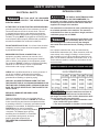
COVER
RAILS
SAFETY INSTRUCTIONS
THE USE OF AN EXTENSION CORD
WITH THIS MACHINE IS NOT RECOMMENDED. For
best power and safety, plug the machine directly into a
dedicated, grounded electrical outlet that is within the
supplied cord length of the machine.
If an extension cord needs to be used, it should only be
for a limited operation of the machine. The extension
cord should be as short as possible in length, and have
a minimum gauge size of 14AWG.
Check extension cords before each
use. If damaged replace immediately. Never use a tool
with a damaged cord, since touching the damaged
area could cause electrical shock, resulting in serious
injury.
Use a proper extension cord. Only use cords listed by
Underwriters Laboratories (UL). Other extension cords can
cause a drop in line voltage, resulting in a loss of power
and overheating of tool. When operating a power tool out-
doors, use an outdoor extension cord marked “W-A” or “W”.
These cords are rated for outdoor use and reduce the risk
of electric shock.
DO NOT MODIFY ANY PLUG. If it will not t the electrical
receptacle, have the proper electrical receptacle installed
by a qualied electrician.
IMPROPER ELECTRICAL CONNECTION of the
equipment grounding conductor can result in risk of
electric shock. The conductor with the green insulation
(with or without yellow stripes) is the equipment ground-
ing conductor. DO NOT connect the equipment grounding
conductor to a live terminal if repair or replacement
of the electric cord or plug is necessary.
CHECK with a qualied electrician or service personnel if
you do not completely understand the grounding
instructions, or if you are not sure the tool is properly
grounded when installing or replacing a plug.
USE ONLY A 3-WIRE EXTENSION CORD THAT HAS
THE PROPER TYPE OF A 3-PRONG GROUNDING PLUG
THAT MATCHES THE MACHINE’S 3-PRONG PLUG AND
ALSO THE 3-POLE RECEPTACLE THAT ACCEPTS THE
TOOL’S PLUG. *
REPLACE A DAMAGED OR WORN CORD
IMMEDIATELY.
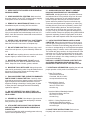
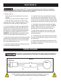
This tool is intended for use on a circuit that has an
electrical receptacle as shown in FIGURE A. It shows a
3-wire electrical plug and electrical receptacle that has
a grounding conductor. If a properly grounded electrical
receptacle is not available, an adapter as shown in
FIGURE B can be used to temporarily
connect this plug to a 2-contact ungrounded
receptacle. The adapter has a rigid lug
extending from it that MUST be connected
to a permanent earth ground, such as a
properly grounded receptacle box.
THIS ADAPTER IS PROHIBITED IN
CANADA.
IN THE EVENT OF A MALFUNCTION OR BREAKDOWN,
grounding provides the path of least resistance for electric
current and reduces the risk of electric shock. This tool
is equipped with an electric cord that has an equipment
grounding conductor and requires a grounding plug (not
included). The plug MUST be plugged into a matching elec-
trical receptacle that is properly installed and grounded in
accordance with ALL local codes and ordinances.
THIS TOOL MUST BE GROUNDED
WHILE IN USE TO PROTECT THE OPERATOR FROM
ELECTRIC SHOCK.
EXTENSION CORDS
Keep the extension cord clear of
the working area. Position the cord so that it will not
get caught on lumber, tools or other obstructions while
you are working with your power tool.
* Canadian electrical codes require extension cords
to be certied SJT type or better.
** The use of an adapter in Canada is not acceptable.
FIG. B
FIG. A
ELECTRICAL SAFETY

SAVE THESE INSTRUCTIONS. Refer to them often.
6
This owner’s manual is not a teaching aid. Use of this owner’s manual is intended to
show assembly, adjustments, and general use.
SPECIFIC SAFETY INSTRUCTIONS FOR DRILL PRESSES
SAFETY INSTRUCTIONS
This machine is intended for the drilling of wood, composite materials, plastics, ferrous and non-ferrus metals.
The permissible workpiece dimensions must be observed (see Technical Specification). Any other use not
as specified, including modification of the machine or use of parts not tested and approved by the equipment
manufacturer, can cause unforeseen damage and invalidate the warranty.
ATTENTION:
Use of this drill press still presents risks that cannot be eliminated by the manufacturer.
Therefore, the user must be aware that wood working machines are dangerous if not used with care and all
safety precautions are adhered to.
1. Do not operate the Drill Press until it is assembled
and you have read all of the instructions.
2. Do not operate the Drill Press unless you are familiar
with its safe operation. If you are not familiar with
the operation of a Drill Press seek advice from your
supervisor, instructor or other qualied individual.
3. If you are using a bench top Drill Press, it must be
securely fastened to a stand or bench.
4. If you are operating a oor Drill Press it must be
securely fastened to the oor.
5. Always clear the table and work area before turning
on the Drill Press.
6. Always use drill bits, cutting tools and accessories
with a 1/2” shank or less.
7. Never place hands near the drill bit, cutting tool or
accessory while operating the Drill Press.
8. Always wear approved, safety eye wear and hearing
protection while operating the Drill Press.
9. Never wear loose clothing, gloves or ties while
operating the Drill Press. Tie loose hair back.
10. Always wear a dust mask and use adequate dust
collection and proper ventilation.
11. Always have a rm footing while operating the
Drill Press.
12. Always keep the work surface and work areas clear
of debris.
13. Never attempt to do set-up work, assembly or layout
work on the Drill Press while it is in operation.
14. Always lock all table, column and head locks before
turning on the Drill Press.
15. Never start the Drill Press with the drill bit, cutting
tool or accessory in contact with the work piece.
16. Never operate the Drill Press with a damaged drill
bit, cutting tool or accessory.
17. Always check that the drill bit, cutting tool or
accessory is held tight in the chuck.
18. Never operate the Drill Press with the chuck key in
the chuck.
19. Always adjust the depth stop to avoid drilling into
the table surface.
20. Never drill material unless it is properly supported.
Non at work pieces require additional support.
21. Always clamp the work piece to the table.
22. Always support large work pieces at the same height
as the table.
23. Never remove the work piece or clear the table until
the Drill Press comes to a complete stop.
24. Never operate the Drill Press with missing, damaged,
worn, loose or defective parts.
25. Never adjust, change speeds or perform main-
tenance on the Drill Press while it is operating.
26. Always clean the work surface and work area when
nished operating the Drill Press.
27. Always disconnect the power when adjusting or
performing maintenance on the Drill Press.
28. Always disconnect the power when nished using
the Drill Press to prevent accidental operation.
WARNING: Drilling, sawing, sanding or machining wood products can expose you to wood dust,
a substance known to the State of California to cause cancer. Avoid inhaling wood dust or use a dust
mask or other safeguards for personal protection.
For more information go to www.P65Warnings.ca.gov/wood.
California Proposition 65 Warning

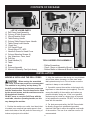
GETTING TO KNOW YOUR MACHINE
CONTENTS OF PACKAGE
7
Model #30-120 13” Benchtop Drill Press is shipped complete in one box.
Unpacking and Clean-up
1. Carefully remove all contents from the shipping carton. Compare the contents with the list of contents to
make sure that all of the items are accounted for, before discarding any packing material. Place parts on a
protected surface for easy identication and assembly. If any parts are missing or broken, please call RIKON
Customer Service (877-884-5167) as soon as possible for replacements. DO NOT turn your machine ON if
any of these items are missing. You may cause injury to yourself or damage to the machine.
2. Report any shipping damage to your local distributor. Take photographs for any possible insurance claims.
3. Clean all rust protected surfaces with ordinary house hold type grease or spot remover. Do not use;
gasoline, paint thinner, mineral spirits, etc. These may damage painted surfaces.
4. Apply a coat of paste wax to the table to prevent rust. Wipe all parts thoroughly with a clean dry cloth.
5. Set packing material and shipping carton aside. Do not discard until the machine has been set up and is
running properly.
B
A
F
D
C
E
O
K
M
N
L
J
H
G
I S
P
T
R
Q
U
A Base
B Table Support
C Table
D Chuck
E Feed Handles
F Depth Stop & Scale
G Belt Cover
H Motor
I Column Collar
J Column Rack
K Crank Handle
L Column Support
M Column
N Lock Handle
O Power Cord
P Chuck Key Holder
Q On/O Safety Switch
R Quill Return Spring
S Quill & Spindle
T Table Lock Handle
U Table Angle Scale & Lock Nut

CONTENTS OF PACKAGE
LIST OF LOOSE PARTS
A Drill Press Head Assembly
B Column & Table Support Arm
C Worm Elevation Gear
D Table Raising Handle
E Column Table Support Lever Handle
F Table Clamp Lever Handle
G Chuck Key
H 5/8” Keyed Chuck
I Chuck Arbor JT3 - MT2
J Handle & Screw for Head Cover
K Column Mounting Screws (4)
L Hex Wrenches - 3mm, 4mm
M Drift Key
N Feed Handles (3)
O Table
P Base
Q Column Assembly
R Manual & Warranty Card (not shown)
8
TOOLS NEEDED FOR ASSEMBLY
- Phillips Screwdriver
- 10mm, 16mm or Adjustable Wrench
- Rubber Mallet or Hammer & Block of Wood
INSTALLATION
MOVING & INSTALLING THE DRILL PRESS
When moving the assembled
Drill Press, at least two people are recommended.
The machine is very heavy, and top heavy. Tilt
the drill press backwards so that one person can
hold the head section. Then the base can be lifted
by the second person, and the machine moved to
the desired new location.
DO NOT move or carry the Drill Press with the
work table, chuck or operating handles, as this
may damage the machine.
1. Position the machine on a solid, level bench that
is located in an area that has ample space in front
and to both sides of the drill press for the moving of
lumber and projects to be drilled.
2. Align the machine so that during use, any kickback
will not face aisles, doorways, or other work areas
that bystanders may be in. Do not locate or use the
machine in damp or wet conditions.
3. If possible, secure the machine to the bench with
lag screws or other fasteners (not supplied). This will
ensure the stability of the machine and reduce any
possible vibration during use. If this is not possible,
the base can be bolted to a larger piece of plywood
to help stabilize the machine. DO NOT use a mobile
base with this machine.
4. For best power and safety, the Drill Press should
be directly plugged into a dedicated grounded
electrical outlet that is within the supplied cord length
of the machine. The use of an extension cord is not
recommended.
A
B
C
D
E
F
J
G
H I
L
M
O
K
N
P Q

ASSEMBLY
THE MACHINE MUST NOT BE
PLUGGED IN AND THE POWER SWITCH MUST BE IN
THE OFF POSITION UNTIL ASSEMBLY IS COMPLETE.
9
Figure 3
Figure 4
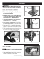
BASE AND COLUMN ASSEMBLY
1. Place the base (A-Fig. 1) on a level oor where
the machine will be used.
2. Attach the column (B-Fig.1) to the base (A-Fig.
1) using four M8x20 hex bolts. Tighten all four
bolts with a 16mm or adjustable wrench.
3. Using an allen wrench (C-Fig. 2) remove the
column collar (D-Fig. 2) as shown.
4. Insert the worm elevation gear (E-Fig. 3) into
the table support bracket (F-Fig. 3) as shown.
5. Place rack (G-Fig. 4) inside the table support
bracket (F-Fig. 4) lining up the teeth as shown.
6. Slide the table support and rack assembly over
the column and replace the column collar.
C
D
Figure 1
Figure 2
B
A
HEAD ASSEMBLY
1. Place the drill press head (A-Fig. 5) onto the
column (B-Fig. 5) as far as it will go.
Assistance is needed for this next step.
B
A
Figure 5
NOTE:
CONTINUED ON NEXT PAGE

ASSEMBLY
10
Figure 7
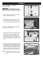
HEAD ASSEMBLY
- CONTINUED
Figure 6
Figure 8
Figure 9
A
B
2. Align the drill press head (A-Fig. 6) with the
base of the drill press (B-Fig. 6).
3. Tighten the drill press head (A-Fig. 7) to the
column (B-Fig. 7) by tightening the two set
screws on the right side of the head as shown.
4. Attach the 3 feed handles into the threaded
holes in the handle hub. Fig. 8
6. Install the idler pulley and drive belts. Simply
slide the pivot post of the idler pulley into the
corresponding hole in the drill press head as
shown. The small drive belt (M24) is mounted
to the
spindle
pulley and the large drive belt
(M25) is mounted to the
motor
pulley. Fig. 9.
NOTE:
Setting the Spindle Speed and Tension
of the drive belts is covered on pages 13
and 14.
THE MACHINE MUST NOT BE
PLUGGED IN AND THE POWER SWITCH MUST BE IN
THE OFF POSITION UNTIL ASSEMBLY IS COMPLETE.
5. Install the small, belt cover Handle Knob onto
the right side of the top lid (A-Fig. 9). Open
the belt cover and insert the Phillips head
screw through the hole in the lid from the
inside. Thread the handle on the outside of the
belt cover and tighten it in place with a screw-
driver.
A
A
B
A
B

ASSEMBLY
11
Figure 10
Figure 11
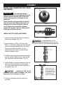
INSTALLING THE CHUCK AND ARBOR
1. Open the chuck jaws as wide as possible to
prevent any damage. (Fig. 10)
2. Insert the arbor (A-Fig. 11) into the chuck
(B-Fig. 11) as shown. Make sure that the arbor
end and receiving tapered hole in the chuck
body rear are clean of grease, oil, rust
protection and any burrs or scratches that
disrupt the taper surface.
3. Carefully insert the chuck and arbor assembly
into the spindle, making sure to align the at
part of the arbor with the spindle. (Fig. 12)
4. Using a mallet or wood and hammer, drive the
chuck and arbor assembly into the spindle.
This will properly seat the chuck assembly on
the spindle. (Fig. 13)
NEVER HIT THE CHUCK
ASSEMBLY WITH A METAL HAMMER. This could
damage the chuck assembly or spindle.
5. Close the chuck jaws with the chuck key
provided.
Figure 12
IMPORTANT!
Figure 13
MAKE SURE THE
JAWS ARE INSIDE
OF CHUCK BODY
TO PROTECT THEM
FROM BEING HIT
DURING ASSEMBLY
OPEN CHUCK JAWS
It is important that the
tapered hole in the chuck, tapered hole in the
spindle and both tapered ends of the arbor
are free of any grease, oil, lacquer or rust
protection.
These tapered surfaces must be absolutely
clean for a precision tting of the parts, so
slipping of the chuck during use does not
occur unless there is extreme rotational
pressure during use. This is a safety feature
of this type of friction t joint.
INSTALLING & REMOVING THE CHUCK
AND ARBOR
THE MACHINE MUST NOT BE
PLUGGED IN AND THE POWER SWITCH MUST BE IN THE
OFF POSITION UNTIL ALL ADJUSTMENTS ARE COMPLETE.

ASSEMBLY
12
A
C
B
B
A
Figure 16
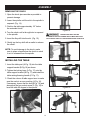
3. Check the column & table support arm to make
sure the scale is on zero position (A-Fig. 16).
If necessary, loosen the hex bolt (B-Fig. 16) and
also adjust the hex socket screw (C-Fig. 16) to
level the table 90 degree to the spindle.
Figure 17
REMOVING THE CHUCK
1. Open the chuck jaws as wide as possible to
prevent damage.
2. Lower the spindle until the slot in the spindle is
exposed. (Fig. 14)
3. Position the table approximately 1/2” below
the extended chuck.
4. Turn the chuck until a through hole is exposed
in the spindle.
5. Insert the Key-drift into the slot. (Fig. 15).
6. Gently tap the key-drift with a mallet to release
the chuck.
NOTE: To avoid damage to the chuck, make
sure to place a hand below the chuck to catch
it as it is released from the spindle.
Figure 15
Figure 14
1. Insert the table post (A-Fig. 16) into the table
support bracket (B-Fig.16) as shown.
2. Tighten the locking lever (A-Fig. 17) onto the
table support bracket (B-Fig. 17) and install the
table raising/lowering handle (C-Fig. 17).
B
A
C
Figure 18
THE MACHINE MUST NOT BE
PLUGGED IN AND THE POWER SWITCH MUST BE IN THE
OFF POSITION UNTIL ALL ADJUSTMENTS ARE COMPLETE.
INSTALLING THE TABLE

13
B
A
Figure 19
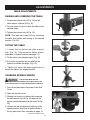
TABLE ADJUSTMENTS
RAISING AND LOWERING THE TABLE
1. Loosen the column lock (A-Fig. 19) on the
table support bracket (B-Fig. 19).
2. Turn the crank to raise or lower the table to the
desired height.
3. Tighten the column lock (A-Fig. 19).
NOTE:
The table can rotate 360
o
by loosening
the table lock handle and turning to the desired
position. (Fig. 20)
TILTING THE TABLE
1. Loosen the nut below the table support
arm. (Fig. 18). This requires a 24mm socket,
adjustable, or special wrench (see page 17).
2. Tilt the table to the desired angle. (Fig. 21).
3. A tilt scale and pointer are provided on the
bracket to indicate the angle. (Fig. 18).
4. Tighten nut below the table support arm to
secure the table in the angled position.
CHANGING SPINDLE SPEEDS
Figure 20
Figure 21
Figure 22
A
1. Turn o and disconnect the power to the Drill
Press.
2. Open the top belt cover.
3. Release the tension on the belt by loosening
the belt tension lock (A-Fig. 22) and pull the
tension handle backward on the motor (B-Fig.
22).
4. Choose the desired speed by referring to the
speed selection chart that is applied inside of
the top belt cover. Also, see chart on page 14.
ADJUSTMENTS
THE MACHINE MUST NOT BE
PLUGGED IN AND THE POWER SWITCH MUST BE IN THE
OFF POSITION UNTIL ALL ADJUSTMENTS ARE COMPLETE.
CONTINUED ON NEXT PAGE
B

ADJUSTMENTS
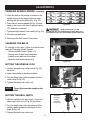
SETTING THE SPINDLE LOCK
1. Loosen the depth stop collar lock (A-Fig. 25)
as shown.
2. Lower the spindle to the desired depth.
3. Turn the depth stop collar clockwise until the
collar stops (B-Fig. 25).
4. Tighten the depth stop collar lock.
Figure 25
Figure 23
Figure 26
CHANGING SPINDLE SPEEDS
- continued
Figure 24
NOTE:
SETTING THE DRILL DEPTH
1. With the spindle in the up position, loosen the
depth stop collar lock (A-Fig. 25) as shown.
2. Turn the depth stop collar clockwise until the
pointer reads the desired drill depth on the
scale (B-Fig. 25).
3. Tighten the depth stop collar lock.
5. Place the belt on the pulleys in relation to the
speed chosen on the speed selection chart
starting with the motor pulley rst. (Fig. 23)
6. Push the belt tension handle (B-Fig. 24) back
ward on the motor until there is approximately
1/2" deection in the belt.
7. Tighten the belt tension lock handle (A-Fig. 24).
8. Close the top belt cover.
9. Reconnect the Drill Press to the power.
Figure 26 shows the spindle in the
locked position.
14
THE MACHINE MUST NOT BE
PLUGGED IN AND THE POWER SWITCH MUST BE IN THE
OFF POSITION UNTIL ALL ADJUSTMENTS ARE COMPLETE.
A
CHANGING THE BELTS
To change a worn belt, follow the same basic
steps for Changing Spindle Speeds:
- Release the belt tension (steps 1-3)
- Remove the old belt from the pulleys
- Install the new belt onto the pulleys
- Reset the belt tension (steps 5-9)
A
B
SPINDLE
SHOWN
IN THE
LOCKED
POSITION
B

15
MAINTENANCE
Turn the power switch “OFF” and disconnect the plug from the outlet prior to adjusting
or maintaining the machine. DO NOT attempt to repair or maintain the electrical components of the motor.
Contact a qualied service technician for this type of maintenance.
1. Before each use:
- Check the power cord and plug for any wear or
damage.
- Check for any loose screws, hardware or parts.
- Check the area to make sure it is clear of any
misplaced tools, lumber, cleaning supplies, etc. that
could hamper the safe operation of the machine.
2. To avoid a build-up of wood dust, regularly clean
all parts of the machine using a soft cloth, brush or
compressed air. A general cleaning should be done
after every use to avoid future problems and ensure
the machine is in ready condition for its next use.
WARNING: If blowing sawdust, wear proper eye pro-
tection to prevent debris from blowing into eyes.
3. Keep the machined surfaces of the drill press table
and base free of resin and rust. Clean them regularly
with a non-flammable solvent, then coat with a light
film of dry lubricant spray or wax.
4. Lubricate the table bracket and locking lever bolts
to keep them operating smoothly.
5. Clean the column on a regular basis to prevent
the build-up of dust, drilling residue and rust. Treat
the posts with a dry lubricant spray or a light coating
of wax. Do not use ordinary oil which will collect dust
and hamper the movement of parts along the column.
6. Periodically, lower the quill assembly and apply
a light coating of machine oil to the quill and spindle
surfaces. Raise and lower the quill a few times to
distribute the oil on all of the internal surfaces.
7. Apply #2 tube grease to the worm gears in the
table elevation mechanism and rack to keep them
operating smoothly.
8. The ball bearings in the spindle and pulley assem-
blies are lifetime lubricated, sealed, and do not need
any further care.
9. Keep the drive belt and pulley surfaces free of oil
and grease. Periodically, check the drive belt for wear
and replace if necessary.
This machine must be grounded. Replacement of the power supply cable should only
be done by a qualied electrician. See page 5 for additional electrical information.
WIRING DIAGRAM
Motor
Switch
120V Plug
DO NOT attempt to repair or maintain the electrical components of the motor.
Contact a qualied service technician for this type of maintenance.

16
TROUBLESHOOTING
TROUBLE PROBABLE CAUSE REMEDY
Noisy Operation 1. Incorrect belt tension. 1. Adjust tension.
2. Dry Spindle. 2. Lubricate spindle.
3. Loose spindle pulley. 3. Checking tightness of retaining nut
on pulley and tighten if necessary.
4. Loose motor pulley. 4. Tighten set screws in pulleys.
Drill Bit Burns 1. Incorrect speed. 1. Change speed.
Material 2. Chips not coming out of hole. 2. Retract drill bit frequently to clear chips.
3. Dull drill bit. 3. Resharpen drill bit.
4. Feeding too slow. 4. Increase the speed.
5. Not Lubricated 5. Lubricate drill bit.
Drill bit leads off, 1. Hard grain in wood or lengths 1. Resharpen drill bit correctly.
hole not round. of cutting lips and/ or angles
not equal.
2. Bent drill bit. 2. Replace drill bit.
Wood splinters 1. No "back up material" 1. Use "back-up material"
on underside of under workpiece.
workpiece.
Wood piece pulled 1. Not supported or 1. Support workpiece or clamp it.
loose from hands. clamped properly.
Drill bit binds 1. Workpiece pinching drill bit 1. Support workpiece or clamp it.
in workpiece. or excessive feed pressure.
2. Improper belt tension. 2. Adjust belt tension.
Excessive drill bit 1. Bent drill bit. 1. Use a straight drill bit.
runout or wobble. 2. Worn spindle bearings. 2. Replace bearings.
3. Drill bit not properly 3. Install drill bit properly.
installed in chuck.
4. Chuck not properly installed. 4. Install chuck properly.
Quill Returns too 1. Spring has improper tension. 1. Adjust spring tension.
slow or too fast.
Chuck will not stay 1. Dirty, grease, or oil on the 1. Using a household detergent, clean the
attached to spindle, tapered inside surface of tapered surface of the chuck and spindle
it falls off when trying chuck or on the spindle's to remove all dirt, grease and oil.
to install it. tapered surface.

17
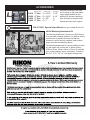
ACCESSORIES
Approx. Sizes JAWS L x W Jaws Open
93-010 3” Vise 3” x 13/16” 3-1/4”
93-020 4” Vise 4” x 15/16” 4-1/4”
93-030 5” Vise 5” x 7/8” 5”
93-040 6” Vise 6” x 1” 6”
29-202 Mortising Attachment Kit
The Mortising Attachment converts your Drill Press in
to an accurate mortising machine. It is ideal for drilling
square holes for mortise & tenon joints that are
commonly used in furniture, cabinets, sash, pattern
shops and other woodworking plants.
The Mortising Attachment Kit can be installed on most
any drill press with a collar size of: 40mm, 48mm,
50.8mm, 55mm, 60mm, 66mm or 75mm. Kit includes
yoke, collar adapters, fence, hold downs, 4 chisels &
bits (1/4”, 5/16”, 3/8” 1/2”) and plastic storage case.
All metal construction with slots
for mounting on drill press tables.
Large toggle handles for fast
adjusting of the jaws. Machined
base and jaws to maintain table
atness and solid work support.
P30-217-22D Special 24mm Wrench for use on table tilt hex bolt.
®
RIKON Power Tools Inc. (“Seller”) warrants to only the original retail consumer/purchaser of our products that each product
be free from defects in materials and workmanship for a period of five (5) years from the date the product was purchased
at retail. This warranty may not be transferred.
This warranty does not apply to defects due directly or indirectly to misuse, abuse, negligence, accidents, repairs,
alterations, lack of maintenance or normal wear and tear. Under no circumstances will Seller be liable for incidental or
consequential damages resulting from defective products. All other warranties, expressed or implied, whether of
merchantabilit
merchantability, fitness for purpose, or otherwise are expressly disclaimed by Seller. This five-year warranty does not cover
products used for commercial, industrial or educational purposes. The warranty term for these claims will be limited to a
two-year period.
This limited warranty does not apply to accessory items such as blades, drill bits, sanding discs, grinding wheels, belts,
guide bearings and other related items.
Seller shall in no event be liable for death, injuries to persons or property, or for incidental, contingent, special, or
consequential damages arising from the use of our products.
T
To take advantage of this warranty, proof of purchase documentation must be provided which has the date of purchase and
an explanation of the complaint.
The Seller reserves the right to effect at any time, without prior notice, those alterations to parts, fittings, and accessory
equipment which they may deem necessary for any reason whatsoever.
To register your machine online, visit RIKON at www.rikontools.com/warranty
To take advantage of this warranty, or if you have any questions,
please contact us at 877-884-6167 or email [email protected]

18
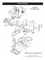
PARTS DIAGRAM
16
Parts Explosion
NOTE: Please reference the Manufacturer’s Part
Number when calling for Replacement Parts.
For Parts under Warranty,
the Serial Number of your machine is required.
30-120
13” Drill Press
1
1
1

19
PARTS LIST
NOTE: Please reference the Manufacturer’s Part Number when calling for Replacement Parts.
For Parts under Warranty, the Serial Number of your machine is required.
1A
2A
3A
4A
6A
7A
8A
9A
10A
11A
12A
13A
14A
15A
16A
17A
18A
19A
3B
4B
5B
6B
7B
8B
9B
10B
11B
12B
1C
2C
3C
4C
5C
6C
7C
8C
9C
10C
11C
12C
13C
P30-120-1A
P30-120-2A
P30-120-3A
P30-120-4A
P30-120-6A
P30-120-7A
P30-120-8A
P30-120-9A
P30-120-10A
P30-120-11A
P30-120-12A
P30-120-13A
P30-120-14A
P30-120-15A
P30-120-16A
P30-120-17A
P30-120-18A
P30-120-19A
P30-120-3B
P30-120-4B
P30-120-5B
P30-120-6B
P30-120-7B
P30-120-8B
P30-120-9B
P30-120-10B
P30-120-11B
P30-120-12B
P30-120-1C
P30-120-2C
P30-120-3C
P30-120-4C
P30-120-5C
P30-120-6C
P30-120-7C
P30-120-8C
P30-120-9C
P30-120-10C
P30-120-11C
P30-120-12C
P30-120-13C
Screw-Hex Soc Set M6
Collar-Rack
Gear-Helical
Crank
Table
Clamp-Table
Screw-Hex Head M16x20-35
Arm-Table w/Scale
Base
Support Column
Screw-Hex HD M10x1.5-40
Screw-Hex Soc Set M10
Tube Column
Rack
Clamp-Column
Support-Table w/Indicator
Worm-Elevation Gear
Pin-Gear
Ring-Retaining
Bearing-Ball 17mm
Washer-Rubber
Tube-Quill
Key-Chuck
Chuck 5/8”
Arbor JT3 - MT2
Drift Key
Spindle
Bearing-Ball
Ring- Retaining
Bearing-Ball 25mm
Spacer-Bearing
V-Belt M24
Nut-Pulley
Pulley-Spindle
Insert-Pulley
Guard-Pulley w/Labels
Screw-RD HD Washer
Screw-Set M10x1.5-12
Pulley-Motor
Knob
Screw-Pan HD M5x0.8-12
14C
15C
16C
1D
2D
3D
4D
5D
6D
7D1
9D1
10D1
11D
12D
13D
14D
15D
16D
19D
20D
21D
22D
23D
24D
25D
26D
27D
28D
36D
37D
38D
39D
40D
41D
42D
43D
44D
45D
46D
47D
48D
P30-120-14C
P30-120-15C
P30-120-16C
P30-120-1D
P30-120-2D
P30-120-3D
P30-120-4D
P30-120-5D
P30-120-6D
P30-120-7D1
P30-120-9D1
P30-120-10D1
P30-120-11D
P30-120-12D
P30-120-13D
P30-120-14D
P30-120-15D
P30-120-16D
P30-120-19D
P30-120-20D
P30-120-21D
P30-120-22D
P30-120-23D
P30-120-24D
P30-120-25D
P30-120-26D
P30-120-27D
P30-120-28D
P30-120-36D
P30-120-37D
P30-120-38D
P30-120-39D
P30-120-40D
P30-120-41D
P30-120-42D
P30-120-43D
P30-120-44D
P30-120-45D
P30-120-46D
P30-120-47D
P30-120-48D
Pivot-Idler
Pulley-Center
Bearing-Ball 15mm
Knob-Motor Adjusting
Screw-Socket Set M10
Handle-Belt Tension
Pin-Stop
Ring-Depth Stop w/Scale
Lock-Depth Screw
Hub
Knob on Feed Rod
Feed Rod
Lock Washer Ext.M5
Screw-Pan HD M5
Box Switch
Screw-Pan HD M5
Switch-Locking
Screw-Pan HD M4.2
Cover-Switch Plate
Lead Assembly 3
Screw-Set Special 10
Nut-Hex M10x1.5
Seat-Spring
Retainer-Spring
Spring-Torsion
Cap-Spring
Nut-Hex M12x1.5-8
Head w/Pointer and Trim
Clamp-Cord
Support-Motor Bracket
Screw-Hex HD M8
Washer 8x16x1.6
Mount-Motor
Cord-Motor
Nut-Hex M8x1.25
Motor
Nut-Hex M12x1.75
Lock Washer 1/2
Support-Motor Bracket
Screw Hex HD M8
Lever-Adjusting
KEY
NO.
DESCRIPTION PART NO.
KEY
NO.
DESCRIPTION PART NO.

www.rikontools.com
30-120M4
30-120
For more information:
16 Progress Road
Billerica, MA 01821
877-884-5167 / 978-528-5380
-
 1
1
-
 2
2
-
 3
3
-
 4
4
-
 5
5
-
 6
6
-
 7
7
-
 8
8
-
 9
9
-
 10
10
-
 11
11
-
 12
12
-
 13
13
-
 14
14
-
 15
15
-
 16
16
-
 17
17
-
 18
18
-
 19
19
-
 20
20


Rikon Power Tools 30-120 User manual
- Type
- User manual
- This manual is also suitable for
Ask a question and I''ll find the answer in the document
Finding information in a document is now easier with AI
Related papers
-
Rikon Power Tools 30-217 User manual
-
-
-
-
-
-
-
-
-
Other documents
-
Porter-Cable PCXB620DP User manual
-
RIDGID DP15501 User manual
-
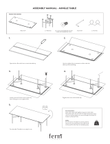 ferm LIVING Mingle Table Assembly Manual
-
King Canada KC-117FC User manual
-
-
-
-
-
-
