
English ASSEMBLY INSTRUCTION
Español INSTRUCCIONES PARA EL ENSAMBLAJE
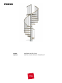
PHOENIX

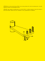
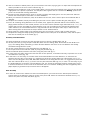
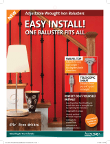
ATTENTION: for the correct xing of B20, turn the key around 90° from the contact point. A further
additional rotation could damage the tread.
ATENCIÓN: para apretar correctamente los tornillos B20 es suciente apretar la llave 90° desde el
punto de contacto. Apretar más de lo indicado es inútil y puede dañar los peldaños.
Page is loading ...

PHOENIX
English
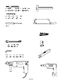
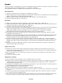
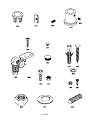
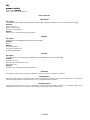
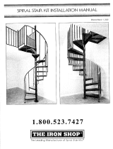
Before starting the assembly process, unpack all components of the staircase. Lay them out on a large surface and
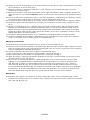
check the quantity of all the pieces, by consulting the table TAB.1 (A = Code, B = Quantity).
Inside the staircase box you will also nd a DVD which we suggest watching before proceeding to assemble.
For customers in the USA there is a customer assistance number 1-888 STAIRKT, which you can telephone in case
of problems.
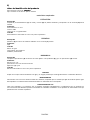
Preliminary Assembly
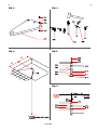
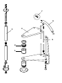
Assemble the parts C24, C25 and B20 to the treads (L03) (g. 2).1.
Carefully measure the oor-to-oor height and determine the required number of spacers (D08) (TAB.2) and 2.
prepare them onto their proper spacer (D15) (TAB2)
Assemble the parts C63, C65, C66 onto the baluster (C03), by using the part B68 (g. 3).3.
Assemble the base G03, B17 and B46 (g. 1).4.
Assembly
Determine and mark on the oor the centre of the opening, then position the base (G03+B17+B46) (g. 4).5.
Drill with drill bit Ø 14 mm (6. 9 / 16") and x the base (G03+B17+B46) into the oor by means of the parts B13 (g. 1).
Screw the pole (G02) into the base (G03+B17+B46) (g. 1).7.
Insert the base plate cover (D12) into the pole (G02) (g. 5).8.
Insert the spacers (D08), then the shorter spacer (D14), the spacers (D08), the rst tread (L03), the spacers 9.
D08), the spacer (D15), the spacers (D08) and another tread (L03) and so on. Add alternatively the treads
alternately one to the right and one to the left, so as to distribute the weight in a balanced way (g. 5).
When you reach the end of the pole (G02), screw the part B47 on it, then add the second pole (G02) and 10.
continue with the stair assembly (g. 5)
When you reach the end of the pole (G02), screw on it the part B46 and the part G01. (Screw the part G01, 11.
until its upper end sticks out approximately 15 cm (6’’) from the stair height (g. 6). Continue adding the treads,
by using the part D01 inserted into the tread (L03).
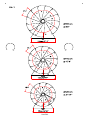
Finally add the stair landing (E02). After having chosen the stair rotation (g. 7), position the landing (E02) with 12.
the small hole (which is needed for the baluster passage (C03)) on the arrival side of the treads (L03) (g. 8)
Cut the landing (E02), if necessary, in relation to the oor opening.
Insert the parts B05, B04 and screw the part B03 sufciently (g. 1) but keeping in mind that the treads still 13.
have to be rotated (g. 1).
Fitting of the Landing
Approach the part F12 to the oor. Determine the position, maintaining a distance of about 15 cm (6”) from the 14.
external side of the landing (E02), pierce with drill bit Ø 14 mm (9 / 16") and x securely by using the part B13 (g. 1).
Fix the parts F12 to the landing (E02), by using the parts C58 (pierce the landing (E02) with the drill bit Ø 5 mm (15. 13 / 64").
Position the parts B95.16.
Assembly of the Railing
Spread-out the treads (L03) fan-like. It is now possible to use the stair.17.
Starting from the landing (E02), insert the longer railing balusters (C03), that build the connection between the 18.
treads (L03). Keep the balusters (C03) with the part C63 and the pierced part to the top (g. 8). Tighten only the
part B20 of the lower tread (g. 2).
Check very carefully the vertical position of the inserted balusters C03. This control is very important for 19.
insuring the best results.
Tighten securely the part B03 (g. 8).20.
Tighten securely the part B02 of the upper tread (g. 2).21.
Check once more the vertical position of the railing balusters (C03) and, if necessary, correct it, by repeating the 22.
previous operations.
Position the rst baluster (C03). Cut one long baluster (C03) to obtain the same size as all others you 23.
assembled previously.
Fix into the oor in relation to the rst baluster (C03), the part F01, by piercing with the drill bit Ø 8 mm (24. 5 / 16").
Use the parts C58, B12, B83 and B02 (g. 1). Then assemble the reinforcing part (F07).
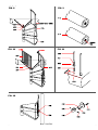
Find the handrail piece not marked in red colour (A13) and the one marked in red colour (A14) which will be 25.
used for the railing of the landing (E02) (g. 9).

PHOENIX
Start to model the handrail pieces (A13) not marked in red colour, trying to give it a shape that corresponds the 26.
nearest possible to the curve of the staircase (g. 1).
Beginning from the baluster (C03) on the landing (E02), start to fasten the handrail (A13), that you have already 27.
slightly bent in the previous operation. Use the parts C64 together with the screw driver. Warning: position the
join line of the handrail covering downwards.
Connect all other handrail pieces (A13), by screwing, glueing and shaping them. Use the parts B33 and D35. 28.
Position the thickest part of item D35 so it faces outwards.
When you reach the rst baluster (C03) at the bottom of the stair, cut the excess piece of the handrail with a 29.
hacksaw.
Complete the handrail (A13) by assembling the part A12. Use the parts C64 and the glue (X01) (g. 1).30.
Insert all remaining railing balusters into the treads (L03), tighten the part B20 and x to the handrail (A13), 31.
paying careful attention to the vertical position. (for the stairs with a diameter larger than 140 cm (4’7 1 / 8”), we
suggest that you rst assemble the shorter balusters) (g. 10). According to the geometrical characteristics
of the staircase, the intermediate balusters may protrude from the lower part of the step, in which case we
advise cutting them off level with the step to obtain a more attractive nish.
Check again the regular shape of the handrail (A13) and, if necessary, correct it with a rubber hammer.32.
Complete the railing assembly by tting the parts B82 into the lower part of the balusters (C03) and the parts 33.
C19 into the lateral part of the treads (g. 1).
Assembly of the Balustrade
Screw the baluster (C04) into the part G01 that sticks out from the landing (E02) (g. 8).34.
Set the parts F01, by using the parts C58, B83, B02 onto the landing (E02). Pierce with the drill bit Ø 5 mm 35.
(13/64") the landing (E02), maintaining a similar distance between the holes as the one between the already
assembled railing balusters (C03).
Set the shorter balusters (C03) and tighten the part B02 (g. 1)36.
Fix the part A15 into the baluster (C04), by using the part B02 (g. 1).37.
Fix the handrail (A14) marked in red colour, using the parts C64 (g. 1).38.
In case there were walls around the stair well and on their position, it could be necessary to position one or two 39.
more balusters (C03) (g. 10).
In that case it is necessary to consider either the distance between all other balusters, or otherwise the 40.
distance from the wall. For the xing it is suggested to pierce the landing (E02) with a drill bit Ø 5 mm (13 / 64")
and to use the xing parts F01, C58, B83, B02. Whereas for the xing into the oor it is suggested to pierce the
oor with a drill bit Ø 12 mm (15 / 32") and to use the parts F01, B02, B87 (g. 11). In case it is necessary to join
the landing baluster to the oor- mounted baluster, (g. 10), shape the handrails carefully, following the curves.
If wrinkles should form on the inside of the handrails, this is not a defect. Rubbing the area energetically with a
paper napkin (to generate heat) will cause them to disappear.
Final Assembly
In order to re-inforce the staircase at the intermediate points, you must x into the wall the parts F09 and 41.
connect them to the balusters (C03) by means of the parts F08. Pierce the wall with a drill bit Ø 8 mm (5 / 16")
and use the parts C50, C49, C58, B12 (g. 12).
Page is loading ...
Page is loading ...

PHOENIX
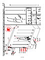
A B
Ø 120 Ø 140 Ø 160
3' 11 1/4" 4' 7 1/8"
5' 3"
A12 3 3 3
A13 5 5 5
A14 1 1 1
A15 2 2 2
B02 13 15 15
B03 1 1 1
B04 1 1 1
B05 1 1 1
B12 7 7 10
B13 6 6 6
B17 1 1 1
B20 40 52 52
B33 6 6 6
B46 2 2 2
B47 1 1 1
B82 24 36 36
B83 9 11 11
B95 3 3 3
C03 33 47 47
C04 1 1 1
C19 40 52 52
C23 2 2 2
C24 72 101 101
C25 40 52 52
C49 2 2 3
C50 2 2 3
C58 21 23 26
C63 33 47 47
C64 73 101 101
C65 33 47 47
C66 33 47 47
D01 4 6 6
D08 119 119 119
D12 1 1 1
D14 1 1 1
D15 12 12 12
E02 1 1 1
F01 9 11 11
F07 1 1 1
F08 2 2 3
F09 2 2 3
F12 3 3 3
G01 1 1 1
G02 2 2 2
G03 1 1 1
L03 12 12 12
X01 1 1 1
TAB 1
Page is loading ...

PHOENIX
English
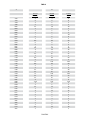
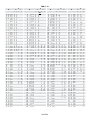
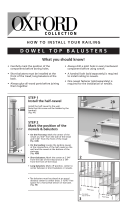
To determine the necessary number of spacers (D08), you must look-up the table TAB.2 (H = Height, A = Rises, X =
quantity of spacers (D08) to position onto the spacer (D15), Y = quantity of the spacers (D08) to position onto the
spacer (D14).
Example: given a oor-to-oor height of 298 cm (9’ 9 3/8”) and a staircase with 13 treads, you must proceed as
follows;
At height (298 cm (9’ 9 1. 3/8”) in the row H) look-up the number of necessary spacers (X=6, Y=12, in the row
A/13).
Distribute the spacers (D08), as follows: 6 spacers (D08) onto every spacer (D15) positioning three spacers on 2.
the top and three spacers on the bottom, twelve spacers (D08) onto the only spacer (D14), the shortest one,
positioning three on the top and nine on the bottom.
Español
Para determinar la cantidad necesaria de discos distanciadores (D08) utilizar la TABLA 2 (H =altura, A = tabicas,
X = numero de discos distanciadores (D08) a colocar sobre los distanciadores (D15), Y = numero de discos
distanciadores (D08) a colocar sobre el distanciador (D14).
Ejemplo: para una altura de pavimento a pavimento de 298 cm (9’9 3/8”) y una escalera con 13 peldaños es
necesario;
En la línea de la altura (298 cm (9’ 9 1. 3/8”), en la columna H), leer la cantidad de discos distanciadores necesarios
(X = 6, Y = 12, en la columna A/13).
Distribuir los discos distanciadores (D08), de la siguiente manera: 6 discos distanciadores (D08) sobre cada 2.
distanciador (D15) colocando 3 arriba y 3 abajo, 12 discos distanciadores (D08) sobre el único distanciador
(D14), él mas corto, colocar 3 discos arriba y 9 abajo.
Page is loading ...
Page is loading ...
Page is loading ...
Page is loading ...
Page is loading ...
Page is loading ...
Page is loading ...
Page is loading ...

PHOENIX
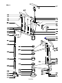
product details
trade name: PHOENIX
type: spiral round plan staircase
used materials
STRUCTURE
description
composed by metal spacers (1) and plastic spacers (2) stacked and packed on the central modular pole (3)
materials
spacers: Fe 370
plastic spacers: ABS
pole: Fe 370 galvanized
finishing
spacers: oven varnishing with epoxy powders
TREADS
description
wooden circular treads (4) stacked on the central pole (3)
materials
beech
finishing
colour: water-base
undercoat: polyurethane
nishing: polyurethane
RAILING
description
composed by metal vertical balusters (5) xed to treads (4) and by a PVC handrail (6)
materials
balusters: Fe 370
handrail: PVC with aluminium core
xings
(7): nylon
finishing
spindles: oven varnishing with epoxy powders
CLEANING
clean with a soft wet cloth, without any product containing solvents or abrasive materials.
MAINTENANCE
about 12 months after the installation date, check the tightening of bolts on the various components. all non-routine
maintenance procedures must be carried out in a strictly professional manner.
USE PRECAUTION
avoid any improper use that is not in accordance with the product. possible violations or installations which don’t
comply with the providers instructions can invalidate the agreed product conformities.
GB)
Page is loading ...

For further information pertaining to these assembly instructions, additional parts or general
questions regarding products or assembly please call, fax or email us at:
ARKE' by Fontanot
Albini & Fontanot SpA
75 Jackson Street, Suite 303
Newnan, GA 30263
Toll Free: (888) 782 - 4758
Phone: (770) 683 - 7200
Fax: (770) 683 - 7209
Email: [email protected]
-
 1
1
-
 2
2
-
 3
3
-
 4
4
-
 5
5
-
 6
6
-
 7
7
-
 8
8
-
 9
9
-
 10
10
-
 11
11
-
 12
12
-
 13
13
-
 14
14
-
 15
15
-
 16
16
-
 17
17
-
 18
18
-
 19
19
-
 20
20
-
 21
21


Ask a question and I''ll find the answer in the document
Finding information in a document is now easier with AI
in other languages
- español: Arke K07144 Guía de instalación
Related papers
-
Arke K03071 Installation guide
-
Arke K07148 Installation guide
-
-
-
-
-
-
-
-
Other documents
-
WM Coffman 802428 Installation guide
-
Everbilt 20334 Operating instructions
-
 Ole Iron Slides SP121-WR038CSB Installation guide
-
 The Iron Shop EB5613 Installation guide
-
Mylen STAIRS EC60P12V012 Installation guide
-
Mylen STAIRS EC60Z14A001 Installation guide
-
Mylen STAIRS EP42B14B101 Installation guide
-
 Colonial Elegance K5015-36-P06 Installation guide
-
-
Mylen STAIRS CS60G09GS11 Installation guide


