Page is loading ...

1 / 6
■
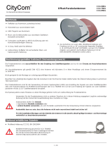
Antenna foot is self-centring, for masts with a diameter 32-50 mm
■
Raised FM antenna, entire mast length can be used
■
Additional antenna cable can be inserted through the antenna
foot into the mast
ARA 10 210115
ARA 20 210116
ARA 30 210117
AM/FM antennas
Features
Proper use (use for the intended purpose)
AM/FM antennas are intended exclusively for the reception of terrestrial radio signals and
only for use as domestic antennas.
DIN 4131 specifi es that a domestic antenna should have no more than 6 m free mast length and
a fi xed-end moment up to 1650 Nm.
It is unsuitable for mounting on structures that are liable to vibration.
Make absolutely sure that the values for the maximum load listed in the Technical Data (on the last
page) are complied with. If this load is exceeded, parts could break away!
Do not use the antenna for purposes other than those listed in this manual! Any
use other than that specifi ed above will invalidate the warranty or guarantee.
In particular, never
• modify any of its components or
• fi t any components other than those expressly intended by the manufacturer for
use with the antenna.
Breach of these rules may lead to the antenna no longer being suffi ciently
stable and safe!
• Under no circumstances install antennas in the vicinity of overhead power cables, otherwise the required clearances,
which are absolutely essential, may no longer be satisfi ed. Maintain a clearance of at least 1 m from all other electrical
equipment in all directions!
If you or metal parts of the antenna touch any electrical device there is a serious risk of a fatal electric shock!
• Never work on antenna systems during a thunderstorm or when a thunderstorm is approaching.
There is a risk of a fatal electric shock!
Basic safety precautions
Before you install, connect or use the antenna, make sure that you comply with the instructions
in this manual!
If you disregard these instructions,
• malfunctions may arise, creating risks to your life and health,
• defects in the installation or the connection may cause damage to the antenna or to the attachment
point,
• the manufacturer will not accept liability for malfunctions and damage arising!
ARA 10
ARA 20
ARA 30

2 / 6
When working on antenna systems, please remember your duty of care towards your fellow human beings!
Keep the manual for any questions that arise later, and if the building passes to another owner, pass it on to the new owner!
Selecting the installation site
It is essential to select the correct installation site. This determines whether your antenna can be erected safely and perform to its
optimum capabilities.
When selecting the installation site, take account of special features of the structure of the building. If the installation is at the edge of
the roof or the building or on a cylindrical structure, DIN 1055, parts 4 and 4131 specifi es the increased wind and vibration loadings
that should be allowed for. The dynamic properties of the antenna and the structure can interact and cause problems.
Disregarding these considerations can lead to the maximum load or vibration fatigue stress listed in the Technical Data being
exceeded.
• Never install antennas on buildings with easily fl ammable roof coverings such as straw, rushes or similar materials!
Otherwise there is a risk of fi re due to atmospheric overvoltages (static charges) or lightning discharges
(e.g. during thunderstorms).
• The installation operations described here assume good craftsmanship capabilities and knowledge of the behaviour
of materials under the effects of wind. Therefore if you do not possess the required skills, have this work performed
by a specialist.
• The person doing the work must wear strong non-slip footwear, must not be liable to dizziness, must be able to move
around safely on the roof and have a secure standing and attachment position (if necessary, wear a safety harness
when on the roof).
• Make sure that the roof is able to bear your weight. Never walk on fragile or unstable surfaces! In case of doubt,
contact a qualifi ed specialist dealer or specialist roofi ng contractor to fi nd an appropriate installation location.
• Do not go on to roofs or other high places without a correctly attached safety harness that is in good condition.
Otherwise use a work platform.
• Ladders or other means of climbing must be in faultless condition (dry, clean and non-slip). Never build any
irresponsible “scrambling towers”!
• If there is a risk that passers-by may be injured by items falling from above during installation, you must close off the
risk area using barriers! Make sure that no-one is underneath the installation location.
Risk of death or injury due to falling from the roof, falling through the roof and falling parts, plus the
possibility of damage to the roof.
• The respective national safety regulations and current standards such as DIN EN 60728-11 should be complied with.
• Any other use or failure to comply with these instructions will invalidate the warranty.

3 / 6
Installing the antenna
When installing the antenna mast, ensure that it is standing
upright.
a) Requirements on the antenna carrier (to DIN EN 60728-11)
Use only masts or support tubes that are designed for
installation of antennas. Other tubes generally do not have
the strength required to withstand the forces of wind and
weather.
• Select a mast or an extending mast with a wall thickness
of at least 2 mm and a diameter of 32-50 mm at the top
(see appendix for mast recommendations).
• For mast installation on a roof, the mast must be clamped
for at least 1/6 of its free length (in the example bottom
right this is 0.7 m).
b) Several antennas on a single antenna carrier:
• If a parabolic antenna is also to be mounted, attach it as far
down the mast as possible, so as to minimise the bending
moment at the clamping point.
• Under no circumstances exceed the maximum value for
the loading on the mast or mast support, as stated in the
Technical Data. Suffi cient recognition of the maximum loading
is achieved if you arrange your antenna system as shown
in example bottom right and use conventional domestic
antennas together with mast components from a specialist
supplier (tube in steel grade St 52 with outer diameter
50 mm and wall thickness 2.5 mm at the mast clamping
point – e.g. ZSH 59 from Kathrein).
M = W a + W a + W a +...
M = Biegemoment
W = angegebene Windlast im Katalog
a = Mastlänge von der Antenne bis
zur Einspannstelle
b112233
b
1,2,3
1,2,3
1,4 m
1 m *)
a = 4,0 m
1
a = 3,8 m
2
Mast ZSH 59
60 x 4,0 = 240
59 x 3,8 = 224
N m Nm
ARA 10, 20 oder 30
Olympia 130
(AON 65)
Monoka 110
(AVK 11/xx)
Offset-Parabolantenne
CASxx (57-cm -Ø)
*) Nach DIN EN 60728-11 muss die
Masteinspannlänge mindestens 1/6
der Mastlänge betragen.
(Reflektormitte)
+
+
+
63 x 2,8 = 176
Zulässig: 1280 Nm
1060 Nm
a = 2,8 m
3
300 x 1,4 = 420
Ø 32-50 mm
If you arrange the structure differently you
must calculate wind loading and bending
moment at the clamping point as specifi ed
in DIN EN 60728-11 (or have a specialist do
the calculation for you).
Bending moment
Wind load stated in the catalogue
Mast length of the antenna
up to the clamping point
ARA 10, 20 or 30
Offset parabolic antenna
(Centre of the refl ector)
4.0
3.8
2.8
4.0
3.8
2.8
1.4
1.4
Permissible:
*) According to DIN EN 60728-11
the mast clamped length must be
at least 1/6 of the mast length.

4 / 6
d) Cable connection
• Push the black plastic hood up so that the circuit board for
cable connection is accessible.
• Slacken the two strain relief clips a little.
• Strip back the cable insulation, push the cable under the strain
relief clips and connect it. Retighten the strain relief clips.
• Further cables from antennas mounted lower down the mast
can be routed into the mast head.
• Push the black plastic hood back down.
Strain relief
Further cables can be
routed in
Aligning the antenna
• Rotate the ARA 10 and ARA 30 to the alignment for the
best audio reception. This is done either by listening to the
reception or by using an antenna meter. To do this, select a
program on the radio or meter. For the ARA 30 the director
(the short element) should be aligned to the transmitter.
Precise alignment of the antenna can be achieved only
if an antenna meter is used. Ask your dealer about this.
• Because of its omni-directional characteristics, the ARA 20
requires no alignment.
• Tighten the wing nuts on the locking clamp alternately
by hand and then use a spanner (13 mm AF) to tighten
them one further turn each.
c) Installation of the antenna
• Unfold the dipole for UKW and click it into position (
).
• Screw on the whip antenna for LW and use it to fi x the dipole
(
).
• Push the antenna on to the antenna mast head and screw it
into place (
). Do not fully tighten the wing nuts on the mast
clip for the ARA 10 and ARA 30 initially, since the antennas
have yet to be aligned for best reception. ARA 20 is an omni-
directional antenna and requires no alignment.
• Only for ARA 30: Pull through the elements to the stop,
swing it to 90° and tighten the screws. Insert the square tube
into the head of the antenna and tighten the screws (
).
2
1
3
4
Align to the
transmitter

5 / 6
Because of the serious consequences if the
work is not done properly, earthing and lightning
protection work may be performed only by
specially trained electricians!
Never perform earthing and lightning
protection work if you are not a specialist
with the appropriate skills!
The instructions printed here are not an
invitation to non-specialists to perform
earthing and lightning protection work on their
own account; they are meant solely as additional
information for the specialists whom you employ!
Potenzialausgleichsschiene
Netzanschluss
Potenzial-
ausgleichs-
leitung
Potenzialausgleichsschiene
Erdungs-
anschluss
Erdungs-
leitung
Potenzial-
ausgleichs-
leitung
The standard says that
within the hatched area
antenna grounding
is not compulsory.
Antenna earthing/lightning protection
The antenna must be erected to DIN EN 60728-11 and earthed
as specifi ed. Only these antennas are exempt from the earthing
requirement:
– more than 2 m below the edge of the roof
– and at the same time less than 1.5 m from buildings.
For earthing, the mast must be connected by means of a suitable
ground conductor to the lightning protection system of the building,
using the shortest route. If no lightning protection system is
available: to the building's earth conductor.
Connection to the lightning protection system may be made only
by a qualifi ed lightning protection system installation engineer.
a) Suitable as ground conductors are
– a single solid wire with a cross-section of at least 16 mm
2
copper, at least 25 mm
2
aluminium or at least 50 mm
2
steel.
b) Unsuitable as ground conductors are
- the outer conductor of the antenna cable
- metallic domestic installations (such as the metal pipework
of a water or heating system), since the permanence of the
electrical connection cannot be guaranteed
- or the shielding conductor or neutral conductor of the
mains power supply.
c) Routing of ground conductors
• Antenna cables and earthing conductors must not be
routed through rooms used for storing easily fl ammable
substances (such as hay or straw) or in which an
explosive atmosphere can develop (such as gases, vapours).
• If the antenna is used in an integrated antenna system
(e. g. a distribution system), the earthing measures must also
be designed in such a way that earthing protection is still
maintained if individual units are removed or replaced.
Hazards may be caused not only by thunderstorms (lightning),
but also by static charges and short circuits in the connected
units.
For safety reasons therefore in general for all antenna systems
an equipotential bonding conductor of 4 mm² copper should be
provided.
The cable screens of all coaxial antenna downlink cables
must be connected to the mast with an equipotential bonding
conductor.
Equipotential bonding rail
Equipotential bonding rail
Mains connection
Equipoten-
tial bonding
cable
Equipoten-
tial bonding
cable
Grounding
conductor
Grounding
connection
1.5m

Technical Specifi cations
All fi gures are typical values!
If the maximum
load is exceeded,
parts could break
away!
936.3646/A/ZWT/1210/e - Technical data subject to change.
Internet: www.kathrein.de
KATHREIN-Werke KG • Anton-Kathrein-Straße 1 - 3 • P.O. Box 100 444 • 83004 Rosenheim • GERMANY • phone +49 8031 184-0 • Fax +49 8031 184-385
¹
)
Based on the reference antenna to EN 50083 part 2
Type ARA 10 ARA 20 ARA 30
Part no. 210115 210116 210117
Channels AM/FM AM/FM AM/FM
Gain dB AM: 5 ¹
)
/FM: 0 AM: 5 ¹
)
/FM: -3 AM: 5 ¹
)
/FM: 3-5
Elements 1 2 3
Reception range MHz
0.15-26.1/
87.5-108
0.15-26.1/
87.5-108
0.15-26.1/
87.5-108
Half power beam width horiz.°/vert.° 80/- -/- 70-65/-
Front-to-back ratio dB 0 0 12-15
Mast clamp range mm Ø 32-50 32-50 32-50
Length mm 2600 2600 2600
Wind load at 800 N/m² N 60 60 108
Limiting wind load at 1100 N/m² N 83 83 148
Packing unit/weight Units/kg 1/2.2 1/2.3 1/2.6
Single pack dimensions mm 1665 x 140 x 115 1665 x 140 x 115 1665 x 140 x 115
¹
)
The max. perm. bending moment at the fi xing point applies to the useful length. The wind loading on the mast has already been considered.
According to EN 60728-11 the mast clamping range must be at least 1/6 of the mast length
²
)
The technical data are based on DIN 4131. If the calculated bending moment exceeds the values given in brackets (= 1650 Nm at the clamping point),
static proof is required to EN 60728-11
Type ZSD 48 ZSF 47 ZSF 48 ZSH 47 ZSH 48 ZSH 59 ZSH 62 ²
)
Part no. 218380 218385 218381 218386 218394 218382 218383
Length m 2 x 2 = 4 2 x 2.5 = 5 2 x 2.5 = 5 2 x 3 = 6 2 x 3 = 6 2 x 3 = 6 2 x 3 = 6
Diameter D1/D2 mm 40/48 40/48 40/48 40/48 40/48 48/60 48/60
Cable insertions 3 - 3 - 3 5 5
Grade (steel) St 52 St 37 St 52 St 37 St 52 St 52 St 52
Wall thickness in clamping area mm 2.5 2 2.5 2 2.5 2.5 4.5
Perm. bending moment ¹
)
,
useful length at 800 N/m²
5.0 m
4.0 m
3.0 m
-
-
1170
-
500
540
-
1040
1080
320
430
-
850
960
-
1150
1280
-
1950 (1150)
2120 (1280)
-
Perm. bending moment ¹
)
,
useful length at 1100 N/m²
5.0 m
4.0 m
3.0 m
-
-
1110
-
390
480
-
920
1000
160
300
-
700
840
-
900
1080
-
1700 (900)
1960 (1080)
-
Packing unit/weight Units/kg 1/11.4 1/11.3 1 (25)/14.2 1 (25)/13.1 1 (25)/17.8 1 (25)/20.5 1/35.0
Electronic equipment is not household waste - in accordance with directive 2002/96/EC OF THE EUROPEAN PARLIAMENT AND THE
COUNCIL of 27
th
January 2003 on used electrical and electronic equipment, it must be disposed of properly.
At the end of its service life, take this device for disposal at a designated public collection point.
Mast overview
/