Page is loading ...

11835S10
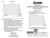
SOCCER GOAL
SIZE: 12Ft.Wide x 6Ft.High x 5Ft.Deep
(3.66 m x 1.83 m x 1.52 m)
1
2
7
8
NEVER CLIMB ON GOAL
Goal Can Fall Over Causing
Serious Injury or Death
RED TAB
RED TAB
BLUE TAB
BLUE TAB
Step Net Assembly Instructions
1. The net has been designed with red tabs to identify the top corners
and blue tabs to identify the bottom corners. Follow the numbered
sequence to attach the net.
2. Using the self-stick closure strips, tie the top corners first which are
identified by the two red tabs. Refer to 1 & 2 .
3. Using the self-stick closure strips, tie the front bottom corners which
are identified by the two blue tabs. Refer to 3 & 4 .
4. Stretch the net and using the self-stick closure strips, tie the back
bottom corners. Refer to 5 & 6 .
5. Fill in the top front section 7 with 4 self-stick strips,
6. Fill in each of the two side sections 8 with 4 self-stick strips,
7. Fill in each of the two base sections 9 with 3 self-stick strips,
8. Fill in the bottom back section 10 with 4 self-stick strips.
9. Fill in each of the two reinforcement sections 11 with 3 self-stick strips.
BEFORE ASSEMBLY:
Work on a smooth, flat surface.
Lay out all components so they are in easy reach.
Read assembly instructions completely to familiarize
yourself with the components.
This goal is designed to provide many hours of enjoyment
if properly assembled and used only for the purpose
intended.
Adult supervision is recommended when the goal is used
by children.
Franklin Sports Inc.
Stoughton, MA. 02072
Made in China
www.franklinsports.com
Figure #3 NET ASSEMBLY
For replacements parts call
1-781-341-5178 or 1-800-225-8649
OR visit www.franklinsports.com
8
4
6
9
10
3
5
9
NOTE: Following goal assembly 6 ground stakes will secure goal.
Refer to sketch for recommended locations
ALWAYS ANCHOR GOAL
Unsecured Goal Can Fall Over
Causing Serious Injury or Death
1111
CAUTION:
Adult assembly required

1 4 L Shaped Tube 8 1/4 in x 47 1/4 in (21 cm x 120 cm)
one end perforated
2 2 Straight Tube 53 in (134.6 cm)
metal snaps on both tapered ends
3 2 Straight Tube 36 7/8 in (93.7 cm)
metal snaps on both tapered ends
4 2 Straight Tube 48 in (1.22 m)
metal snaps on both tapered ends
5 2 L Shaped Tube 8 1/4 in x 31 1/2 in (21 cm x 80 cm)
both ends perforted
6 2 J Shaped Tube 12 1/2 in x 22 5/8 in (30.5 cm x 57.5 cm)
7 2 Straight Tube 35 1/2 in (90.2 cm)
metal snaps on both tapered ends
8 2 Bent Tube 22 7/8 in (58.1 cm)
9 1 Mesh Net 24 ft x 8 ft x 4 in
(7.31 m x 2.44 m x 10.2 cm)
10 6 U Shape Ground 8 in (20.3 cm)
Stake
11 40 Self-Stick Closure 8 in x 3/4 in (20.3 cm x 1.91 cm)
Strips
12 8 Hardware Set metal: screw/washer/wing nut
FIGURE 2B
1
RED TAB RED TAB
BLUE TAB
BLUE TAB
2
3
4
5
6
7
8
9
10
11
12
1
2
3
5
6
7
8
2
4
1
1
3
6
7
8
1
5
4
FIGURE 2A
Figure #2 FRAME ASSEMBLY
Assemble all lengths of tubing shown in Figure 1. Be sure that each piece
is inserted completely. The ends of each tube insert tightly and is secured
when the press button of the tapered end pops through the adjoining
perforated tube.(Figure 2A)
Figure #1 FRAME COMPONENTS
Step Assembly Instructions
1. Assemble the first set of tubes, parts 1 & 2 . This will create the
back base.
2. Insert tapered tubes, part 4 , to the back base. The end with the
two holes needs to be attached closest to the back.
3. Insert L shaped tubes, part 5 , as shown into the side base section
of tubes part(s).
4. Insert tapered tubes, part 3 , into the upward reaching base. The
end with the two holes needs to be at the top.
5. After assembling the second set of tubes, parts 1 & 2 , place
these on the two tapered sections, part 3 , to complete the frame.
6. Assemble the two reinforcement sections by connecting parts
6 , 7 , & 8 . The J shaped section, part 6 , is the upper section
while the bent tube numbered 8 attaches to the base.
7. Align the 2 holes from J tube with the two holes in tube 3 . Using
one set of hardware, insert the screws through the two sets of
tubes from the front. When the screw passes through the two tubes
place the washer on the screw then add the butterfly. Turn the
butterfly clockwise to tighten. Repeat with the 2nd set of hardware.
(Figure 2B)
8. Align the two holes from the bent tube with the two holes in tube 4 .
Using one set of hardware, insert the screws through the two sets of
tubes from the base. When the screw passes through the two tubes
place the washer on the screw then add the butterfly. Turn the
butterfly clockwise to tighten and secure the tubes together. Repeat
with 2nd set of hardware.
6
3
PART QTY DESCRIPTION
/