Page is loading ...

LVDT200 manual (d0018) 1
Texmate, Inc. Tel. (760) 598-9899 www.texmate.com
Input setup mode
• 50or60Hzsupplyfrequency.
• Excitationfrequencies:
50 Hz:1.2,1.6,2.4,3.2,4.8,6.4,8.0,9.6
kHzexcitation.
60 Hz: 1.44, 1.92, 2.88, 3.84, 5.76, 7.68,
9.60,11.52kHzexcitation.
• Updaterates:1,4,10,or20readingsper
second.
• Independentdecimalpointpositionsetting
foreachchanneldisplaywithresolutionto
0.00001ofanyengineeringunit.
Calibration mode
• Independentcalibrationforeachchannel:
Auto Calibration:2-pointzeroandspan
setting.
Offset Trim: Independentlytrim thezero
settingorenteranoffsetvalue.
Span Trim: Independently trim the span
setting.
Analog output mode
• Zerosetting.
• Fullscalesetting.
Setpoints mode
• Fourindependentlyconfiguredsetpoints
with above and below setpoint value
actuation.
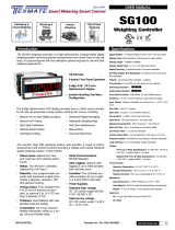
LVDT-200
Dual LVDT Controllers
Positioning & Displacement
Introduction Specifications
• 1/8DINCase
• 6-digit,0.56”(14.2mm)
Alphanumeric Display
• 3-buttonFrontPanel
Operation
• IntuitiveScrollingText
Configuration Menus
General
Digital Display:14-segmentalphanumeric,0.56”(14.2mm)LEDs.
Display Color: Red(standard).GreenorSuper-brightRed(optional).
Display Range:-199999to999999.
Display Update Rate:1,4,10,or20timespersecond.
Display Dimming:8brightnesslevels.Frontpanelselectable.
Scrolling Display Text Messaging: Full alphanumeric text
characterssupported.
Polarity:Assumedpositive.Displays–negative.
Annunciators:6redLEDsonfrontpanel;onepersetpoint.
OverrangeIndication:
Underrange Indication:
FrontPanelControls:PROGRAM,UPandDOWNbuttons.
PowerSupplies. StandardhighvoltageAC/DCpowersupply
85-265VAC/95-300VDC,
50-400Hz,2Wnominal.
oroptional
lowvoltageAC/DCpowersupply14-48VAC/10-72VDC.
Environmental
Operating Temperature: 0to50˚C(32˚Fto122˚F).
Storage Temperature:-20˚Cto70˚C(-4˚Fto158˚F).
RelativeHumidity:95%(non-condensing)at40˚C(104˚F).
Mechanical
Case Dimensions: 1/8DIN,96x48mm(3.78”x1.89”).
Case Depth: 137mmmaximum(5.39”).
Case Material:94V-0ULratedself-extinguishingpolycarbonate.
Weight:11.5oz(0.79lbs),14oz(0.96lbs)whenpacked.
Approvals
UL: E469078
Input Module ISL1
ExcitationVoltage:3VRMSsinewave,zeroDCcomponentTHD
<2%(1.2kHz).
Excitation Frequency: x 16 selectable frequencies available (1.2
kHzto11.5kHz).Crystallocked,softwaredriven.
Temperature Coefficient: ±50ppm/°Coffullscale(typical).
Dual LVDT Inputs: 30kΩinputimpedance.Synchronous
demodulationofexcitationcarrier.>130dbrejectionofexcitation
carrier.
FrequencyResponse:500Hz(–3db)low-passfilter.
Analog to Digital: DualchannelΣΔA/Dconvertorapproaching
19-bitresolution.Ratiometricoperationrelativetoexcitationvoltage
magnitude.
Dual Output Rates: Rapid and average response outputs. 1 Hz,
2Hz,10Hz,20Hzaveraged.
LineFrequencyRejection:50/60Hznoiserejection.
Relay Output Modules
PleaseseePage11.
The LVDT-200 Series are accurate,
high performance, programmable
dual channel controllers that deliver
precise measurement and control
for applications using LVDT (Linear
Variable Differential Transformer)
inputs.
The 6-digit alphanumeric LED
displayprovideseasytofollowsetup
prompts for all LVDT parameters
usingthefollowingintuitivescrolling
textconfigurationmenus.
• Relay
Standard :Four4amprelays.
• Analog Output
Standard:Fullyscalablefrom0/4
to20mA(orreverse).
Options:Single0to10VDC(or
reverse)ordual10–0–10VDC.
AdvancedFunctions
Arangeofbuilt-inmeasurementand
control functions are available with
the LVDT-200 Series controllers’
resident operating system that can
also be programmed from the front
panel.Theseinclude:
• Linearization. Uptofour32-point
flexiblelinearizationtablesora
single125-pointflexibletable.
• SerialCommunications.Optional
singleASCIIorEthernet(TCP/IP)
outputs.
• Differential Measurement.
Differentialmeasurementand
crosschannelmathsavailable
(A+B,A–B,AxB,A/B).
Optimizeperformanceandlinearity.
Selectthecorrectfrequencyforyour
sensor
TIGERFAMILY

2LVDT200 manual (d0018)
Texmate, Inc. Tel. (760) 598-9899 www.texmate.com
P
4 Secs
Input Setup
Start
Prog.
SP1SP2 SP4SP3SP5 SP6
Prog.
SP1 SP2 SP4SP3SP5 SP6
P
Prog.
SP1 SP2SP4SP3 SP5 SP6
P
Calibration
Prog.
SP1SP2 SP4SP3 SP5 SP6
P
P
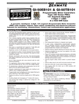
Takes you into Input Setup mode and provides selection for:
• Supply frequency: 50 or 60 Hz.
• One of eight excitation settings for either 50 or 60 Hz.
• One of four output rates.
• Independent decimal point position for channels 1 and 2.
Takes you into Calibration mode and provides selection for:
• Either channel 1 or channel 2 for calibration.
• 2-point auto calibration for zero and span.
• Manual trim for zero offset.
• Manual trim for span.
See Page 3
See Page 4
Prog.
SP1 SP2SP4SP3 SP5 SP6
Prog.
SP1 SP2 SP4SP3SP5 SP6
P
Analog Output Scaling
P
Takes you into Analog Output Scaling mode and provides:
A menu that allows you to set zero and full scale analog output calibration
settings.
See Page 5
P
Setpoints
Prog.
SP1 SP2SP4SP3SP5 SP6
Prog.
SP1 SP2 SP4SP3SP5 SP6
P
Takes you into Setpoint mode and provides:
• Selection of individual setpoints SP1 to SP4.
• Setting of individual setpoint source.
• Setting of individual setpoint activation value.
• Setting of individual setpoint activation ABOVE or BELOW.
P
See Page 6
Allows you to change the displayed value:
• Select either CH1, CH2, CH1+CH2 or CH1-CH2.
See Page 4
P
Select Display
Prog.
SP1SP2 SP4SP3 SP5 SP6
Prog.
SP1 SP2 SP4SP3 SP5 SP6
Table of Contents
Specifications ...........................................1
Introduction.............................................1
IntuitiveScrollingTextMenus...............................2
ViewModes............................................2
ConfigurationMenusLogicTree............................2
InputSetup .............................................3
Calibration.............................................4
AnalogOutputScaling.................................... 5
Setpoints...............................................6
CalibrationModeZeroOptions.............................6
AnalogOutputScalingandCalibrationExample ................7
InputSignalSetupProcedures.............................9
ConnectorPinouts......................................10
Installation............................................12
ApplicationExamples ....................................13
Notes................................................14
IntuitiveScrollingTextMenus
Configuration Menus Logic Tree
After the controller has been powered up, the display settles
andindicates theinput signalcalibratedvalue.This isknown
as the operational mode and is generally referred to as the
throughoutthisdocument.
Intuitivescrollingtextmenusprovidequickaccesstoarange
ofconfigurationmodesforeasyLVDTsensorapplicationsetup.
Thebelowdescribestheconfigurationmenus.
View Modes
The view modes allow easy viewing of the second channel
readingplustotal1andtotal2ifrequired.
P
Prog.
SP1 SP2 SP4SP3 SP5 SP6
Operational Display
Example of
Channel 1
Reading
Prog.
SP1 SP2 SP4SP3 SP5 SP6
Prog.
SP1 SP2 SP4SP3 SP5 SP6
Prog.
SP1 SP2 SP4SP3 SP5 SP6
Prog.
SP1 SP2 SP4SP3 SP5 SP6
Example
of Total 1
Reading
P
Prog.
SP1 SP2 SP4SP3 SP5 SP6
Operational Display
Example of
Channel 2
Reading
Prog.
SP1 SP2 SP4SP3 SP5 SP6
Prog.
SP1 SP2 SP4SP3 SP5 SP6
Prog.
SP1 SP2 SP4SP3 SP5 SP6
Prog.
SP1 SP2 SP4SP3 SP5 SP6
Example
of Total 2
Reading

LVDT200 manual (d0018) 3
Texmate, Inc. Tel. (760) 598-9899 www.texmate.com
Prog.
SP1SP2 SP4SP3 SP5 SP6
P
4 Secs
[_ _ _INPUT
SETUP] Prog.
SP1SP2 SP4SP3 SP5 SP6
P[_ _ _SELECT
SUPPLY
FREQUENCY]
Prog.
SP1 SP2SP4SP3 SP5 SP6
Prog.
SP1SP2 SP4SP3SP5 SP6
YES
YES
START
Prog.
SP1 SP2 SP4SP3SP5 SP6
P
See Page 4 for further details
YES
YES P
Or press the P button 4 times to
EXIT (bypassing the remaining modes)
and return to the Operational Display
Input Setup
Select the required setting
to suit the power supply
frequency. If the mains
supply is 50 Hz, then
select 50 Hz to reject
50 Hz noise. Correspondingly,
if the mains supply is 60 Hz,
then select 60 Hz to reject
60 Hz noise.
P[_ _ _SELECT
EXCITATION
IN KHZ]
OR
Prog.
SP1SP2 SP4SP3SP5 SP6
[ 11.52]
[ 1.92]
[ 2.88]
[ 3.84]
[ 5.76]
[ 7.68]
[ 9.60]
P[_ _ _SELECT
OUTPUT RATE] Prog.
SP1 SP2SP4SP3 SP5 SP6
1 Hz = 1/sec
4 Hz = 4/sec
10 Hz = 10/sec
20 Hz = 20/sec
[_ _ _SELECT
EXCITATION
IN KHZ]
Prog.
SP1 SP2SP4SP3SP5 SP6
[ 1.6]
[ 2.4]
[ 3.2]
[ 4.8]
[ 6.4]
[ 8.0]
[ 9.6]
P
60 Hz Selection
50 Hz Selection
P[_ _ _SELECT DECIMAL POINT CH1]
Prog.
SP1 SP2 SP4SP3SP5 SP6
Select the decimal point position
for the required resolution for CH1:
• 0.1 - Tens.
• 0.12 - Hundreds.
• 0.123 - Thousands.
• 0.1234 - Ten thousands.
• 0.12345 - Hundred thousands.
Prog.
SP1SP2 SP4SP3SP5 SP6
Prog.
SP1SP2 SP4SP3 SP5 SP6
Prog.
SP1 SP2 SP4SP3SP5 SP6
OR
OR YES
YES
P[_ _ _SELECT DECIMAL POINT CH2]
Select the decimal point position
for the required resolution for CH2:
• 0.1 - Tens.
• 0.12 - Hundreds.
• 0.123 - Thousands.
• 0.1234 - Ten thousands.
• 0.12345 - Hundred thousands.
Calibration
[_ _ _SELECT
CALIBRATION
CHANNEL]
[ 0.1]
[ 0.12]
[ 0.123]
[ 0.1234]
[0.12345]
Prog.
SP1 SP2SP4SP3 SP5 SP6
[ 0.1]
[ 0.12]
[ 0.123]
[ 0.1234]
[0.12345]
Select sensor excitation
frequency according to
sensor specification to
optimize performance.
Press the button to enter the Calibration Mode
Input Setup
Theinput setup modeallowsyoutoconfigurefiveinputsetupsettingsinlinkedmenus.

4LVDT200 manual (d0018)
Texmate, Inc. Tel. (760) 598-9899 www.texmate.com
P
P
[_ _ _SELECT CALIBRATION CHANNEL]
Prog.
SP1 SP2SP4SP3SP5 SP6
Prog.
SP1 SP2SP4SP3SP5 SP6
Prog.
SP1 SP2 SP4SP3 SP5 SP6
P
4 Secs
[_ _ _INPUT
SETUP]
START
YES
Input Setup
Calibration
[_ _ _SET SENSOR TO ZERO POSITION
– – – PRESS P BUTTON TO ACCEPT]
P[_ _ _ADJUST LVDT SO DISPLAY READS ZERO]
Adjust the sensor to the known zero position. Adjust
the display value using the buttons. Press the
P button to accept the sensor's new zero position.
Adjust the LVDT core until the LVDT output is zero.
P[_ _ _SET SENSOR TO SPAN POSITION
– – – ENTER SPAN POSITION COUNTS
– – – PRESS P BUTTON TO ACCEPT]
Adjust the sensor to the known span position. Adjust
the display value using the buttons. Press the
P button to accept the sensor's new span position.
ZERO POSITION
Sensor
SPAN POSITION
Sensor
Max counts 999999
Min counts –199999
Prog.
SP1SP2 SP4SP3SP5 SP6
Max counts 999999
Min counts –199999
Prog.
SP1SP2 SP4SP3SP5 SP6
P
Prog.
SP1SP2 SP4SP3SP5 SP6
[_ _ _ENTER ZERO OR OFFSET POSITION
– – – PRESS P BUTTON TO ACCEPT]
Adjust the sensor to the known zero or offset position.
Adjust the display value using the buttons. Press
the P button to accept the sensor's new zero or
offset position.
P
OR
OR
Max counts 999999
Min counts –199999
Prog.
SP1SP2 SP4SP3 SP5 SP6
P
OR
P
Prog.
SP1SP2 SP4SP3SP5 SP6
[_ _ _SET SENSOR TO KNOWN POSITION
– – – ENTER SPAN POSITION COUNTS
– – – PRESS P BUTTON TO ACCEPT]
Set sensor to known span position. Enter span position
counts using the buttons. Press the P button to accept
the sensor's new span position.
Max counts 999999
Min counts –199999
Prog.
SP1 SP2SP4SP3SP5 SP6
P
Analog Output
P
YES
Prog.
SP1 SP2 SP4SP3SP5 SP6
P
[_ _ _SELECT
ANALOG
OUTPUT]
Select Display
[_ _ _SELECT
DISPLAY]
This calibration technique allows you
to independently trim the zero setting,
or enter an offset value without altering
the calibrated span range.
Choose (CH1) to display the LVDT 1 position, (CH2)
to display the LVDT 2 position, (CH 1+2) to display the sum
of LVDTs 1 and 2, or (CH 1-2) to display the difference
of LVDTs 1 and 2.
Prog.
SP1 SP2SP4SP3 SP5 SP6
P
YES
P
[_ _ _SELECT
CALIBRATION
METHOD]
Prog.
SP1SP2 SP4SP3 SP5 SP6
Prog.
SP1 SP2 SP4SP3SP5 SP6
Prog.
SP1SP2 SP4SP3SP5 SP6
P
P
OR
This is a dual zero and span
calibration procedure.
Must bring sensor to NULL
position before calibrating.
This calibration technique allows you
to independently trim the span setting
without altering zero position.
Note, when trimming the span value,
the zero offset value is automatically
recalculated and adjusted for the new
scale factor.
See Page 3 for further details
Press the button to enter the Input Setup mode
See Page 5 for further details
Press the button to enter the Analog Output mode
Or press the P button 2 times to
EXIT (bypassing the remaining modes)
and return to the Operational Display
OR
OR
Prog.
SP1 SP2 SP4SP3SP5 SP6
Prog.
SP1 SP2 SP4SP3SP5 SP6
Prog.
SP1 SP2 SP4SP3SP5 SP6
Prog.
SP1 SP2 SP4SP3SP5 SP6
Prog.
SP1 SP2 SP4SP3SP5 SP6
Prog.
SP1 SP2 SP4SP3SP5 SP6
Prog.
SP1 SP2 SP4SP3SP5 SP6
Prog.
SP1 SP2 SP4SP3SP5 SP6
OR
Calibration
Thecalibration modeprovidesfourindividualcalibrationtechniques.

LVDT200 manual (d0018) 5
Texmate, Inc. Tel. (760) 598-9899 www.texmate.com
Prog.
SP1SP2 SP4SP3SP5 SP6
P
YES
[_ _ _SELECT
CALIBRATION
CHANNEL]
Prog.
SP1 SP2SP4SP3SP5 SP6
P
4 Secs
[_ _ _INPUT
SETUP]
START
YES
Input Setup
Calibration
Analog Output
Prog.
SP1SP2 SP4SP3SP5 SP6
P
Prog.
SP1SP2 SP4SP3SP5 SP6
YES
[_ _ _SELECT
ANALOG
OUTPUT]
Prog.
SP1SP2 SP4SP3SP5 SP6
[_ _ _SET ZERO VALUE]
Max counts 999999
Min counts –199999
Prog.
SP1 SP2SP4SP3SP5 SP6
OR
P
P
P[_ _ _SET FULL
SCALE VALUE]
Max counts 999999
Min counts –199999
Prog.
SP1 SP2SP4SP3SP5 SP6
P[_ _ _SET DATA SOURCE]
Prog.
SP1 SP2SP4SP3SP5 SP6
Prog.
SP1SP2 SP4SP3SP5 SP6
Prog.
SP1SP2 SP4SP3SP5 SP6
P
YES P
[_ _ _SELECT
SETPOINT]
Setpoints
Set the counts required to be displayed for the
calibrated low analog output value using
the buttons. Press the P button to accept the
new low value.
Set the counts required to be displayed for the
calibrated high analog output value
using the buttons. Press the P button to accept
the new high value.
Select either channel 1 (CH1), channel 2 (CH2),
channel 1 plus 2 (CH 1+2) or channel 1 minus 2 (CH 1-2)
as the source of data for the selected analog output.
P[_ _ _CALIBRATE OUTPUT] P
Prog.
SP1 SP2SP4SP3SP5 SP6
Prog.
SP1SP2 SP4SP3SP5 SP6
OR
Analog Output 1
Analog Output 2
Or press the P button to EXIT
and return to the Operational Display
Analog Output Modules:
AIC: Single 0/4-20 mA
AIV: Single 0-10 V DC
ADV: Dual 0-10 V DC
See Page 3 for further details
Press the button to enter the Input Setup mode
See Page 4 for further details
Press the button to enter the Calibration mode
See Page 4 for further details
Press the button to change the Display
See Page 6 for further details
Press the button to enter the Analog Output mode
Prog.
SP1 SP2SP4SP3SP5 SP6
Prog.
SP1 SP2SP4SP3SP5 SP6
Prog.
SP1 SP2SP4SP3SP5 SP6
Prog.
SP1 SP2SP4SP3SP5 SP6
Prog.
SP1 SP2SP4SP3SP5 SP6
P
Select Display
[_ _ _SELECT
DISPLAY]
Prog.
SP1 SP2SP4SP3SP5 SP6
Prog.
SP1 SP2SP4SP3SP5 SP6
1)
Analog Output Scaling
The analog output module is a standard single channel,
programmable,isolated,16-bitanalogoutputthatcanbescaled
toanydesiredspanbetween–199999to999999displaycounts
usingthe.
Optional single channel 0-10 V DC and dual channel 10–0–10
V DC analog output modules are also available.
SeeAnalog Output Proceduresforananalogoutputscaling
procedure.
SeeAnalog Output Proceduresforananalogoutputsignal
calibrationprocedure.
SeeAnalog Output Proceduresforacurrent/voltage
selectionheaderpositioningprocedure.
1)

6LVDT200 manual (d0018)
Texmate, Inc. Tel. (760) 598-9899 www.texmate.com
Setpoints
Thesetpoint modeprovidessettingsforsixindividualsetpoints.
Prog.
SP1 SP2SP4SP3SP5 SP6
YES P
Prog.
SP1 SP2 SP4SP3 SP5 SP6
P
YES
[_ _ _SELECT
CALIBRATION
CHANNEL]
Prog.
SP1SP2 SP4SP3 SP5 SP6
P
4 Secs
[_ _ _INPUT
SETUP]
START
YES
Input Setup
Calibration
Analog Output
Prog.
SP1 SP2 SP4SP3 SP5 SP6
P
YES P
[_ _ _SELECT
ANALOG
OUTPUT]
Prog.
SP1 SP2SP4SP3SP5 SP6
PProg.
SP1 SP2SP4SP3SP5 SP6
YES P
[_ _ _SELECT
SETPOINT] P
Setpoints
Prog.
SP1 SP2 SP4SP3SP5 SP6
Prog.
SP1 SP2 SP4SP3SP5 SP6
Prog.
SP1 SP2 SP4SP3 SP5 SP6
Prog.
SP1 SP2SP4SP3SP5 SP6
Prog.
SP1 SP2SP4SP3 SP5 SP6
Prog.
SP1 SP2SP4SP3 SP5 SP6
YES P
[_ _ _SET SETPOINT SOURCE]
Prog.
SP1SP2 SP4SP3SP5 SP6
Prog.
SP1SP2 SP4SP3SP5 SP6
Prog.
SP1 SP2SP4SP3 SP5 SP6
Prog.
SP1 SP2SP4SP3 SP5 SP6
Prog.
SP1 SP2SP4SP3 SP5 SP6
Prog.
SP1 SP2SP4SP3 SP5 SP6
P[_ _ _SET SETPOINT VALUE]
Max counts 999999
Min counts -199999
Prog.
SP1 SP2SP4SP3 SP5 SP6
Prog.
SP1SP2 SP4SP3SP5 SP6
Prog.
SP1SP2 SP4SP3SP5 SP6
P[_ _ _SET SETPOINT
ACTIVATION]
YES
YES
YES
YES
OR
OR
OR
OR
OR
OR
OR
YES
YES
Setpoints Activation Values:
SP1: 18000
SP2: - 18000
SP3: 5000
SP4: - 5000
See Page 3 for further details
Or press the P button to EXIT and
return to the Operational Display
Press the button to enter the Input Setup mode
See Page 4 for further details
Press the button to enter the Calibration mode
See Page 5 for further details
Press the button to enter the Analog Output mode
DMC-A2 Series controllers
have up to 4 switched outputs
available in various formats.
Plug-in relay output modules provide
up to 4 relay outputs using 5 A relays.
Select the setpoint
to be configured
Select a channel as the source
for setpoint activation.
Set the setpoint value
using the buttons.
Set each setpoint to
activate above or below
the setpoint value.
SP SP
ACTIVATION
BELOW
ABOVE
See Page 4 for further details
Press the button to change the Display
P
Select Display
[_ _ _SELECT
DISPLAY] Prog.
SP1 SP2 SP4SP3 SP5 SP6
Prog.
SP1 SP2 SP4SP3 SP5 SP6
Calibration Mode Zero Options
NULL
The NULLposition allows the user to adjust the LVDT core
until the LVDT output is zero. The sensor must be brought to
NULLpositionbeforecalibrating.
The controller has been programmed with a and function that
operatesontheselectedprimarydisplayreadingonly.
Thefunctionisusedtozerothedisplay.Displayzeroisinitiated
from a remote switch (not supplied) connected across the and
pinsattherearofthecontroller(Terminal2:Pin4Common,Pin
2Hold).
Thefunction is used to restore the true calibrated valueonthe
display. Reset display value is initiated from a remote switch
connected across the and pins at the rear of the controller
(Terminal2:Pin4Common,Pin1Lock).
Thedisplayzerovalueandreset displayvaluearenotretained
duringapoweroutage.
Thedisplayzeroandresetdisplayvaluefunctionsareoftenused
forcut,measure,andtrimapplications.

LVDT200 manual (d0018) 7
Texmate, Inc. Tel. (760) 598-9899 www.texmate.com
Prog.
SP1 SP2SP4SP3SP5 SP6
Example
To
Step
7
From Step 6
Press
1
Step 1
Enter the
Configuration
Menus
Prog.
SP1 SP2SP4SP3SP5 SP6
Operational Display
Press
for 4
secs
Prog.
SP1 SP2SP4SP3SP5 SP6
Prog.
SP1 SP2SP4SP3SP5 SP6
Prog.
SP1 SP2SP4SP3SP5 SP6
Press
3
[_ _ _ INPUT SETUP]
Step 2
Display scrolls
Press the button
three times to skip
the Calibration
and Display Select
modes enter the
Analog Output
mode
P
Prog.
SP1 SP2SP4SP3SP5 SP6
Prog.
SP1 SP2SP4SP3SP5 SP6
Prog.
SP1 SP2SP4SP3SP5 SP6
[_ _ _ SELECT
ANALOG OUTPUT]
Step 3
Display scrolls
Press the button
once to enter
Analog Output 1
or twice to enter
Analog Output 2
Step 4
Confirm Analog
Output Selection.
Prog.
SP1 SP2SP4SP3SP5 SP6
Press
1
Example
Prog.
SP1 SP2SP4SP3SP5 SP6
Prog.
SP1 SP2SP4SP3SP5 SP6
Prog.
SP1 SP2SP4SP3SP5 SP6
Step 5
Adjust the display to 50
counts for the low analog
output scale setting
[_ _ _ SET ZERO VALUE]
Display scrolls
OR
Step 6
Accept the new
low value
Prog.
SP1 SP2SP4SP3SP5 SP6
Prog.
SP1 SP2SP4SP3SP5 SP6
Prog.
SP1 SP2SP4SP3SP5 SP6
Adjust the display to 30,000
counts for the high analog
output scale setting
[_ _ _ SET FULL SCALE
VALUE]
Step 7
Display scrolls
OR
Step 8
Accept the new
high value
Prog.
SP1 SP2SP4SP3SP5 SP6
Prog.
SP1 SP2SP4SP3SP5 SP6
Prog.
SP1 SP2SP4SP3SP5 SP6
OR
Step 10
Accept the new
data source
setting.
Prog.
SP1 SP2SP4SP3SP5 SP6
Example
Press
1
Step 9
[_ _ _ SET DATA SOURCE]
Display scrolls
Press the button
once to select Channel 1
or twice to select
Channel 2
Prog.
SP1 SP2SP4SP3SP5 SP6
Example
Press
1
Step 11
[_ _ _ CALIBRATE OUTPUT]
Display scrolls
Press the button
to skip Output Calibration
and return to Step 3.
Press the button
twice to return to the
Operational Display
P
Prog.
SP1 SP2SP4SP3SP5 SP6
Prog.
SP1 SP2SP4SP3SP5 SP6
Press
1
P
Prog.
SP1 SP2SP4SP3SP5 SP6
OR
The calibration of the
Analog Output is continued on page 8
AnalogOutputScalingandCalibrationExample
Inthisexampletheanalogoutputsignalisscaledoverarangeof
50to30,000counts.Theanalogoutputisthencalibratedfora0
to10VDCoutput.
1) Connect a multimeter to the analog output connector at the
rearofthemeter(Terminal4:Pin3positive,Pin2negative).
2) Makesurethemultimeterissettoreadtheappropriatesignal
type:voltsormilliamps.
3) Carryouttheanalogoutputscalingproceduretosetzeroand
fullscalesettings.
4) Ifrequired,carryouttheanalogoutputcalibrationprocedureto
calibratethemilliamp(orvoltage)outputlowandhighsettings.
Note:
In Steps 11 to 19, the analog output may be calibrated to other
ranges such as 0-20 mA or 4-20 mA. For current output the header on
the analog output module has to be moved to the CURRENT position.
See the drawing on Page 8 on how to change the analog output from
voltage (default) to a current output.
Scaling the Analog
Output Signal
START HERE
Scaling of the Analog
Output Signal is now
complete

8LVDT200 manual (d0018)
Texmate, Inc. Tel. (760) 598-9899 www.texmate.com
Prog.
SP1 SP2SP4SP3SP5 SP6
Prog.
SP1 SP2SP4SP3SP5 SP6
Prog.
SP1 SP2SP4SP3SP5 SP6
Prog.
SP1 SP2SP4SP3SP5 SP6
Prog.
SP1 SP2SP4SP3SP5 SP6
Prog.
SP1 SP2SP4SP3SP5 SP6
Prog.
SP1SP2 SP4SP3SP5 SP6
Prog.
SP1 SP2SP4SP3SP5 SP6
Prog.
SP1 SP2SP4SP3SP5 SP6
Prog.
SP1 SP2SP4SP3SP5 SP6
OR
Prog.
SP1 SP2SP4SP3SP5 SP6
Prog.
SP1 SP2SP4SP3SP5 SP6
Prog.
SP1 SP2SP4SP3SP5 SP6
DO NOT CHANGE
THIS SETTING.
Prog.
SP1 SP2SP4SP3SP5 SP6
Prog.
SP1 SP2SP4SP3SP5 SP6
Prog.
SP1 SP2SP4SP3SP5 SP6
Prog.
SP1 SP2SP4SP3SP5 SP6
X
Press
at same
time
Press
at same
time
To
Step
17
Step 17
X
OR
Press
1
Ensure the high analog output
signal reading [CAL_HI] on
the multimeter display is
10.00 V DC.
MULTIMETER
V
V
mV
mA
A
OFF
µA
COM V
mA µA
A
PEAK MIN MAX
MIN MAX RANGEHOLD
Hz
REL
–
+
MULTIMETER
V
V
mV
mA
A
OFF
µA
COM V
mA µA
A
PEAK MIN MAX
MIN MAX RANGEHOLD
Hz
REL
–
+
Pin 3+
Pin 2–
TERMINAL 4
Pin 3+
Pin 2–
TERMINAL 4
[___PRESS P
AND UP]
Step 12
Display scrolls
Press and
buttons at the
same time
P
X
Step 13
Press to enter the
Calibration menu
P
Press
at same
time
Press
at same
time
Step 18
Press button
to leave the CAL
menu
Press and buttons at
the same time to return to
the operational display
P
P
Step 14
With DMC-A2 Series connected
to a multimeter, DMC-A2 Series
displays [CAL] [151]. This
is the setting for analog
output 1 ([CAL] [152] for
analog output 2).
Press to start the
calibration procedure
P
Press
1
Step 19
Ensure the low analog
output signal reading
[CAL_LO] on the
multimeter display
is 0.00 V DC.
If not correct, press
the or button on
DMC-A2 Series until
the reading on the
multi meter display is
correct.
Step 15
Step 16
Press to save the
low analog output
signal setting. Enter
analog output high
X
Example
MULTIMETER
V
V
mV
mA
A
OFF
µA
COM V
mA µA
A
PEAK MIN MAX
MIN MAX RANGE HOLD
Hz
REL
–
+
MULTIMETER
V
V
mV
mA
A
OFF
µA
COM V
mA µA
A
PEAK MIN MAX
MIN MAX RANGEHOLD
Hz
REL
–
+
Press
1
Pin 3+
Pin 2–
TERMINAL 4
Pin 3+
Pin 2–
TERMINAL 4
Prog.
SP1 SP2SP4SP3SP5 SP6
Prog.
SP1 SP2SP4SP3SP5 SP6
Prog.
SP1 SP2SP4SP3SP5 SP6
Press
1
From Step 16
If not 10.00 V DC, press
the OR button on
DMC-A2 Series until the
reading on the multimeter
display is correct.
Prog.
SP1 SP2SP4SP3SP5 SP6
Operational Display
P
Analog Output Module PCB
Currentor
Voltage
Selection
Header
CURRENT
Position
VOLTAGE
Position
AvailableinSingle(0~4-20mAor0-10V)orDual(0-10V&0-10V)
Tochangetheanalogoutputfromvoltagetocurrentoutput,
removethePCBfromthecase.
IdentifytheAnalogOutputmodulewhichissolderedontothetop
carrierboard.
MovetheV/Iselectionheaderontheanalogoutputmodulefrom
thevoltageposition(default)tothecurrentposition.

LVDT200 manual (d0018) 9
Texmate, Inc. Tel. (760) 598-9899 www.texmate.com
+ SIGNAL 1
— EXC
+ EXC
SHIELD
CONTROL 2
CONTROL 1
GND
+ 24 V RELAY
ISOLATED
EXTERNAL
CONTROL
— SIGNAL 1
+ SIGNAL 2
— SIGNAL 2
LVDT 2
LVDT 1
+ 24 V
34
IN 1
IN 2
IN 3
IN 4
IN 5
IN
IN
IN
IN
IN 1
IN 11
ISOLATED
EXTERNAL
CONTROL
+ 24 V RELAY
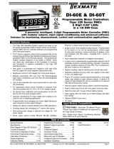
Figure3–ExampleConnectionConfiguredforDualLVDTInputsandTwoRelayOutputs
Configured for dual input LVDTs.
Fast setpoint control outputs activate two +24 V
relay coils (SP5 and SP6).
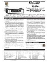
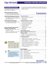
Figure2–ISL1LVDTFunctionalSchematic
HIGH SPEED
SETPOINT
OUTPUTS
LVDT 2
LVDT 1
— 5 V
GND
GND
+ 5 V
+ 24 V
+ SIGNAL 1
—SIGNAL 1
+ SIGNAL 2
—SIGNAL 2
SHIELD
3 V RMS
+ EXC
— EXC
CONTROL 1
CONTROL 2
+24V
Synchronous
Demodulator
500 Hz
LPF
500 Hz
LPF
CH1
CH2
PCB 345
Interface
I2C Bus
16 Programmable
Excitation Frequencies
Dual
hannel
1t
TD
cro
controller
udo
Sne ae
enerator
SP5
SP6
Technical Description
Thisinputisasmartinputmoduledesigned
todriveandconditionthesignalsfromtwo
LVDT transducers. The module contains
two high-speed microcontrollers and a
SD 16-bit dual channel A/D convertor.
It communicates with the selected
controllerviatheI2Cdatabus.Oneofthe
microcontrollersgeneratesthesinewave
fortheLVDTexcitationfrequency.These
frequencies are produced as multiples
ofthelinefrequency (either50 Hzor 60
Hz). Up to 16 frequencies are available
and are selected using the controller
setup. The output to the primary coil of
bothLVDTsisa3VRMSsinewave.The
receivedLVDTsignalsaresynchronously
demodulated and filtered to remove
the carrier frequency. The Σ Δ 16-bit
A/D convertor has over 130 dB noise
rejectionattheexcitationfrequenciesand
is capable of 40 Hz averaged output on
45samples.
Two open collector NPN transistors
are available as high-speed controlled
outputs. The controller setpoint SP5
controls output CONTROL 1 and SP6
andcontrolsoutputCONTROL2.
Table1: ISL111-pinI/OConnector
Pin Description Function
1
2
3
4
5
6
7
8
9
10
11
+Signal 1
–Signal1
–EXC
+EXC
+Signal2
–Signal2
+24V
Control 1
Control 1
Ground
Shield
LVDT1inputsignal+
LVDT1inputsignal–
DualLVDTexcitationsinewave
(1-11kHz).
LVDT2inputsignal+
LVDT2inputsignal–
Excitationvoltage+24V,150mA.
OpencollectorNPNsetpointoutput(600mA).
OpencollectorNPNsetpointoutput(600mA).
0 V.
Cableshield,3Vcommonmode.
Input Signal Setup Procedures
ExampleConnectionDiagram

10 LVDT200 manual (d0018)
Texmate, Inc. Tel. (760) 598-9899 www.texmate.com
14 15
8910 11
Input Module
12
Output Module
Function Pins
LOCK HOLD TEST COM CAPTURE
TERMINAL 1
TERMINAL 6
1
TERMINAL 2
TERMINAL 4
TERMINAL 5
POWER
2345678910 11
32 31 30 29 28 27 26 25 17 16
22 21 20
23
18
Dual Analog
Output ONLY
1924
Serial Output
Analog Output
Connector Pinouts
LVDT-200 Series use plug-in type screw terminal connectors
for most input and output connections, an RJ-11 phone
connector for the RS-232 serial output and an RJ-45 phone
connectorfortheoptionalEthernetoutput.
All external connections to the LVDT-200 Series are via the
following six connector terminal blocks located at the rear of
thecontroller:
• Terminal1: InputSignals.
• Terminal2: FunctionPins.
• Power: AC/DCPowerSupply.
• Terminal4: AnalogOutput.
• Terminal5: SerialOutput.
• Terminal6: RelayOutputorMulti-I/OModule.
WARNING: AC and DC input signals and power supply
voltages can be hazardous. Do not connect live wires to
screwterminal plugs, and do not insert, remove, or handle
screwterminalplugswithlivewiresconnected.
Figure4–RearPanelPinoutDiagram
Pin Name Description
Connector
8
Input Signals
ResetDisplay
Value(Lock)
TERMINAL1
TERMINAL2
FunctionPins
9 DisplayZero
(Hold)
ByconnectingPin5(capture)toPin4(common)witharemotespring-returnswitchmanually
resetsthecalibratedzero.
10
ManualZero
(Capture)
Pin 3 (display test and reset pin) provides a test of the controller’s display and resets the
microprocessorwhenPin3isconnectedtoPin4.
11
DisplayTestand
Reset
Toactivatethehold,test andreset,orlockpinsfromtherearofthecontroller,therespective
pinshavetobeconnectedtothecommonpin.
12
Common
14 ACNeutral/DC–
POWER
Auto Sensing
AC/DCPower
Supply
The power connector suppliesAC / DC power to the controller via a standard high voltage or
optionallowvoltageauto-sensingpowersupplymountedonthemainboard.
PS1: StandardHighVoltageoption.85-265VAC/95-370VDC.
PS2: OptionalLowVoltageoption.14-48VAC/10-72VDC.
15 ACLine/DC+
Pins1upto11
Pins8to12
Pins14and15
Forfurtherdetailsonthefunctionpins,contactTexmate.
1 +Signal1
2 –Signal1
3
+Signal2
4
–Excitation
5
+Excitation
6
Control1
7
–Signal2
8
+24V
+ SIGNAL 1
— EXC
+ EXC
SHIELD
CONTROL 2
CONTROL 1
GND
— SIGNAL 1
+ SIGNAL 2
— SIGNAL 2
+ 24 V
3
4
5
PIN 1
PIN 2
PIN 3
PIN 4
PIN 5
PIN 6
PIN 7
PIN 8
PIN 9
PIN 10
PIN 11
Input Module ISL1
Byconnecting Pin1 (lock) to Pin 4 (common) witha remotespring-return switchrestores the
displaytothetruecalibratedvalue.
By connecting Pin 2 (hold) to Pin 4 (common) with a remote spring-return switch zeroes the
display.
9
Shield
10
Control2
11
Ground

LVDT200 manual (d0018) 11
Texmate, Inc. Tel. (760) 598-9899 www.texmate.com
Pin No.
19
20
21
22
23
24
RS-232 RS-485
Reserved for future use
RXD. Received Serial
TXD. Transmitted Serial
+5 VDC to power external converters
Isolated Ground
Reserved for future use
B (Low)
A (High)
+5 VDC to power external converters
Isolated Ground
Reserved for future use
Reserved for future use
18 Positive(+)
TERMINAL4
Analog Outputs
PositiveforAnalogOutput2(ADV–Dual10–0–10VDCmodulesonly).
17 Negative(–) NegativeforAnalogOutput1and2.
TERMINAL5
Serial Outputs
TERMINAL6
Relay
Outputs
TERMINAL 6 connects electromechanical and
solidstaterelays(SSRs)toexternalapplications.
Pins16to18
Pins19upto24
TERMINAL5connectstheserialoutputmoduletoexternaldevices.
The standard carrier board supports a single or dual RS-232 or RS-485ASCII or
ModbusserialcardconnectedthruanRJ-11socket.
Ethernet
TERMINAL4connectstheanalogoutputmoduletoexternaldevices.Asingle0~4to20mA(standard)or(optional)0to10VDCor
dual10–0–10VDCissupportedonthestandard,Ethernet,orDeviceNETcarrierboard.
Pin Name Description
Connector
Relay Module
Depending on the number of relays, standard
plug-inrelayboardsuseupto8pins.
16 Positive(+) PositiveforAnalogOutput1.
Ethernet–TheEthernetcarrierboardhasthesameanalogoutputpins,
with10/100Base-TEthernet(RJ-45Socket).
32 31 30 2829 27 26 25
Options
4A
Order Code
OR11
OR12
- -
-
10A -
-
SP2 SP4 SP1 SP3
9A9A
7A
SP3SP1SP4SP2
32 31 30 2829 27 26 25
Options
Order Code
OR32
OR34
- -
5A5A 5A 5A
5A 5A
SP4 SP3 SP2 SP1
SP1SP2SP3SP4
32 31 30 2829 27 26 25
Options
Order Code
OR54 210mA210mA210mA210mA
SP4 SP3 SP2 SP1
SP4 SP3 SP2 SP1

12 LVDT200 manual (d0018)
Texmate, Inc. Tel. (760) 598-9899 www.texmate.com
Installation
Installation Guidelines
96 mm
(3.78")
48 mm
(1.89")
3.9 mm
(0.15") typical
FRONT VIEW
1/8 DIN 96x48mm
The 96x48 mm case is
particularly suitable for
mounting in mosaic panels
or insulative panels up to 2"
thick. They can also stack
mount, 2 up in existing
cutouts for 1/4 DIN (96x96
mm) or 4 up in 1/2 DIN
(96X192 mm).
40.8 mm
(1.61")
117 mm
(4.61")
SIDE VIEW
5.3 mm
(0.21")
3.7 mm
(0.15")
43.4 mm
(1.71")
DIN Cutout spacers
Straight-thru Connector for
meters with output board
20 mm (0.79")
Right-angled Connector
11.8 mm (0.47")
PANEL CUTOUT
Case will mount in standard 1/8 DIN coutouts
45 mm
(1.77")
Snug Fitting
Mosaic Fitting
92 mm
(3.62")
Loose Fitting
91.6 mm
(3.6")
40.8 mm
(1.61")
8 places
3 12")
8 places
4 mm
(0.16") 43.4 mm
(1.71")
1/8 DIN
Cutout spacers
87.4 mm
(3.45")
Panel adaptor plates are
available to retrofit most
existing panel cutouts.
For additional strength, extra Mounting
Slide Clips can be ordered and doubled up
one behind the other. P/N: (75-DMTCLIPF)
TOP VIEW
87.4 mm
(3.45")
mosaic
fitting
95.4 mm
(3.77")
Max. panel thickness
50mm
(1.97")
96 mm
(3.78")
91.6 mm
(3.6")
DIN
Cutout
Spacer
To open rear cover,
use a small flat
blade screw driver.
Press down lightly to
release catch on top
or bottom of case
and lever outwards.
4.7 mm
(0.19")
DIN Cutout Spacer
2 mm
(0.08")
Connector
Socket
Prog. SP1
SP1 SP2 SP4SP3SP5 SP6
Prog. SP1
SP1 SP2 SP4SP3 SP5 SP6
Prog.
SP1SP2 SP4SP3SP5 SP6
96x48 SG100.eps
STEP A Prepare the Panel
1) Cutaholeinthepaneltosuitthepanel
cutout.Seepanelcutoutsizesabove.
STEP B Install the Meter
1) Removebothmountingclipsfromthemeter.
2) Pushthemeterintothepanelcutoutfromthe
frontofthepanel.
3) Attachbothmountingclipstothemeterfrom
therearofthepanelandpushthemtowards
thefrontofthepaneluntilthemeterisfirmly
held.
STEP C Connect the Cables
1) Connectallinputandoutputsignalcablestothe
connectorpins(SeeConnector Pinoutsfordetails).
2) Connectthepowercablestotheconnectorpins
(SeeConnector Pinoutsfordetails).
WARNING
ACandDCpowersupplyvoltages
are hazardous. Make sure the
power supply is isolated before
connectingtothemeter.
123
Installation Procedure
1
2
3
Figure5–LVDT-200-100InstallationSequence
Installation
1. Install and wire meter per local applicable codes/
regulations, the particular application, and good
installationpractices.
2. Install meter in a location that does not exceed the
maximumoperatingtemperatureandthatprovidesgood
aircirculation.
3. Separate input/output leads from power lines to
protect the meter from external noise. Input/output
leads should be routed as far away as possible from
contactors,controlrelays,transformersandothernoisy
components.Shieldingcablesforinput/outputleadsis
recommended with shield connection to earth ground
nearthemeterpreferred.
4.A circuit breaker or disconnect switch is required to
disconnect power to the meter. The breaker/switch
shouldbeincloseproximitytothemeterandmarkedas
thedisconnectingdeviceforthemeterormetercircuit.
Thecircuitbreakerorwallswitchmustberatedforthe
appliedvoltage(e.g.,120VAC or 240VAC)andcurrent
appropriate for the electrical application (e.g., 15A or
20A).
5. See Case Dimensions section for panel cutout
information.
6.SeeConnector Pinouts sectionforwiring.
7. Use 28-12 AWG wiring, minimum 90˚C (HH)
temperaturerating.Stripwireapproximately0.3in.(7-8
mm).
8.Recommendedtorqueonallterminalplugscrewsis
4.5lb-in(0.51N-m).

LVDT200 manual (d0018) 13
Texmate, Inc. Tel. (760) 598-9899 www.texmate.com
ApplicationExamples
LVDT 1
LVDT 2
Operational Display (CH1)
Prog.
SP1SP2 SP4SP3SP5 SP6
1
2
CH2 View Mode
Prog.
SP1SP2 SP4SP3SP5 SP6
ALIGNMENTTOOL
MeasuredusingtwoLVDTsensorsat90°
LVDT1toCH1=ShownonDisplay
LVDT2toCH2=UseViewModetoviewCH2
LVDT 1
LVDT 2
Prog.
SP1SP2 SP4SP3SP5 SP6
2
1
Operational Display
showing result of
signal 1 – signal 2
SLOPEINDEXING
MeasuredusingtwoparallelLVDTsensors(1–2)
LVDT1minusLVDT2=DisplayedResult
Note:
This is an advanced function and is configured in
Code 1 of the main programming mode.
LVDT 1
LVDT 2
Operational Display
showing result of
LVDT 1 + LVDT 2
Prog.
SP1SP2 SP4SP3SP5 SP6
1
2
THICKNESSMONITORING
MeasuredusingtwoopposedLVDTsensors(1+2)
LVDT1plusLVDT2=DisplayedResult
Note:
This is an advanced function and is configured in
Code 1 of the main programming mode.
LVDT sensors can be applied in almost all
engineering applications covering civil,
mechanical, petrochemical, power generation,
production, aerospace, defense, and much
more.
They can be used on production lines to
automaticallygaugeproductsforqualitycontrol
andproductsorting.
In the power generation and petrochemical
industries they can be used, for example, as
servopositionfeedbackonactuatedequipment
suchasvalvesanddampers,orformeasuring
turbinecasingexpansion.
Submersibleunits can be used inmarine and
offshoreminingapplications,sensorsthatmeet
military environmental standards have been
appliedtodefenseandaerospaceapplications.
Following are applications that show the
versatilityoftheLVDT-200Seriescontroller.

14 LVDT200 manual (d0018)
Texmate, Inc. Tel. (760) 598-9899 www.texmate.com
Frequency Range:
Standard Display:
Excitation Frequency:
LVDT Output Rate in kHz:
Decimal Point Position:
Input Signal
Zero:
Span:
Analog Output Signal
CAL_LO:
CAL_HI:
Calibration
Zero:
Full Scale:
Scale Range
CH 1
A_OUT1
CH 2
CH 1 CH 2
A_OUT2
Notes

LVDT200 manual (d0018) 15
Texmate, Inc. Tel. (760) 598-9899 www.texmate.com
Setpoints
SP1:
SP2:
SP3:
SP4:
Source Value Activation
Notes

16 LVDT200 manual (d0018)
Texmate, Inc. Tel. (760) 598-9899 www.texmate.com
WARRANTY
Texmatewarrantsthatitsproductsarefreefromdefectsinmaterialandworkmanshipunder
normaluseandserviceforaperiodofoneyearfromdateofshipment.Texmate’sobligations
underthiswarrantyarelimitedtoreplacementorrepair,atitsoption,atitsfactory,ofanyof
theproductswhichshall,withintheapplicableperiodaftershipment,bereturnedtoTexmate’s
facility, transportation charges pre-paid, and which are, after examination, disclosed to the
satisfactionof Texmate tobethus defective.The warrantyshallnot applyto any equipment
which shall have been repaired or altered, except by Texmate, or which shall have been
subjectedto misuse,negligence,oraccident.In nocase shallTexmate’sliabilityexceed the
original purchase price. The aforementioned provisions do not extend the original warranty
periodofanyproductwhichhasbeeneitherrepairedorreplacedbyTexmate.
USER’S RESPONSIBILITY
Wearepleasedtooffersuggestionsontheuseofourvariousproductseitherbywayofprinted
matterorthrough direct contact withoursales/application engineering staff.However,since
we have no control over the use of our products once they are shipped, NO WARRANTY
WHETHEROF MERCHANTABILITY,FITNESSFOR PURPOSE,OR OTHERWISEis made
beyondtherepair,replacement,orrefundofpurchasepriceatthesolediscretionofTexmate.
Usersshalldetermine thesuitabilityof theproductfor theintendedapplication beforeusing,
and the users assume all risk and liability whatsoever in connection therewith, regardless
of any of our suggestions or statements as to application or construction. In no event shall
Texmate’sliability,inlaworotherwise,beinexcessofthepurchasepriceoftheproduct.
Texmatecannotassumeresponsibilityforanycircuitrydescribed.Nocircuitpatentorsoftware
licenses are implied. Texmate reserves the right to change circuitry, operating software,
specifications,andpriceswithoutnoticeatanytime.
450 State Place • Escondido, CA 92029
Tel: 1-760-598-9899 • USA 1-800-839-6283 • 1-800-TEXMATE
Fax: 1-760-598-9828 • Email: [email protected] • Web: www.texmate.com
Forproductdetailsvisitwww.texmate.com
Local Distributor Address
Copyright © 2018 Texmate Inc. All Right Reserved.
/