Page is loading ...

www.vmacair.com
Installation Manual for VMAC
System
V910040
2023+ Ford Super Duty F250 – F600
6.7 L Diesel
UNDERHOODUNDERHOODUNDERHOOD
UNDERHOOD
505050
50
111
1
TMTMTM
TM
AIR COMPRESSORS


VMAC - Vehicle Mounted Air Compressors
VMAC Technical Support: 888-241-2289
VMAC Knowledge Base: kb.vmacair.com
1
Table of Contents
Safety ..............................................................3
Warranty ...........................................................4
Preparing for Installation ............................................8
Relocating the ABS Hydraulic Control Unit (HCU) ...................14
Modifying the Hoses, Installing the Cooler .........................21
Modifying the Fan Shroud and Fan Stator ......................... 28
Installing the Main Bracket, Idler Bracket and Compressor ......... 32
Installing the Air Oil Separator Tank (AOST) ....................... 40
Hose Requirements ............................................... 43
Routing and Connecting the Hoses ............................... 44
Relocating the Battery ............................................ 48
Modifying and Installing Charge Air Cooler and Washer Bottle. .... 54
Adding Oil to the System ......................................... 59
CAC and Hoses ................................................... 60
Installing the Control Components ................................ 69
Completing the Installation ....................................... 75
Recommended Accessories ........................................78
Air Receiver Tank...................................................79
Testing the Installation ............................................ 80
Performance Testing and System Adjustments ..................... 83
Digital Throttle Control Operation and Adjustments ............... 84
Accessory Products from VMAC ....................................87
Warranty Registration ............................................. 92

VMAC - Vehicle Mounted Air Compressors
VMAC Technical Support: 888-241-2289
VMAC Knowledge Base: kb.vmacair.com
2
Additional Application Information
• 2023+ Ford Super Duty F250 – F600, 6.7 L Diesel.
• Passenger side running board is only compatible when the Air Oil Separator Tank is
mounted in the “midship location”, see VMAC knowledge base article:
EXT-ACC-002.
Registered Trademarks
All trademarks mentioned in this manual are the property of their respective
owners. VMAC’s use of manufacturers’ trademarks in this manual is for
identification of the products only and does not imply any affiliation to, or
endorsement of said companies.
Loctite®, Loctite® 242 and Loctite® 567 are registered trademarks of Henkel AG &
Company KGaA.
Posi-TapTM is a trademark owned by Swenco® Products, Inc.
Eaton Aeroquip® is a registered trademark of EATON AEROQUIP INC.
Ford® and Super Duty® are registered trademarks of Ford Motor Company.
Document: 1930473
Changes and Revisions
Revision Revision Details Revised by
Checked by
Implemented
Eng. Tech. Qual.
Mech. Elec.
AInitial release MSP CAM ASE MSP TPK 29 MAY 2023
Important Information
The information in this manual is intended for certified VMAC installers who
have been trained in installation and service procedures and/or for anyone with
mechanical trade certification who has the tools and equipment to properly and
safely perform the installation or service. Do not attempt installation or service
without the appropriate mechanical training, knowledge and experience.
Follow all safety precautions. Any fabrication for correct fit in modified vehicles
must follow industry standard “best practices”.
Notice
Copyright © 2023 VMAC Global Technology Inc. All Rights Reserved. These
materials are provided by VMAC for informational purposes only, without
representation or warranty of any kind, and VMAC shall not be liable for errors
or omissions with respect to the materials. The only warranties for VMAC
products and services are those set forth in the express warranty statements
accompanying such products and services, if any, and nothing herein shall be
construed as constituting an additional warranty. Printing or copying of any page
in this document in whole or in part is only permitted for personal use. All other
use, copying or reproduction in both print and electronic form of any part of this
document without the written consent of VMAC is prohibited. The information
contained herein may be changed without prior notice.
Printed in Canada

VMAC - Vehicle Mounted Air Compressors
VMAC Technical Support: 888-241-2289
VMAC Knowledge Base: kb.vmacair.com
3
Safety
Important Safety Notice
The information contained in this manual is based on sound engineering principles,
research, extensive field experience and technical information. Information
is constantly changing with the addition of new models, assemblies, service
techniques and running OEM changes. If a discrepancy is found in this manual,
contact VMAC Technical Support prior to initiating or proceeding with installation,
service or repair. Current information may clarify the issue. Anyone with knowledge
of such discrepancies, who proceeds to perform service and repair, assumes all
risks.
Only proven service procedures are recommended. Anyone who departs from the
specific instructions provided in this manual must first ensure that their safety and
that of others is not being compromised, and that there will be no adverse effects
on the operational safety or performance of the equipment.
VMAC will not be held responsible for any liability, consequential damages, injuries,
loss or damage to individuals or to equipment as a result of the failure of anyone
to properly adhere to the procedures set out in this manual or standard safety
practices.
Safety should be the first consideration when performing any service operations.
If there are any questions concerning the procedures in this manual, or more
information is required, please contact VMAC Technical Support prior to beginning
work.
Safety Messages
This manual contains various warnings, cautions and notices that must be observed
to reduce the risk of personal injury during installation, service or repair and the
possibility that improper installation, service or repair may damage the equipment
or render it unsafe.
This symbol is used to call attention to instructions concerning
personal safety. Watch for this symbol; it points out important
safety precautions, it means, “Attention, become alert! Your
personal safety is involved”. Read the message that follows and
be aware of the possibility of personal injury or death. As it is
impossible to warn of every conceivable hazard, common sense and
industry standard safety practices must be observed.
This symbol is used to call attention to instructions on a specific
procedure that if not followed may damage or reduce the useful life
of the compressor or other equipment.
This symbol is used to call attention to additional instructions or
special emphasis on a specific procedure.

VMAC - Vehicle Mounted Air Compressors
VMAC Technical Support: 888-241-2289
VMAC Knowledge Base: kb.vmacair.com
4
Warranty
VMAC Standard Warranty (Limited)
For complete warranty information, including both VMAC Standard
Warranty (Limited) and VMAC Lifetime Warranty (Limited)
requirements, please refer to our current published warranty located
at: www.vmacair.com/warranty
If you do not have access to a computer, please contact us and we will
be happy to send you our warranty.
VMAC’s warranty is subject to change without notice.
VMAC Lifetime Warranty (Limited)
A VMAC Lifetime Limited Warranty is offered
on the base air compressor only and only on
UNDERHOOD™, Hydraulic Driven, Transmission
Mounted, Gas and Diesel Engine Driven Air
Compressors, Multifunction Power Systems, and
other products as defined by VMAC, provided that
(i) the purchaser fully completes and submits a
warranty registration form within 3 months of purchase, or 200 hours of operation,
whichever occurs first; (ii) services are completed in accordance with the Owner’s
Manual; (iii) proof of purchase of applicable service kits are made available to
VMAC upon request.
The VMAC Lifetime Warranty is applicable to new products shipped on or after
1 October, 2015.
Warranty Registration
The VMAC warranty registration form is located near the back of this manual. This
warranty registration form must be completed and sent to VMAC at the time of
installation for any subsequent warranty claim to be considered valid.
There are 4 ways the warranty can be registered with VMAC:
www.vmacair.com/warranty
warranty@vmacair.com
(877 ) 740-3202
VMAC - Vehicle Mounted Air Compressors
1333 Kipp Road, Nanaimo, BC, Canada V9X 1R3
LIFETIME
A
I
R
I
N
N
O
V
A
T
E
D
T
R
U
S
T
S
E
R
V
I
C
E
V
A
L
U
E
WARRANTY

VMAC - Vehicle Mounted Air Compressors
VMAC Technical Support: 888-241-2289
VMAC Knowledge Base: kb.vmacair.com
5
VMAC Warranty Claim Process
1) Communicate with VMAC Technical Support at 1-888-241-2289 or
tech@vmacair.com to help diagnose/troubleshoot the problem prior to repair.
VMAC technical support will require the VMAC System ID, and hours on the
compressor.
2) VMAC will provide direction for repair or replacement of the failed components.
3) If requested, failed parts must be returned to VMAC for evaluation.
4) Dealers may login to the VMAC website to view the "VMAC Labour Time Guide"
(under “Agreements”) to see the allowable warranty labour times.
5) Warranty invoices must include the Service Ticket number, VMAC System ID#,
hours on the compressor, and a detailed description of the work performed.
6) VMAC Warranty does not cover consequential damages, overtime charges, mile-
age, travel time, towing/recovery, cleaning or shop supplies.
7) Dealers submit warranty claims on behalf of the Vehicle Owner/End User af-
fected by the defective part(s). The dealer ensures that all warranty credits are
refunded back to the Vehicle Owner/End User who made the initial warranty
claim.
VMAC Product Warranty Policies & Warranty Registration can be found on the
VMAC website (see previous page for URL).
VMAC warranty work must be pre-authorized by VMAC. Claims are
processed via our dealer network. If you are not a VMAC dealer,
please select one to work with via our Dealer Locator:
https://www.vmacair.com/dealer-locator/
In order to qualify for Lifetime Warranty (Limited), the completed
warranty registration form must be received by VMAC within 3
months of the buyer receiving the Product(s), or 200 hours of
operation, whichever occurs first.
If the completed warranty registration form has not been received
by VMAC within 3 months of the buyer receiving the Product(s),
or 200 hours of operation, the warranty period will be deemed to
commence 30 days from the date of shipment from VMAC.
Failure to follow the warranty claim process may result in denial of
the warranty claim.

VMAC - Vehicle Mounted Air Compressors
VMAC Technical Support: 888-241-2289
VMAC Knowledge Base: kb.vmacair.com
6
General Information
Optional Equipment Compatibility
While VMAC strives to design systems compatible with optional OEM equipment
(such as running boards), it is impractical to develop systems that accommodate
every OEM and aftermarket option or add-on. Whenever possible, VMAC endeavors
to advise of compatibility issues in the “Additional Application Information” section
of the manual. Even when specific optional equipment is determined by VMAC
to be incompatible, it does not preclude the vehicle upfitter or end user from
modifying the optional equipment to make it compatible with the installed VMAC
system. VMAC does not warranty or accept responsibility or liability for the fitment,
function or safety of any products modified in any way not expressly outlined in the
installation manual.
Before Starting
Read this manual prior to beginning the installation to ensure familiarity with the
components and how they will fit on the vehicle. Identify any variations from the
application list such as vehicle model, engines, or optional equipment (e.g., dual
alternator, active steering assist, etc.).
Open the package, unpack the components and identify them using the Illustrated
Parts List (IPL) included in the Fastener Pack.
Hose Information
Depending on other installed equipment, it might be necessary to move the air/oil
separation tank from its intended location. The hoses used in VMAC compressor
systems have a specific inner liner that is compatible with VMAC compressor oil.
Use of hoses other than those supplied or recommended by VMAC may cause
compressor damage and may void your warranty. Please contact VMAC for
replacement hoses and further information.
Ordering Parts
To order parts, contact a VMAC dealer. The dealer will ask for the VMAC serial
number, part number, description and quantity. Locate the nearest dealer online at
www.vmacair.com/dealer-locator or call 1-877-912-6605.
Note and label all parts that are removed from the vehicle as many
of the OEM parts will be reused during the installation of the VMAC
system.

VMAC - Vehicle Mounted Air Compressors
VMAC Technical Support: 888-241-2289
VMAC Knowledge Base: kb.vmacair.com
7
Special Tools Required
• Pneumatic fan wrench removal set (such as Lisle® 43300) or a manual fan
pulley holder (such as KD Tool® KD3900)
• Vehicles with adaptive power steering: Pulley removal tool kit (such as a Lilse
39000, Jet H3565 or Performance Tool 389708 or equivalent).
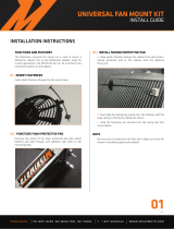
Torque Specifications
All fasteners must be torqued to specifications. Use manufacturers’ torque values
for OEM fasteners.
The torque values supplied in Table 1 are intended for VMAC supplied components,
or for use as a guide in the absence of a torque value provided by an OEM.
Torque values are with Loctite applied unless otherwise specified.
Table 1 — Torque Table
Standard Grade 8 National Coarse Thread
Size (in) 1/4 5/16 3/8 7/16 1/2 9/16 5/8 3/4
Foot pounds (ft•lb) 918 35 55 80 110 170 280
Newton meter (N•m) 12 24 47 74 108 149 230 379
Standard Grade 8 National Fine Thread
Size (in) 3/8 7/16 1/2 5/8 3/4
Foot pounds (ft•lb) 40 60 90 180 320
Newton meter (N•m) 54 81 122 244 434
Metric Class 10.9
Size (mm) M6 M8 M10 M12 M14 M16
Foot pounds (ft•lb) 4.5 19 41 69 104 174
Newton meter (N•m) 625 55 93 141 236
Apply Loctite 242 (blue) to all fasteners (except nylon lock nuts)
unless otherwise stated.

VMAC - Vehicle Mounted Air Compressors
VMAC Technical Support: 888-241-2289
VMAC Knowledge Base: kb.vmacair.com
8
Preparing for Installation
☐ Review the contents of the system using the illustrated parts list to ensure all
components are present and in the correct quantity. If any components are
missing, have the system ID ready and call VMAC Technical Support.
☐ Disconnect both batteries.
☐ Remove the driver side battery.
☐ Remove the lower bumper/air dam to improve access.
☐ Remove the top radiator cross member cover.
☐ Remove the fasteners securing the grille and pull gently to remove the grille
from the vehicle (there are (×2) fasteners located behind plastic covers on the
grille face).
☐ Remove the driver side headlight (there is (×1) fastener hidden behind the
rubber trim between the fender and the bumper).
☐ Drain the primary and secondary radiators into separate, clean containers. Set
the coolant aside for use later.
☐ Remove the upper radiator hose (primary cooling circuit) and set it aside.
☐ Disconnect the small diameter upper cooling circuit hoses from the primary
radiator and the primary degas bottle. Shift the hoses away from the front of
the engine compartment and secure them out of the way (Figure 1).
Figure 1 — Disconnect upper coolant circuit hoses
Disconnect upper
coolant circuit hoses
Preparation for installation is very important. Missing a step
or an item can cause problems in the installation or damage to
components.
☑
Check off each item as it is completed so that no steps are
missed.
When dissembling engine components, cover the openings to
prevent debris from entering the system.
Apply Loctite 242 (blue) to all fasteners (except nylon lock nuts)
unless otherwise stated.

VMAC - Vehicle Mounted Air Compressors
VMAC Technical Support: 888-241-2289
VMAC Knowledge Base: kb.vmacair.com
9
☐ Unclip the vacuum assembly from the back of the primary degas bottle
(Figure 4).
☐ Remove the intake air duct and set it aside.
☐ Disconnect the secondary cooling system hose running between the secondary
degas bottle and Charge Air Cooler (CAC) (Figure 2).
Figure 2 — Disconnect upper coolant circuit hoses
Disconnect upper
coolant circuit hoses
☐ Remove the secondary degas bottle (and hose) (Figure 3).
Figure 3 — Remove the secondary degas bottle
Figure 4 — Remove the vacuum assembly
Disconnect
hose
Unclip
assembly
Secondary
degas bottle

VMAC - Vehicle Mounted Air Compressors
VMAC Technical Support: 888-241-2289
VMAC Knowledge Base: kb.vmacair.com
10
☐ Disconnect the vacuum line and secure it out of the way (Figure 5).
☐ Disconnect the ‘hot’ side ducting from both the turbo and the CAC.
☐ Disconnect the “cold side” CAC ducting.
☐ Disconnect the remaining CAC connections.
☐ Remove the CAC and set it aside, along with the front bushing mount fasteners.
☐ Remove the driver side battery tray and degas bottle assembly. Retain the cap
from the degas bottle, it is the only part needed from this assembly.
☐ Remove the inner fender liner fasteners and pull the fender liner out of the way
to access the fasteners securing the washer fluid reservoir.
☐ Disconnect and remove the washer fluid reservoir and battery tray support
bracket; retain the fasteners (Figure 5).
☐ Drain the washer fluid into a clean receptacle and retain for use later.
☐ Set the fluid reservoir aside for use later.
☐ The battery tray support bracket will not be reused but can be retained should
the vehicle be reverted to stock.
☐ Remove and discard the cable run tray from the driver side battery cables
(Figure 6).
Retain
fasteners
Figure 5 — Retain fasteners
Remove cable
run tray
Figure 6 — Remove cable run tray

VMAC - Vehicle Mounted Air Compressors
VMAC Technical Support: 888-241-2289
VMAC Knowledge Base: kb.vmacair.com
11
☐ Remove the upper radiator shroud and set it aside, along with the fasteners.
☐ Disconnect the radiator fan harness and remove and discard the OEM bolt
(Figure 7).
Discard OEM
fastener
☐ Keeping the power steering lines connected, remove the power steering
reservoir from the driver side of the fan shroud.
☐ Temporarily tie the power steering reservoir up and out of the way of the
shroud.
Figure 7 — Disconnect fan harness
☐ Remove the fan and harness assembly.
☐ Remove the fan shroud stator.
☐ Remove the OEM FEAD belt.
☐ Take note of the location of the OEM idler on the power steering pump /
primary alternator bracket.
☐ Remove the OEM idler from the bracket (Figure 8).
Figure 8 — OEM alternator and power steering bracket
Remove
shroud post
Note location and
remove OEM idler
The power steering reservoir cap will leak if the reservoir is not kept
upright.

VMAC - Vehicle Mounted Air Compressors
VMAC Technical Support: 888-241-2289
VMAC Knowledge Base: kb.vmacair.com
12
☐ Remove the fan shroud stator post from the OEM bracket (Figure 8).
☐ Remove the primary alternator, setting the fasteners aside (Figure 8).
Figure 9 — Adaptive power steering pump
☐ Unbolt the power steering pump and secure it out of the way (retain the
fasteners).
Adaptive power
steering bushing
(OEM location)
Adaptive power
steering bushing
(VMAC location)
Figure 10 — Standard power steering pump (for comparison)
Do not remove the power steering fluid lines from the power
steering pump.
For vehicles equipped with the optional “Adaptive Power Steering”
power steering pump, relocate the upper rear bushing to the upper
forward mount position (Figure 9).
On vehicles equipped with adaptive power steering, removing the
power steering pump pulley will improve access to the fasteners.

VMAC - Vehicle Mounted Air Compressors
VMAC Technical Support: 888-241-2289
VMAC Knowledge Base: kb.vmacair.com
13
☐ Remove the OEM alternator / power steering pump bracket from the engine.
This will not be reused but may be retained.
☐ Remove the (×4) rubber bushings from the main bracket bolt holes and set
them, and the fasteners, aside for later.
☐ Remove the primary drain-back hose running between the engine and the OEM
degas bottle (Figure 11).
Figure 11 — Remove the primary drain-back hose
☐ Using the supplied 1/2 in loom, cover the section of harness (Figure 12).
☐ Using the supplied 1/4 in loom, cover the small sections of harness at the rear
of the engine (Figure 12).
Figure 12 — Remove the primary drain-back hose
Apply 1/2 in loom
Apply loom

VMAC - Vehicle Mounted Air Compressors
VMAC Technical Support: 888-241-2289
VMAC Knowledge Base: kb.vmacair.com
14
Relocating the ABS Hydraulic Control
Unit (HCU)
Failure to follow these instructions may result in brake system
contamination, component damage, and/or death.
If there is any concern that air may have entered the brake system,
consult a local Ford dealer or licensed repair facility for vehicle
specific HCU brake bleeding instructions.
Use extreme caution while adjusting the brake lines to prevent
damaging them.
If there is any concern that the brake lines may have been kinked or
damaged in any way, contact a local Ford dealer or licensed repair
facility to have the issues rectified.
Depending on the application, the following steps may not be
necessary. If the HCU is mounted towards the firewall
(Figure 19 on page 18), proceed to the next chapter. If the HCU
bracket is mounted using the holes shown in Figure 14, follow the
steps in this chapter.
Do not allow the brake master cylinder to run dry during these steps
as the master cylinder may be damaged if operated without fluid.
Use only clean brake fluid from an unopened container that meets
Ford specifications.
It may be necessary to rotate the brake lines that connect the
master cylinder to the ABS HCU module to avoid kinking the flexible
rubber hoses as the HCU is shifted to its new position. The following
process will help avoid air entering the brake system as brake fluid
will be forced out of the system rather than air permitted to enter
the system.
Do not pump the brakes at any time while the brake lines are loose
as air may be drawn into the system.
Have an assistant gently depress the service brake as the brake
line is loosened, rotated into a relaxed position and then quickly
retightened. Adjust one brake line at a time. If there is a significant
amount of brake fluid escaping from the fitting, the pedal is being
pressed too hard and/or the fitting has been loosened too much.

VMAC - Vehicle Mounted Air Compressors
VMAC Technical Support: 888-241-2289
VMAC Knowledge Base: kb.vmacair.com
15
Figure 13 — Steering assist module
Determine whether the vehicle is equipped electronic power assist steering (EPAS)
(Figure 13):*
☐ *If the vehicle is equipped with EPAS, turn to the next page.
☐ *If the vehicle is not equipped with the EPAS, skip to page 19.
Steering assist
module

VMAC - Vehicle Mounted Air Compressors
VMAC Technical Support: 888-241-2289
VMAC Knowledge Base: kb.vmacair.com
16
Figure 14 — Relocating the HCU
Vehicles equipped with EPAS
☐ Remove the (×2) nuts securing the HCU module to the bracket (Figure 14).
HCU nut
Figure 15 — Relocating the HCU
☐ Remove the bolt and (×2) nuts securing the HCU base bracket to the shock
tower and set them aside. Remove the HCU base bracket (Figure 15).
HCU nut

VMAC - Vehicle Mounted Air Compressors
VMAC Technical Support: 888-241-2289
VMAC Knowledge Base: kb.vmacair.com
17
☐ Mark and cut the HCU base bracket in the location shown (Figure 16).
Figure 16 — Modifying the HCU bracket
Mark and cut
HCU bracket
☐ Using the supplied flat head fastener, install the HCU relocation bracket
(Figure 17).
Figure 17 — Relocating the HCU
HCU relocation
bracket

VMAC - Vehicle Mounted Air Compressors
VMAC Technical Support: 888-241-2289
VMAC Knowledge Base: kb.vmacair.com
18
☐ Gently shift the HCU towards the firewall taking care not to bend or kink the
brake lines. Align the bracket with the second set of mounting holes (Figure 18).
☐ Using the OEM fasteners retained earlier, secure the HCU base bracket to the
shock tower (Figure 19).
Figure 18 — Relocating the HCU
Figure 19 — Relocating the HCU
Reinstall
both nuts
Reinstall
bolt
☐ Using the OEM fasteners retained earlier, secure the HCU module to the bracket.
/