Page is loading ...

C
e
r
t
i
f
i
e
d
C
o
m
p
a
n
y
ISO
ISO
9001
AO55AO55
Blind Analog TransmitterBlind Analog Transmitter
InstructionsInstructions
D
O
M
E
S
T
I
C
&
G
L
O
B
A
L
C
O
M
P
O
N
E
N
T
S

General Information
General Information ...................................................................................................................................................Page 3
Features ...........................................................................................................................................................................Page 3
Specications ................................................................................................................................................................Page 4
Dimensions ....................................................................................................................................................................Page 4
Installation and Setup
Mounting ........................................................................................................................................................................Page 5
Connection .....................................................................................................................................................................Page 5
Setting Frequency .......................................................................................................................................................Page 5
Setting Averaging Time .............................................................................................................................................Page 6
Checking Calibration ..................................................................................................................................................Page 6
Connection Diagrams
Wiring AO55 to a Mechanical Meter ...................................................................................................................Page 6
Wiring AO55 to a Magmeter...................................................................................................................................Page 7
Troubleshooting
Problems .........................................................................................................................................................................Page 7
Probable Causes ........................................................................................................................................................... Page 7
Things to Try ..................................................................................................................................................................Page 7
TABLE OF CONTENTS AO55 INSTRUCTIONS
Seametrics • 253.872.0284 Page 2 seametrics.com

GENERAL INFORMATION
The Seametrics AO55 is a blind (non-indicating) 4-20 mA
transmitter, designed for use with almost all Seametrics
ow sensors. It accepts a pulse frequency input from the
ow sensor, and converts this input into a continuous
analog output signal. Power for the transmitter is taken
from the current loop itself, so only two wires are required.
The digital design makes it possible to span the unit in
the eld without tools. The frequency at which 20 mA
is desired is entered on a set of rotary switches, and an
internal microcontroller automatically scales all other values
accordingly. An additional benet of the microcontroller is
its ability to average inputs, for smoothing of the output
signal. The degree of averaging can be selected in the eld,
from 2 to 16 seconds.
For maximum environmental protection, the electronic
components are encased in a special semi-exible urethane
potting material. The housing is cast from aluminum and
fuse-coated. The clamshell housing is connected directly
to the ow sensor or, in the wall mount version, provided
with mounting feet.
The AO55 will operate on a relatively wide range of current
loop voltages, 24 to 36 Vdc. Lower voltages limit the load
that can be applied to the loop without distortion of
the signal. (See Load/Supply chart if there is a question
regarding voltage vs. load.) A built-in power regulator
supplies the appropriate power to the ow sensor.
Typical applications for this transmitter are telemetry
(or SCADA), distributed control systems, programmable
controllers, data logging, and chart recording.
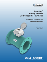
Features
4-20 mA adjustment switches
Averaging time switches
Loop power indicator light
Potted for moisture protection
Fusion coated cast aluminum housing
AO55 Wall Mount Shown
(meter mount also available)
Easy to use rotary switches for frequency setting
AO55 INSTRUCTIONS
Seametrics • 253.872.0284 Page 3 seametrics.com

AO55 INSTRUCTIONS
Seametrics • 253.872.0284 Page 4 seametrics.com
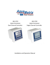
Specications *
Loop
Powe
r
(Vdc)
Load Resistance (Ohms)
400 600 800 1000
Load vs. Supply Voltage
Operating
Region
36
34
32
30
28
26
24
1200
*Specications subject to change.
Please consult our website for the most current data (www.seametrics.com).
Power 24–36 Vdc
Temperature 32˚ to 130˚ F (0˚ to 55˚ C )
Input Open collector solid state sensor
Input Averaging 2–16 seconds (switch selectable)
Response Time 2–60 seconds; 90% of full scale
(dependent on input averaging)
Frequency Minimum 10 Hz (@20mA)
Maximum 999.9 Hz
Setting 4 Rotary DIP switches
Output Proportional 4-20 mA
Environmental NEMA 4X, IP66
Dimensions
2.78" 3.93"
3.93"
1/2"
Female NPT
2.06"
4.52"
3.93"
2.57"
3.93"
AO55 (Wall Mount) AO55 (Meter Mount)
2.78" 3.93"
3.93"
1/2"
Female NPT
2.06"
4.52"
3.93"
2.57"
3.93"
GENERAL INFORMATION
When calculating total resistive load for loop power (volts/.020 amps = ohms)
be sure to subtract 800 Ω from the total to account for basic operation of the AO55

INSTALLATION AND SETUP
Mounting
The AO55M can be mounted on the ow sensor, or if wall
mounted comes with mounting feet and requires four
screws to attach it to any stable surface.
Connection
On either style of housing, the upper portion must be
removed to make connections. Use a standard hex wrench
(5/32” or 4 mm) to loosen the screws, then remove the
upper half. The connections are made to terminal blocks in
the upper half, which contains the potted electronics.
Consult the Connections diagram before connecting
to the current loop. The only connections required on
a meter mounted AO55 are the positive and negative
loop connections. If wall mounted, the sensor must also
be connected, since it is remote from the transmitter. Be
careful to follow the color coding of the ow sensor wires
in order to establish the correct polarity. Incorrect polarity
can damage the sensor.
Setting Frequency
The AO55 converts a train of o/on pulses from the ow
sensor into a continuous milliAmp signal that ranges from
4 mA at zero ow to 20 mA at the desired maximum ow.
The desired maximum is determined by the user and
entered as a frequency as follows:
1. Decide what ow rate should represent the top of
the scale. This is ordinarily the maximum expected
ow, or a value just above it, in gallons per minute.
2. Locate the K-factor of the ow sensor (found on
the meter or tting, or in the instruction manual,
depending on meter model). The K-factor is the
number of pulses the ow sensor produces per
gallon of ow.
3. Calculate frequency, using this formula:
K-Factor x Top Flow (GPM) = Frequency
60
4. Enter the frequency using the four rotary Frequency
switches. Note the decimal point between the third
and fourth switches.
Example for Setting Frequency
1. In an installation with an estimated maximum
ow rate of about 150 GPM, a ow rate of 170
GPM is selected as the full-scale maximum, the
ow at which the current loop will register 20
mA.
2. In this example, the K-factor (found on the
meter or tting, or in the manual) is “K =
54.50”.
3. Calculate the frequency as:
54.50 x 170 = 154.42
60
4. Rounding to one decimal point, enter 154.4 on
the rotary switches by turning the rotary switch
pointers to the desired digits.
0
9
8
7
6
5
4
3
2
1
0
9
8
7
6
5
4
3
2
1
0
9
8
7
6
5
4
3
2
1
0
9
8
7
6
5
4
3
2
1
Power
Sensor
4-20 mA
AO55
Frequency
1 5 4 .4
AO55 INSTRUCTIONS
Seametrics • 253.872.0284 Page 5 seametrics.com

SETUP AND CONNECTIONS
Setting Averaging Time
For most applications, this step can be ignored, as the
standard setting will work ne. However, when a particularly
steady output signal is desired, or in large pipe, a larger
averaging period may be desirable. Note however that
the averaging period requires a tradeoff, since a longer
averaging period implies a slower response time. If steady
signal is more important than fast response, increase the
averaging time as desired. See the diagram below for the
switch positions and their corresponding times.
0
9
8
7
6
5
4
3
2
1
0
9
8
7
6
5
4
3
2
1
0
9
8
7
6
5
4
3
2
1
0
9
8
7
6
5
4
3
2
1
AO55
Frequency
Power
Sensor
4-20 mA
UP
DOWN
LR
Switch Positions
Seconds L R
2 down down
4 down up
8 up down
16 up up
Checking Calibration
Normally it should not be necessary to check calibration,
since the digital design of this unit virtually eliminates drift.
However, there are two types of calibration check that can
be performed. Look at the diagram below to locate the 4
and 20 mA force switches. To force the 4 mA output, put
its switch in the up position. Check the current output at
the Power terminals, and if necessary trim to 4.00 mA using
the appropriate trimpot. Return the switch to the down
position, and repeat the process with the 20 mA switch.
0
9
8
7
6
5
4
3
2
1
0
9
8
7
6
5
4
3
2
1
0
9
8
7
6
5
4
3
2
1
0
9
8
7
6
5
4
3
2
1
AO55
Frequency
Power
Sensor
4-20 mA
4mA
Adjust
Force 4 mA
Force 20 mA
20 mA Adjust
S
Wiring AO55 to a Mechanical Meter
The AO55 can be wired to either a mechanical meter or a magmeter. See congurations below.
0
9
8
7
6
5
4
3
2
1
0
9
8
7
6
5
4
3
2
1
0
9
8
7
6
5
4
3
2
1
0
9
8
7
6
5
4
3
2
1
AO55
Frequency
Power
Sensor
4-20 mA
-
+
4-20 mA Device
(e.g. Pump, PLC,
Chart Recorder)
24-36 Vdc
Power Supply
(may be included in
control unit)
Mechanical
Sensor
Red
White
Black -
+
-
+
SBlack
Black
Red
AO55 INSTRUCTIONS
Seametrics • 253.872.0284 Page 6 seametrics.com

CONNECTIONS AND TROUBLESHOOTING
Wiring AO55 to an EX Magmeter
0
9
8
7
6
5
4
3
2
1
0
9
8
7
6
5
4
3
2
1
0
9
8
7
6
5
4
3
2
1
0
9
8
7
6
5
4
3
2
1
AO55
Frequency
Power
Sensor
4-20 mA
-
+
4-20 mA Device
(e.g. Pump, PLC
,
Chart Recorder)
24-36 Vdc
Power Supply
(may be included in
control unit)
-
+
S
+
+
+
+
_
_
_
_
Magmeter
Terminal Block
Power
Forward
Output
24 Vdc
-
+
Green
White
Black
Red
Black
Black
Red
Problem Probable Causes Things to try…
No analog signal at
reading device
Break in current loop Check if loop indicator light is on
Dead power supply Check multimeter voltage on power supply
Reversed polarity Check polarity
Output stuck at 4 mA No frequency input from ow sensor Check if ow sensor rotor is turning freely
(mechanical meters only)
Check ow sensor connections
Check ow sensor polarity
Be sure terminal blocks are rmly plugged in
With ow sensor disconnected, use short wire
to repeatedly short between sensor “sig” and
“–” terminals. Output should rise.
Verify 3-second pulse output (EX meters only)
mA signal does not
match ow rate
Inadequate voltage Check load vs. supply chart
Check multimeter voltage on power supply
Wrong frequency setting Review setting procedure
Troubleshooting
AO55 INSTRUCTIONS
Seametrics • 253.872.0284 Page 7 seametrics.com

LIMITED WARRANTY POLICY
The limited warranty set forth below is given by Seametrics, with respect to Seametrics brand products purchased in the United States of America.
Seametrics warrants that products manufactured by Seametrics, when delivered to you in new condition in their original containers
and properly installed, shall be free from defects in material and workmanship. Seametrics products are warranted against defects
for a minimum period of two (2) years from date of installation, unless otherwise specied, with proof of install date. If no
proof of install date can be provided, warranty period will be two (2) years from date of shipment from Seametrics, as dened
on Seametrics’ invoice. Seametrics’ obligation under this warranty shall be limited to replacing or repairing the part or parts, or, at
Seametrics’ option, the products, which prove defective in material or workmanship. The following are the terms of Seametrics’ limited
warranty:
a. Buyer must give Seametrics prompt notice of any defect or failure and satisfactory proof thereof.
b. Any defective part or parts must be returned to Seametrics’ factory or to an authorized service center for inspection.
c. Buyer will prepay all freight charges to return any products to Seametrics’ factory, or another repair facility. as designated by
Seametrics.
d. Defective products, or parts thereof, which are returned to Seametrics and proved to be defective upon inspection, will be repaired
to factory specications.
e. Seametrics will deliver repaired products or replacements for defective products to the buyer (ground freight prepaid) to the
destination provided in the original order.
f. Products returned to Seametrics for which Seametrics provides replacement under this warranty shall become the property of
Seametrics.
g. This limited warranty covers all defects encountered in normal use of Seametrics products, and does not apply to the following
cases:
i. Loss of or damage to Seametrics product due to abuse, mishandling, or improper packaging by buyer
ii. Failure to follow operating, maintenance, or environmental instructions prescribed in Seametrics’ instruction manual
iii. Products not used for their intended purpose
iv. Alterations to the product, purposeful or accidental
v. Electrical current uctuations
vi. Corrosion due to aggressive materials not approved for your specic product
vii. Mishandling, or misapplication of Seametrics products
viii. Products or parts that are typically consumed during normal operation
ix. Use of parts or supplies (other than those sold by Seametrics) which cause damage to the products, or cause abnormally
frequent service calls or service problems
h. A new warranty period will be established for repaired products, or products replaced during the original warranty period.
i. In the event that equipment is altered or repaired by the buyer without prior written approval by Seametrics, all warranties are void.
Damage caused by equipment or accessories not manufactured by Seametrics may void the product’s warranty.
j. SOFTWARE: The Seller grants the user a non-exclusive license to use Seametrics’ software, according to the following limitations
and conditions:
i. The user may install the software on one or more desktop or laptop computers.
ii. All title and intellectual rights to the software are owned by Seametrics.
iii. No copies may be made or distributed except as described above.
iv. The user may not modify or reverse-engineer the software.
THE FOREGOING WARRANTY IS IN LIEU OF ALL OTHER WARRANTIES, WHETHER ORAL, WRITTEN, EXPRESSED, IMPLIED OR STATUTORY.
NO IMPLIED WARRANTY, INCLUDING ANY IMPLIED WARRANTY OF MERCHANTABILITY OR FITNESS FOR A PARTICULAR PURPOSE,
APPLIED TO THE PRODUCTS AFTER THE APPLICABLE PERIOD OF THE EXPRESS LIMITED WARRANTY STATED ABOVE, AND NO OTHER
EXPRESS WARRANTY OR GUARANTY, EXCEPT AS MENTIONED ABOVE, GIVEN BY ANY PERSON OR ENTITY WITH RESPECT TO THE
PRODUCTS, SHALL BIND SEAMETRICS. SEAMETRICS SHALL NOT BE LIABLE FOR LOSS OF REVENUES, OR PROFITS, OR INCONVENIENCES,
EXPENSE FOR SUBSTITUTE EQUIPMENT OR SERVICE, STORAGE CHARGES, LOSS OF DATA, OR ANY OTHER SPECIAL, INCIDENTAL, OR
CONSEQUENTIAL DAMAGE CAUSED BY THE USE OR MISUSE OF, OR INABILITY TO USE THE PRODUCTS, REGARDLESS OF THE LEGAL
THEORY ON WHICH THE CLAIM IS BASED, AND EVEN IF SEAMETRICS HAS BEEN ADVISED OF THE POSSIBILITY OF SUCH DAMAGES. IN NO
EVENT SHALL RECOVERY OF ANY KIND AGAINST SEAMETRICS BE GREATER IN AMOUNT THAN THE PURCHASE PRICE OF THE PRODUCT
SOLD BY SEAMETRICS AND CAUSING THE ALLEGED DAMAGE. WITHOUT LIMITING THE FOREGOING, YOU ASSUME ALL RISK OF LIABILITY
FOR LOSS, DAMAGE, OR INJURY TO YOU AND YOUR PROPERTY AND TO OTHERS AND THEIR PROPERTY ARISING OUT OF USE OR MISUSE
OF, OR INABILITY TO USE THE PRODUCTS NOT CAUSED DIRECTLY BY THE NEGLIGENCE OF SEAMETRICS.
SOME STATES DO NOT ALLOW LIMITATIONS ON THE DURATION OF AN IMPLIED WARRANTY, SO THE ABOVE LIMITATIONS MAY NOT
APPLY TO YOU. SIMILARLY, SOME STATES DO NOT ALLOW THE EXCLUSION OR LIMITATIONS OF CONSEQUENTIAL DAMAGE, SO THE
ABOVE LIMITATION OR EXCLUSION MAY NOT APPLY TO YOU. THIS LIMITED WARRANTY GIVES YOU SPECIFIC LEGAL RIGHTS; HOWEVER,
YOU MAY ALSO HAVE OTHER RIGHTS WHICH MAY VARY FROM STATE TO STATE.
Seametrics • 19026 72nd Avenue South • Kent, Washington 98032 • USA
(P) 253.872.0284 • (F) 253.872.0285 • 1.800.975.8153 • seametrics.com LT-65200015r3-20190218
2/18/2019
AO55 INSTRUCTIONS
/