Page is loading ...

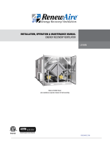
INSTALLATION, OPERATION & MAINTENANCE MANUAL
ENERGY RECOVERY VENTILATOR
RENEWAIRE.COM
LE6XRT
Model LE6XRTH Shown
(also available as separate modules for field assembly)

LE6XRT ERV
RENEWAIRE.COM INSTALLATION, OPERATION AND MAINTENANCE MANUAL 1.800.627.44992
IMPORTANT SAFETY INFORMATION
This unit is intended for general ventilating only. Do not use to
exhaust hazardous or explosive materials and vapors. Do not
connect this equipment to range hoods, fume hoods or collection
systems for toxics.
This unit is for ventilating finished structures only. It is not to
be used until after all construction has been completed and
construction debris and dust are cleaned from the Occupied
Space.
This equipment is to be installed by following Industry Best
Practices and all applicable codes. Any damage to components,
assemblies, subassemblies or the cabinet which is caused by
improper installation practices will void the warranty.
NOTICENOTICE
NOTICE
WARNING
ARC FLASH AND ELECTRIC SHOCK HAZARD
Arc flash and electric shock hazard. Disconnect all electric
power supplies, verify with a voltmeter that electric power is off
and wear protective equipment per NFPA 70E before working
within electric control enclosure. Failure to comply can cause
serious injury or death.
Customer must provide earth ground to unit, per NEC, CEC and
local codes, as applicable.
Before proceeding with installation, read all instructions,
verifying that all the parts are included and check the nameplate
to be sure the voltage matches available utility power.
The line side of the disconnect switch contains live high-voltage.
The only way to ensure that there is NO voltage inside the unit
is to install and open a remote disconnect switch and verify that
power is off with a volt meter. Refer to unit electrical schematic.
Follow all local codes.
RISK OF ELECTRIC SHOCK OR EQUIPMENT DAMAGE
Whenever electrical wiring is connected, disconnected or
changed, the power supply to the ERV and its controls must
be disconnected. Lock and tag the disconnect switch or circuit
breaker to prevent accidental reconnection of electric power.
RISK OF CONTACT WITH HIGH SPEED MOVING PARTS.
Disconnect all local and remote power supplies, verify with
a voltmeter that electric power is off and all fan blades have
stopped rotating before working on the unit.
Do not operate this unit with any cabinet panels removed or
prior to assembly of the modules
RISK OF DAMAGE TO ENTHALPIC CORES
Whenever working within the ERV cabinet, protect the enthalpic
cores from accidental damage. The core media is subject to
damage from dropped tools or other foreign objects.
RISK OF CONTACT WITH HOT SURFACES
The blower motor and other electrical components are extremely
hot during operation. Allow sufficient time for them to cool
before working within the unit cabinet. Use extreme caution and
wear protective gloves and arm protection when working on or
near hot blower motors and electrical components.
CAUTION CAUTION
CAUTION
CAUTION

LE6XRT ERV
3 1.800.627.4499 INSTALLATION, OPERATION AND MAINTENANCE MANUAL RENEWAIRE.COM
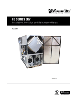
In the unlikely event that factory assistance is ever required, information located on the unit label will
be needed.
UNIT INFORMATION
IMPORTANT USER INFORMATION
IMPORTANT
IMPORTANT
IMPORTANT
This manual contains space for maintaining written records of unit maintenance and / or repairs.
See Section 11.9, Maintenance Records. At the time the ERV is commissioned, a maintenance
schedule should be developed by the user to incorporate monthly and seasonal maintenance and
include start-up maintenance tasks as described in this manual.
If this unit is installed in an area where it may draw air from a nearby fuel-burning device such as
a gas furnace or water heater, verify that the air being extracted by the ERV does not conflict with
proper operation of the fuel-burning device.
This unit can be delivered in two modules for on-site assembly or as a completely assembled unit
(additional charges apply).
See separate SHIPPING & RIGGING manual for information on shipping considerations, rigging,
moving and lifting the unit as separate modules or as a complete unit.
Configuration (Option) Code
Unit Label (typical)
READ AND SAVE THIS MANUAL/LIRE ET CONSERVER CE MANUEL

LE6XRT ERV
RENEWAIRE.COM INSTALLATION, OPERATION AND MAINTENANCE MANUAL 1.800.627.44994
TABLE OF CONTENTS
IMPORTANT SAFETY INFORMATION 2
UNIT INFORMATION 3
CONFIGURATION CODE FOR LE6XRT MODELS 6
LE6XRT SUBMITTAL SPECIFICATIONS 7
LE6XRT RTV/RTR DIMENSIONS 8
LE6XRT RTH/RTF DIMENSIONS 9
1.0 OVERVIEW 10
1.1 DESCRIPTION 10
1.2 FACTORY ASSEMBLY OF MODULES 10
1.3 MODELS 10
1.3.1 LE6XRTF 10
1.3.2 LE6XRTH 10
1.3.3 LE6XRTR 11
1.3.3 LE6XRTV 11
1.4 CURBS 11
2.0 COMPONENT DESCRIPTION 12
2.1 CABINET CONSTRUCTION 12
2.1.1 Cabinet Paint 12
2.1.2 Hoods 12
2.2 FAN MOTORS 12
2.3 FAN SPEED CONTROL 12
2.4 DAMPERS 12
2.5 ENTHALPIC CORE 12
2.6 FILTERS 12
2.6.1 Filter Monitors 12
2.7 CONTROLS 13
2.7.1 Integrated Microprocessor Controls 13
2.7.2 Variable Frequency Drive 14
2.8 OPTIONAL CONTROL ACCESSORIES 14
2.8.1 Carbon Dioxide Control 14
2.8.2 Digital Time Clock 14
2.8.3 Indoor Air Quality Sensor (IAQ) 15
2.8.4 Motion Occupancy Control 15
2.8.5 Smoke Detector 15
3.0 UNIT WEIGHTS 16
3.1 LE6XRT CORNER WEIGHTS 16
4.0 SHIPPING / RECEIVING / HANDLING 17
4.1 UNIT WEIGHTS / DIMENSIONS 17
4.1.1 Unit Dimensions and Weight 17
4.1.2 Shipping Dimensions and Weight 17
4.2 RECEIVING 17
4.3 RIGGING 17
4.4 HANDLING AND STORAGE 17
5.0 UNIT PLACEMENT 18
5.1 SOUND ATTENUATION OUTSIDE THE BUILDING 18
5.2 PLACEMENT CAUTIONS 18
5.3 SERVICE CLEARANCES 18
6.0 INSTALLATION 19
6.1 ASSEMBLY OF MODULES 19
6.2 DUCT CONNECTIONS 19
6.3 INDOOR SOUND ATTENUATION 19
6.4 ELECTRICAL CONNECTIONS 20
6.4.1 Factory-Recommended Electric Service Entry 20
6.5 WIRING SCHEMATICS 21
6.6 CONTROL CONNECTIONS 23
7.0 CONTROL CONTRACTOR INFORMATION 23
7.1 24 VAC CLASS II POWER SUPPLY 23
7.2 MOTOR PROTECTION 24
7.2.1 Units Equipped with Motor Starters 24
7.2.2 Units With Variable Frequency Drives (VFDs) 25
7.3 EXTERNAL CONTROL CONNECTIONS 25
7.3.1 Single 2 - Wire Control, Unpowered 25
7.3.2 Single 2 - Wire Control, Separate Power 26
7.3.3 Control Sending 24 VAC “ON” Signal 26
7.3.4 External Control Using ERV Power Supply 26
7.3.5 Control with 2 Non-Powered Relay Contacts 26
7.3.6 Control with 2 “ON” Signals, External Power 27
7.4 SEQUENCE OF OPERATION 27
8.0 PRE START-UP 29
8.1 VERIFY VOLTAGES 29
8.2 VERIFY TRANSFORMER WIRING 29
8.3 INSPECT FILTERS 29
8.4 INSPECT FOAM GASKETING 29
8.5 INSPECT MOTOR VIBRATION ISOLATORS 29
8.6 INSPECT BELTS AND VERIFY SHEAVE ALIGNMENT 29
8.7 INSPECT FAN 29
8.8 INSPECT AND CLEAN THE INTERIOR 29
8.9 INSPECT DUCTWORK CONNECTIONS 29
9.0 START-UP 30
9.1 VERIFY CORRECT FAN ROTATION DIRECTION 30
9.2 BASIC OPERATIONAL CHECK 30
9.2.1 Motor Starter Units 30
9.2.2 VFD Units 30
9.3 ADJUST MOTOR SHEAVES 31
10.0 MAINTENANCE 31
10.1 MAINTENANCE 24 HRS. AFTER START-UP 31
10.2 MAINTENANCE 30 DAYS AFTER START-UP 31
10.3 MAINTENANCE SCHEDULE 31
10.4 FILTERS 31
10.5 ELECTRIC MOTOR MAINTENANCE 32
10.5.1 Belt Tension 32
10.5.2 Sheave Condition 32
10.5.3 Motor Cleanliness 32
10.5.4 Motor Lubrication 32
10.6 PILLOW BLOCKS 35
10.7 ENTHALPIC CORE MAINTENANCE 36
10.7.1 Removal of Enthalpic Cores 36
10.7.2 Reinstallation of Enthalpic Cores 36
10.8 SERVICE PARTS 37
11.0 MAINTENANCE REFERENCE 38
11.1 PLENUM DIVIDERS 38
11.2 FAN / MOTOR REMOVAL 38
11.3 VIBRATION ISOLATOR ADJUSTMENT 38
11.4 RISK OF CORE DAMAGE 39
11.5 FILTER REPLACEMENT PRACTICES 39

LE6XRT ERV
5 1.800.627.4499 INSTALLATION, OPERATION AND MAINTENANCE MANUAL RENEWAIRE.COM
TABLE OF CONTENTS (cont’d)
TABLE OF ILLUSTRATIONS
Unit Label (typical) 3
LE6XRT SUBMITTAL SPECIFICATIONS 7
LE6XRT RTV/RTR DIMENSIONS 8
LE6XRT RTH/RTF DIMENSIONS 9
LE6XRTF Duct Configuration 10
LE6XRTH Duct Configuration 10
LE6XRTR Duct Configuration 11
LE6XRTV Duct Configuration 11
LE6XRT Hood (typ) 11
LE6XRT Hood Shipping Location (typ) 11
RenewAire Microprocessor Controller 13
Premium Microprocessor Controls Installed 13
RenewAire Microprocessor Controller Expansion Board 13
Carbon Dioxide Sensor, Room/Wall Mount 14
Time Clock, Panel Mount 14
VFDs Mounted Inside ERV 14
Time Clock, Exterior Enclosure 14
Carbon Dioxide Sensor, Duct Mount 14
VFD Keypads Found in E-Box 14
Time Clock, Exterior 14
IAQ Sensor, Wall Mount 15
Ceiling Mount Occupancy Sensor 15
Smoke Detector 15
IAQ Sensor, Duct Mount 15
Wall Mount Occupancy Sensor 15
LE6XRT Corner Weights 16
Double-Flange Duct Connection 19
E-Box Main Disconnect Switch 20
E-Box with Knockouts on Bottom 20
E-Box Low Voltage Terminal Strip 20
24 VAC Power Supply Transformer 23
Dry Contactors and Overload Relays 25
Clean Filter Pressure Drop Table (in. w.g.) 31
Fan Belt Tensioning 32
Fan Pillow Block 35
End View of Core Support Assembly 36
LE6XRT Service Parts 37
Fan and Motor Sled 38
Plenum Divider Panels 38
Filter Extractor Hook 39
Typical Spring-Type Vibration Isolator 39
Filter Spacers 39
Air Flow Test Port 40
Door Latch Adjustment 40
Air Flow Test Port Location 40
Table of Sheave Adjustments 41
Two-Belt Adjustable Sheave (typ) 41
TABLE OF WIRING SCHEMATICS
Single Phase Wiring Schematic 21
Three Phase Wiring Schematic 22
Single 2-Wire Control, Unpowered 25
24 VAC From External Source 26
External Control Using ERV 24 VAC 26
Control with 2 Non-Powered Relay Contacts 27
Control with 2 “ON” Signals, External Power 27
11.6 DOOR LATCH ADJUSTMENT 40
11.7 MEASURING AIRFLOW 40
11.8 SHEAVE ADJUSTMENT 41
11.9 MAINTENANCE RECORDS 42

LE6XRT ERV
RENEWAIRE.COM INSTALLATION, OPERATION AND MAINTENANCE MANUAL 1.800.627.44996
CONFIGURATION CODE FOR LE6XRT MODELS
LE MODELS
CONFIGURATION GUIDE
Note: Not all options are available on every model.
For Technical Support E-mail: [email protected]
To Place an Order E-mail: [email protected]
MODEL NUMBER
L E J - -
DIGIT NUMBER 1 2 3 4 5 6 7 8 9 10 11 12 13 14 15 16 17 18 19 20 21 22 23 24 25
Digits 1–5: Model Digit 18: Flow Control
"LE-6X" "-" = No Isolation Damper
"LE-8X" "D" = Motorized Damper both Airstreams
"LE10X" "E" = Motorized Damper EA or RA Airstream
"F" = Motorized Damper FA or OA Airstream
Digits 7–8: Location
"IN" = Indoor Digit 19: Unit Control (see Restrictions 6 & 7)
"RT" = Rooftop "A" = Standard Unit Control Wiring
"V" = Onboard VFD Both Airstreams
Digit 9: Orientation
"V", "H" (Indoor Units) Digit 20: Disconnect
"V", "H", "R", "F" (Rooftop Units) "N" = Non-Fused (Standard)
"F" = Fused
Digit 10: Vibration Isolation
"N" = Neoprene Isolators Digit 21: Unit Control Enhancements
"S" = Spring Isolators "T" = Transformer with Isolation Relay (Standard)
"1" = Enhanced Controls
Digit 11: Wall Type "2" = Premium Controls
"S" = Single "3" = Enhanced Controls with BACnet License
"D" = Double "4" = Premium Controls with BACnet License
Digit 12: Phase (See Restriction 2) Digit 22: Filter Options (see Restriction 8)
"1" = Single Phase "-" = None (Standard)
"3" = Three Phase "F" = Filter Monitor Both Airstreams
Digit 13: Voltage (see Restriction 1) Digit 23: Flexible Packaging
"4" = 460V "A" = Assembled (single piece flat bed)
"5" = 208–230V "M" = Modular (two pieces for enclosed trailer)
"8" = 575V
Digit 24: Paint and Customization
Digit 14: FA Horsepower (see Restrictions 2, 3 & 4) "-" = None
"D" = 3 HP Low Speed "W" = White Paint
"F" = 3 HP Medium Speed "C" = Custom Paint
"G" = 3 HP High Speed "X" = Custom Unit
"J" = 5 HP Low Speed
"K" = 5 HP Medium Speed Digit 25: Safety Listing (see Restriction 5)
"L" = 5 HP High Speed "L" = Listed
"M" = 7.5 HP Low Speed "N" = Non-Listed
"N" = 7.5 HP Medium Speed
"P" = 7.5 HP High Speed
"Q" = 10 HP Medium Speed
"R" = 10 HP High Speed
Digit 15: EA Horsepower (see Restrictions 2, 3 & 4)
"D" = 3 HP Low Speed
"F" = 3 HP Medium Speed
"G" = 3 HP High Speed
"J" = 5 HP Low Speed
"K" = 5 HP Medium Speed
"L" = 5 HP High Speed
"M" = 7.5 HP Low Speed
"N" = 7.5 HP Medium Speed
"P" = 7.5 HP High Speed
"Q" = 10 HP Medium Speed
"R" = 10 HP High Speed
*NOTES:
Digit 6 "J" = G5 Core Type. Digits 16 and 17 are not used in these models.
NOTE: When the Configuration
Code is printed on the unit
label, it is identified as the
“Option Code”. See illustration
on Page 3.
LE MODELS
CONFIGURATION GUIDE
Note: Not all options are available on every model.
For Technical Support E-mail: [email protected]
To Place an Order E-mail: [email protected]
MODEL NUMBER
L E J - -
DIGIT NUMBER 1 2 3 4 5 6 7 8 9 10 11 12 13 14 15 16 17 18 19 20 21 22 23 24 25
Restrictions:
1: Voltage Codes "4" & "8" only available with Phase Code "3" (Three-Phase).
2: Phase Code "1" only available in Motor Codes "D", "F", & "G".
3: Motor Code "P" (7.5 HP High Speed) not available in LE-6X.
4: Motor Codes "Q" and "R" (all 10 HP Speeds) not available in LE-6X & LE-8X.
5: Some units with Customization Code "X" are not safety listed.
6: Unit Control Code "V" only available with Motor Codes "G", "L", & "N" in LE-6X.
7: Unit Control Code "V" only available with Motor Codes "G", "L", "P", & "R" in LE-8X & LE10X.
8: Filter Code "F" not available with Unit Control Enhancements Codes "1", "2", "3", & "4". Filter Monitor is provided with those options.

7 1.800.627.4499 INSTALLATION, OPERATION AND MAINTENANCE MANUAL RENEWAIRE.COM
Subject to change without notice: RENEWAIRE.COM | 1.800.627.4499
98 Subject to change without notice: RENEWAIRE.COM | 1.800.627.4499
SPECIFICATIONS & DIMENSIONS
ELECTRICAL DATA
Standard Electrical Specifications Optional Factory Installed
VFD Electrical Specifications
HP Volts HZ Phase FLA
per motor
Min. Cir.
Amps
Max.
Overcurrent
Protection
Device
FLA
per motor
Min. Cir.
Amps
Max.
Overcurrent
Protection
Device
3.0 208-230 60 Single 14.7-14 33.1 40 9.38-8.48 40.2 45
3.0
208-230
460
575
60
60
60
Three
Three
Three
9.38-8.48
4.24
3.3
21.1
9.5
7.4
25
15
15
9.38-8.48
4.24
3.3
23.2
10.5
8.2
25
15
15
5.0
208-230
460
575
60
60
60
Three
Three
Three
14.5-13.4
6.7
5.3
32.6
15.1
11.9
45
20
15
14.5-13.4
6.7
5.3
35.9
16.6
13.1
45
20
15
7.5
208-230
460
575
60
60
60
Three
Three
Three
21.0-19.0
9.5
7.6
47.3
21.4
17.1
60
25
20
21.0-19.0
9.5
7.6
52.0
23.5
18.8
60
25
20
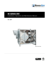
Energy Recovery Ventilator
Standard
6XRT
HE
LE
SPECIFICATIONS
Ventilation Type:
Static plate, heat and humidity transfer
Typical Airflow Range: 1,500-6,600 CFM
AHRI 1060 Certified Core: Six L125-G5
Standard Features:
TEFC Premium efficiency motors
Motor starters
Non-fused disconnect
24 VAC transformer/relay package
Cross-core differential pressure ports
Filters:
Total qty. 12, MERV 8: 20" x 25" x 2"
Unit Weight:
Modular (per module) 1,069-1,461 lbs., varies by option(s)
Assembled (1-piece) 2,086-2,753 lbs., varies by option(s)
Max. Shipping Dimensions & Weight (on pallet):
Modular (2-modules) 80" L x 90" W x 78" H
Module 1 - 1,602 lbs., Module 2 - 1,491 lbs.
Assembled (1-piece) 160" L x 90" W x 78" H -
3,035 lbs.
Motor(s):
Qty. 2, Belt drive blower/standard motor packages
with choice of adjustable sheaves for low,
medium or high blower speed (see table below)
Options:
Spring vibration isolators
Onboard variable frequency drives (VFDs) -
both airstreams
Shaft grounding ring on motors with VFDs
Fused disconnect
Integrated programmable controls -
enhanced, premium
Class 1 low leakage motorized isolation dampers -
OA, RA or both airstreams
Qty. 2, Factory mounted filter alarms -
both airstreams
Double wall construction
Exterior paint - white, custom colors
Accessories:
Filters - MERV 13, 2" or 4"; MERV 8, 4" (shipped loose)
Automatic balancing damper - 4", 5", 6"
Roof curb - standard 14"
Curb wind clip
Engineered combo curb for Carrier RTU
Engineered combo curb for Trane RTU
Digital time clock - wall mount (TC7D-W),
in exterior enclosure (TC7D-E)
Carbon dioxide sensor/control -
wall mount (CO2-W), duct mount (CO2-D)
IAQ sensor - wall mount (IAQ-W),
duct mount (IAQ-D)
Motion occupancy sensor/control -
ceiling mount (MC-C), wall mount (MC-W)
Smoke Detector - duct mount (SD-D)
Electric duct heater - EK series (1–175 kW);
designed for indoor ductwork installation only
Indirect gas-fired duct furnace - GH series
(50-400 MBH), installed downstream of any fans
AIRFLOW PERFORMANCE
Airflow
CFM
External Static Pressure (in.w.g.)
0.00 0.25 0.50 0.75 1.00 1.25 1.50 1.75 2.00
BHP RPM BHP RPM BHP RPM BHP RPM BHP RPM BHP RPM BHP RPM BHP RPM BHP RPM
3 HP LOW SPEED
3 HP MED SPEED 3 HP HIGH SPEED
1500 0.9 840 1.1 920 1.5 990 1.9 1060 2.4 1120
2000 0.9 770 1.1 860 1.4 940 1.7 1010 2.2 1080 2.6 1140
2500 1.1 800 1.3 880 1.7 950 2.0 1030 2.4 1090 2.9 1150
3000 1.4 830 1.7 900 2.0 970 2.3 1040 2.7 1110 3.1 1170 5 HP MED
3500 1.6 800 1.8 870 2.1 930 2.4 1000 2.7 1060 3.1 1120 3.5 1190
5 HP HIGH
SPEED
3750 1.6 760 1.8 820 2.0 890 2.3 950 2.6 1010 2.9 1070 3.3 1130 3.7 1190
4000 1.8 790 2.0 850 2.3 910 2.5 970 2.8 1030 3.2 1090 3.5 1150 3.9 1200
4250 3 HP
LOW
SPEED
1.9 770 2.1 820 2.3 880 2.5 930 2.8 990 3.1 1040 3.4 1100 3.7 1160 4.1 1210
4500 2.2 800 2.4 850 2.6 900 2.8 960 3.1 1010 3.4 1060 3.7 1110 4.0 1170 4.3 1230
4750 2.5 840 2.7 880 2.9 930 3.1 980 3.4 1030 3.7 1080 4.0 1130 4.3 1180 4.6 1240
5000 2.8 870 3.0 910 3.2 960 3.5 1000 3.7 1050 4.0 1100 4.3 1150 4.6 1200 4.9 1250
5250
5 HP
LOW
SPEED
3.2 910 3.4 940 3.6 990 3.8 1030 4.1 1070 4.3 1120 4.6 1170 4.9 1220 5.3 1270
5500 3.6 940 3.8 970 4.0 1010 4.2 1050 4.5 1090 4.7 1140 5.0 1180 5.3 1230 5.6 1290
5750 4.0 970 4.2 1000 4.4 1040 4.6 1080 4.9 1120 5.1 1160 5.4 1200 5.7 1250 6.0 1300
6000 4.4 1000 4.6 1030 4.8 1070 5.0 1100 5.3 1140 5.5 1180 5.8 1230 6.1 1270 6.4 1330
6250 4.9 1030 5.1 1060 5.3 1090 5.5 1130 5.7 1160 6.0 1200 6.2 1250 6.5 1300 6.9 1350
6500 5.3 1060 5.5 1090 5.7 1120 6.0 1150 6.2 1190 6.4 1230 6.7 1270 7.0 1320 7.4 1380
6600 5.5 1070 5.7 1100 5.9 1130 6.1 1160 6.4 1200 6.6 1240 6.9 1280 7.2 1330 7.5 1390
7.5 HP LOW SPEED 7.5 HP MED SPEED
Note: Airflow performance includes effect of clean, standard filter supplied with unit.
ROOFTOP UNIT
LE10XRT shown
Energy Recovery Core is AHRI Certified®

RENEWAIRE.COM INSTALLATION, OPERATION AND MAINTENANCE MANUAL 1.800.627.44998
Subject to change without notice: RENEWAIRE.COM | 1.800.627.4499 98 Subject to change without notice: RENEWAIRE.COM | 1.800.627.4499
SPECIFICATIONS & DIMENSIONS
2" Duct
Flange Typ.
73 3/8"
Lifting Lugs
19 5/8"
Typ.
22 1/4"
69 1/4" Case
111 1/8" Overall
2" Typ.
FRONT VIEW
Pressure Ports
(4) Typ.
FA
RTR
ONLY
FA
RTV
ONLY
RA
122 5/8" Case
125 3/8" Overall
OA Inlets,
OA Damper
Locations
(Optional)
RIGHT VIEW
53 1/2"
44 5/8"
8 7/8"
25 1/4"
4"
65 5/8" Case
71 1/8" Overall
C
L
11 3/8"
(5)
7/8"
Knockouts
C
L
5 1/4"
(2)
7/8"
Knockouts
Disconnect
Switch
E-Box
EA Outlet
13 3/8" X 15 1/2"
Electrical
Connection
Cover
FA (RTR)
32" X 24"
Duct Receiving
Flange
18 3/8"
49 5/8"
41"
46"
36" E-Box
Minimum
Service Area
111" Minimum
Service Area
60 1/4"
Minimum
Blower Service
Area Typ.
69 3/4" Minimum
Service Area
TOP VIEW
Door
Swing
Door
Swing
Door
Swing
Door
Swing
OA
OA
EA
FA (RTV)
16 1/8" X 19 1/2"
Opening
RA
24" X 32"
Opening
RA Damper
Location
(Optional)
115 1/4" O.D.
64 1/4" O.D.
3"
60 1/2" I.D.
17 1/4"
33"
20" 25"
9 1/2"
A
A
TOP VIEW
CURB LE6X
FA
RA
1 7/8"
3"
14"
SECTION
A-A
CURB CROSS-SECTION
A-A (TYP.)
1 1/2" X 1/4"
Neoprene Gasket
3/4" X 3 1/2"
Wooden Nailer
LEFT VIEW
Model: LE6X RTV/RTR
Drawing Type: Unit Dimension
Version: MAY18
ABBREVIATIONS
EA: Exhaust Air to outside
OA: Outside Air intake
RA: Room Air to be exhausted
FA: Fresh Air to inside
RTV: Rooftop Vertical RA & FA
RTR: Rooftop Vertical RA Only
INSTALLATION ORIENTATION
Unit must be installed in orientation
shown.
NOTE:
1. UNLESS OTHERWISE SPECIFIED,
DIMENSIONS ARE ROUNDED TO THE
NEAREST EIGHTH OF AN INCH.
2. SPECIFICATIONS MAY BE SUBJECT
TO CHANGE WITHOUT NOTICE.
LE6XRT (RTV/RTR) Energy Recovery Ventilator Standard
AIRFLOW ORIENTATION
Available as shown:
UNIT MOUNTING & APPLICATION
Must be mounted as shown. Airstreams can not
be switched.
EA
AR
AF
OA
HERT except 6x 8x, LERT
RTV
AR
FA
EA OA
HERT except 6x 8x, LERT
RTR

9 1.800.627.4499 INSTALLATION, OPERATION AND MAINTENANCE MANUAL RENEWAIRE.COM
Subject to change without notice: RENEWAIRE.COM | 1.800.627.4499 1110 Subject to change without notice: RENEWAIRE.COM | 1.800.627.4499
SPECIFICATIONS & DIMENSIONS
2" Typ.
2" Duct
Flange Typ.
73 3/8"
Lifting Lugs
19 5/8"
Typ.
22 1/4"
69 1/4" Case
111 1/8" Overall
5" Damper
Frames Typ.
FRONT VIEW
Pressure Ports
(4) Typ.
FA
RTH
ONLY
RA
FA
RTF
ONLY
122 5/8" Case
125 3/8" Overall
25 3/8"
8 3/4"
OA Inlets,
OA Damper
Locations
(Optional)
RIGHT VIEW
RA
32" X 24"
Duct Receiving
Flange
RA Damper
Location
(Optional)
53 1/2"
44 5/8"
8 3/4"
25 1/4"
4"
65 5/8" Case
71 1/8" Overall
C
L
5 1/4"
(2)
7/8"
Knockouts
C
L
11 3/8"
(5)
7/8"
Knockouts
Disconnect
Switch
E-Box
EA Outlet
13 3/8" X 15 1/2"
Electrical
Connection
Cover
FA (RTH)
32" X 24"
Duct Receiving
Flange
18 3/8"
46"
36" E-Box
Minimum
Service Area
111" Minimum
Service Area
60 1/4"
Minimum
Blower Service
Area Typ.
69 3/4" Minimum
Service Area
TOP VIEW
Door
Swing
Door
Swing
Door
Swing
Door
Swing
OA
OA
EA
FA ( RTF)
16 1/8" X 19 1/2"
Opening
115 1/4" O.D.
64 1/4" O.D.
3"
60 1/2" I.D.
17 1/4"
33"
20" 25"
9 1/2"
A
A
TOP VIEW
CURB LE6X
FA
RA
1 7/8"
3"
14"
SECTION
A-A
CURB CROSS-SECTION
A-A (TYP.)
1 1/2" X 1/4"
Neoprene Gasket
3/4" X 3 1/2"
Wooden Nailer
LEFT VIEW
Model: LE6X RTH/RTF
Drawing Type: Unit Dimension
Version: MAY18
ABBREVIATIONS
EA: Exhaust Air to outside
OA: Outside Air intake
RA: Room Air to be exhausted
FA: Fresh Air to inside
RTF: Rooftop Vertical FA Only
RTH: Rooftop Horizontal RA & FA
INSTALLATION ORIENTATION
Unit must be installed in orientation
shown.
NOTE:
1. UNLESS OTHERWISE SPECIFIED,
DIMENSIONS ARE ROUNDED TO THE
NEAREST EIGHTH OF AN INCH.
2. SPECIFICATIONS MAY BE SUBJECT
TO CHANGE WITHOUT NOTICE.
LE6XRT (RTH/RTF) Energy Recovery Ventilator Standard
AIRFLOW ORIENTATION
Available as shown:
UNIT MOUNTING & APPLICATION
Must be mounted as shown. Airstreams can not
be switched.
AF
EA
RA
OA
HERT except 6x 8x, LERT
RTF
RA
EA
FA
OA
HERT except 6x 8x, LERT
RTH
THIS PAGE IS INTENTIONALLY LEFT BLANK.

LE6XRT ERV
RENEWAIRE.COM INSTALLATION, OPERATION AND MAINTENANCE MANUAL 1.800.627.449910
OVERVIEW
NOTE: This unit is
an Energy Recovery
Ventilator. It is
commonly referred to
throughout this manual as
an “ERV”.
NOTE: There is also
an indoor version of
this ERV, known as
the LE6XIN. It has a
separate manual.
NOTE: For all models:
RA = Room Air into unit
OA = Outside Air into unit
FA = Fresh Air to inside
EA = Exhausr Air to outside
1.0 OVERVIEW
1.1 DESCRIPTION
1.3 MODELS
1.3.2 LE6XRTH
1.3.1 LE6XRTF
1.2 FACTORY ASSEMBLY OF MODULES
The LE6XRT ERV is a total enthalpy energy recovery ventilator. It recovers both sensible and latent
energy from a building Exhaust Airstream and transfers that energy into a fresh Outdoor Air stream,
which it then introduces into the building Supply Air. The result is a constant supply of fresh outdoor
air in the Occupied Space with very little energy loss, enhancing Indoor Air Quality (IAQ). Each ERV has
enthalpic cores through which both the EA and SA airstreams pass and each air stream has its own
fan motor/blower. Each ERV has a high voltage control panel and a separate low voltage terminal strip
for connection to user-specified control devices.
Fan speed can be adjusted either by means of adjustable sheaves on the fan motors, by means of
an optional VFD or a combination of microprocessor controls and a VFD. Several control options are
offered for the unit. See Section 2.7 Optional Control Accessories.
The LE6XRT is offered in four different models, the LE6XRTF, the LE6XRTH, The LE6XRTR and the
LE6XRTV. All four models are intended for rooftop, or outdoor installation, and will generally be in-
stalled on a curb or equipment rails. All four models differ from each other in the locations of the air
streams ducting. Units that are mounted on a curb may have one or more airstreams ducted through
the floor of the unit while units that are mounted on rails must be ducted through the side walls.
The LE6XRTH features Room Air (RA) entering on one side of the unit and Fresh Air (FA) exiting on the
other side. This model is typically mounted on equipment rails.
The LE6XRTF features Room Air (RA) entering on one side of the unit and Fresh Air (FA) exiting through
the floor of the unit. This model is typically mounted on a curb.
The LE6XRT ERV is built as two modules that are to be assembled in the field. The customer may
optionally order the modules to be assembled into one unit in the factory. See Digit 23 of the Config-
uration Code.
RA = Room Air into unit
OA = Outside Air into unit
FA = Fresh Air to inside
EA = Exhaust Air to outside
RA
EA
FA
LE-RTV
LE-RTR
LE-RTF
LE-RTH
OA
RA
EA
OA
RA
EA
FA
OA
EA
OA
FA
RA
FA
LE-RT Configurations_DEC15.dwg
RA = Room Air into unit
OA = Outside Air into unit
FA = Fresh Air to inside
EA = Exhaust Air to outside
RA
EA
FA
LE-RTV
LE-RTR
LE-RTF
LE-RTH
OA
RA
EA
OA
RA
EA
FA
OA
EA
OA
FA
RA
FA
LE-RT Configurations_DEC15.dwg
LE6XRTH Duct Configuration
LE6XRTF Duct Configuration
Room Air (RA) enters lower right side of unit.
Exhaust Air (EA) exits upper left side of unit.
Outside Air (OA) enters upper right side of
unit. Fresh Air (FA) exits lower left side of unit.
Room Air (RA) enters lower right side of unit.
Exhaust Air (EA) exits upper left side of unit.
Outside Air (OA) enters upper right side of
unit.
Fresh Air (FA) exits through the unit floor.

LE6XRT ERV
11 1.800.627.4499 INSTALLATION, OPERATION AND MAINTENANCE MANUAL RENEWAIRE.COM
1.3.3 LE6XRTR
1.3.3 LE6XRTV
The LE6XRTR features Outside Air (OA) on one side of the unit, Exhaust Air (EA) and Fresh Air (FA) on
the other side and Room Air (RA) through the floor of the unit.
The LE6XRTV features Outside Air (OA) on one side of the unit, Exhaust Air (EA) and Fresh Air (FA) on
the other side and Room Air (RA through the floor of the unit.
NOTE: For all models:
RA = Room Air into unit
OA = Outside Air into unit
FA = Fresh Air to inside
EA = Exhausr Air to outside
RA = Room Air into unit
OA = Outside Air into unit
FA = Fresh Air to inside
EA = Exhaust Air to outside
RA
EA
FA
LE-RTV
LE-RTR
LE-RTF
LE-RTH
OA
RA
EA
OA
RA
EA
FA
OA
EA
OA
FA
RA
FA
LE-RT Configurations_DEC15.dwg
RA = Room Air into unit
OA = Outside Air into unit
FA = Fresh Air to inside
EA = Exhaust Air to outside
RA
EA
FA
LE-RTV
LE-RTR
LE-RTF
LE-RTH
OA
RA
EA
OA
RA
EA
FA
OA
EA
OA
FA
RA
FA
LE-RT Configurations_DEC15.dwg
LE6XRTR Duct Configuration
LE6XRTV Duct Configuration
LE6XRT Hood (typ) LE6XRT Hood Shipping Location (typ)
Room Air (RA) enters through the floor of the
unit
Exhaust Air (EA) exits upper left side of unit.
Outside Air (OA) enters upper right side of
unit.
Fresh Air (FA) exits lower left side of unit.
Room Air (RA) enters through the floor of the
unit
Exhaust Air (EA) exits upper left side of unit.
Outside Air (OA) enters upper right side of
unit.
Fresh Air (FA) exits through the floor of the
unit.
Hoods are assembled at the factory and
then secured for shipment inside the ERV.
1.4 CURBS
For further information on curbs used with LE units, see the following RenewAire manuals:
• LE Rigging Manual
• Curb Clips Manual
• Curb Clip Design Notes
Also see the dimensioned drawings in this manual.

LE6XRT ERV
RENEWAIRE.COM INSTALLATION, OPERATION AND MAINTENANCE MANUAL 1.800.627.449912
COMPONENT DESCRIPTION
2.0 COMPONENT DESCRIPTION
2.1 CABINET CONSTRUCTION
2.2 FAN MOTORS
2.3 FAN SPEED CONTROL
2.4 DAMPERS
2.5 ENTHALPIC CORE
2.1.1 Cabinet Paint
2.1.2 Hoods
The LE6XRT is available in either single-wall or double-wall construction. See Digit 11 of the
Configuration Code.
The sheet metal exterior of the unit is constructed of 20 gauge galvanized steel, if left unpainted.
All units are lined with 2 inches of high density fiberglass insulation in the floor of the unit and 1 inch
of insulation elsewhere. The insulation used has an R-value of 4.3 per inch.
All units are equipped with lifting lugs for hoisting by a crane and all units have integral openings
located in the unit base for use of a fork lift.
Each unit is equipped with hinged access doors on both ends.
Three options are offered for exterior finishes of the unit (see Digit 24 of the Configuration Code):
• None (galvanized)
• White paint
• Custom paint
Each LE6XRT unit is equipped with 2 belt-drive blower / motor packages as standard. The motors are
TEFC Premium Efficiency. Motor sizes are specified by the customer at time of order. See Digits 14 and
15 of the Configuration Code. The motor and blower assembly is mounted on rails with either neoprene
vibration isolators or spring vibration isolators, depending on the option selected at time of order. See
Digit 10 of the Configuration Code.
Dampers are specified by the customer at time of order. Order options are:
• None
• Dampers both airstreams
• Damper EA/RA airstream
• Damper FA/OA airstream
See digit 18 of the Configuration Code.
Every LE6XRT ERV is equipped with six L125-G5 enthalpic cores. All cores are similar in construc-
tion. See Digit 6 of the Configuration Code.
The cores used in all
ERVs are 5th gen-
eration, static plate
enthalpic cores. They
are commonly referred to in
this manual as “cores”.
2.6 FILTERS
Filters are an essential part of the ERV and the ERV should never be operated without properly installed
filters. Filters are typically shipped loose inside the unit. The standard filter is a 2 inch thick MERV 8.
Optionally available are 4 inch thick MERV 8, 2 inch thick or 4 inch thick MERV 13 filters.
Fan speed control is accomplished by either adjustable sheaves on the fan motors, by an optional VFD
or a combination of a VFD and microprocessor controls. Units equipped with VFDs have fixed-diameter
sheaves. See Digit 19 of the Configuration Code.
2.6.1 Filter Monitors
LE6XRT ERVs can be ordered with optional filter monitors. When the monitor system detects increased
pressure drop across the filters, it provides an indication that the air filters are partially clogged and
require changing. See digit 22 of the Configuration Code. Note that units ordered with integrated pro-
grammable controls have filter monitoring supplied.
All LE6XRT units are furnished with weather hoods with integral bird screens for both the OA and EA
openings in the sides of the unit. The hoods are to be field-installed. See photos on previous page.

LE6XRT ERV
13 1.800.627.4499 INSTALLATION, OPERATION AND MAINTENANCE MANUAL RENEWAIRE.COM
COMPONENT DESCRIPTION
2.7 CONTROLS
RenewAire offers five different control options for the ERV, ranging from the basic factory-installed 24
VAC, 75 VA transformer with isolation relay to a Premium Integrated Microprocessor control package
with BACnet license. See digit 21 of the Configuration Code. For further information on RenewAire
microprocessor controls, see the RenewAire Integrated Microprocessor Controls manual.
When using the standard factory-installed transformer with an isolation relay, the ERV can be con-
figured with a number of different control accessories that must be field-installed and wired to the
low voltage terminal strip. See Section 2.8 Optional Control Accessories. These accessories serve as
simple ON/OFF control devices. Example: The digital time clock will simply activate and deactivate the
unit at user-selected times.
When optional VFDs are ordered and there is no microprocessor controller, the optional CO2 sensor or
the optional IAQ sensor may be wired directly to the VFD, producing modulation of the unit. The sensors
must be wired in accordance with instructions provided with the factory-installed VFD package.
2.7.1 Integrated Microprocessor Controls
RenewAire offers an integrated microprocessor controller as an option for ERVs. It is available in either
an Enhanced or a Premium version. See the RenewAire Integrated Microprocessor Controls Manual for
further information. The controller is a multi-function device that monitors both the operation of the
ERV and air conditions in the Occupied Space. It evaluates conditions such as temperatures, air flows
and air quality and then modulates the operation of the ERV to meet owner-specified set points. The
controller can function as a stand-alone device or it can also be connected to a BMS.
RenewAire Microprocessor Controller RenewAire Microprocessor Controller Expansion Board
Premium Microprocessor Controls Installed

LE6XRT ERV
RENEWAIRE.COM INSTALLATION, OPERATION AND MAINTENANCE MANUAL 1.800.627.449914
COMPONENT DESCRIPTION
2.7.2 Variable Frequency Drive
2.8 OPTIONAL CONTROL ACCESSORIES
2.8.2 Digital Time Clock
2.8.1 Carbon Dioxide Control
A digital time clock is offered as an optional control device. It is available in either a panel mount or an
exterior enclosure. Time clocks can be wired directly to the low voltage terminal strip and function as
ON/OFF switching controllers. The time clock draws 2.4 VA.
RenewAire offers two different types of CO2 sensors as optional control accessories: room/wall mount
and duct mount. These sensors can be wired directly to the low-voltage terminal strip and function
as ON/OFF switching controllers or can modulate ERVs equipped with VFDs. See the description in
Section 2.7 Controls. The CO2 sensor uses 4.44 VA.
Carbon Dioxide Sensor, Room/Wall Mount
Time Clock, Panel Mount
Time Clock, Exterior
Carbon Dioxide Sensor, Duct Mount
RenewAire offers a number of control accessories as options that are to be field-installed and wired
directly to the ERV low voltage terminal strip. When wired to the ERV low voltage terminal strip, each
device functions as an ON/OFF switch for the ERV but they will not modulate the ERV. All of the optional
control accessories shown in this section may also be ordered as part of an integrated microprocessor
controls package. If they are ordered as part of a controls package, they are to be wired according to
instructions provided with the Integrated Microprocessor Controls package. When they are used as
part of a controls package, they will modulate the ERV or function as ON/OFF devices, depending on
user programming.
VFDs Mounted Inside ERV VFD Keypads Found in E-Box
Optional VFD control of the fans provides continuous modulation of fan speed. VFDs can be ordered for
either the EA or the FA fan, or for both. The VFDs can be used as stand-alone speed controllers or they
can be used in conjunction with either a BMS or with the Integrated Microprocessor Controls package.
See digit 19 of the Configuration Code.
Any fan motor that
is controlled by a
VFD will have a fixed
sheave instead of a
variable sheave.
Further information
on the optional VFDs
is to be found in the
VFD manual supplied
with the unit. If optional mi-
croprocessor controls are
also ordered, the VFD man-
ual is not included.
Time clocks are typ-
ically not used when
VFDs are installed.
VFDs have an internal
time clock.

LE6XRT ERV
15 1.800.627.4499 INSTALLATION, OPERATION AND MAINTENANCE MANUAL RENEWAIRE.COM
COMPONENT DESCRIPTION
2.8.3 Indoor Air Quality Sensor (IAQ)
IAQ Sensor, Wall Mount IAQ Sensor, Duct Mount
An Indoor Air Quality Sensor can be purchased to continuously monitor indoor air quality based on
levels of total VOCs and function as an ON/OFF switch for the ERV or can modulate ERVs that are
equipped with a VFD. See the description in Section 2.7 Controls. It uses 0.84 VA.
2.8.4 Motion Occupancy Control
2.8.5 Smoke Detector
A motion occupancy sensor is available as an optional control device in either ceiling mount or wall
mount styles. These sensors can be wired directly to the low voltage terminal strip in the ERV and
function as ON/OFF controllers. It uses 0.7 VA.
Ceiling Mount Occupancy Sensor
Smoke Detector
Wall Mount Occupancy Sensor
A duct-mounted smoke detector is available to monitor for smoke and act as an ON/OFF switch for the
ERV. It draws 2.3 VA.

LE6XRT ERV
RENEWAIRE.COM INSTALLATION, OPERATION AND MAINTENANCE MANUAL 1.800.627.449916
COMPONENT DESCRIPTION
3.1 LE6XRT CORNER WEIGHTS
73.5"
Lifting Lug
LR RR
LF RF
119.5" Lifting Lug
CORNER WEIGHTS AT LIFTING LUGS
BASIC UNIT WEIGHTS (lbs.)
Motors UNIT LF LR RR RF
3 HP 2086 579 580 464 463
2100 583 585 466 465
2218 625 630 483 480
5 HP
7.5 HP
Options UNIT LF LR RR RF
ADDITIONAL WEIGHTS FOR OPTIONS (lbs.)
Double Wall 418 105 104 104 105
12 10 1 0 1
47 11 1 10 25
58 2 2 27 27
VFDs
RA or EA Damper
OA or FA Damper
Total Selected Weights
Add the additional weights for options to the Basic Unit weights determined by
motor size to determine Unit and Corner weights for a specific unit.
Corner weights shown above include weatherhoods INSIDE THE UNIT, as
shipped.
"B"
"A"
Center of gravity: A=32" B=61" (+/- 2")
1/30/2014 MF
SPECIFICATIONS SUBJECT
TO CHANGE WITHOUT NOTICE.
RenewAire LLC
Do not scale drawing
LE-6X-RT_CORNER_WEIGHTS_MAY18.dwg
LE-6X-RT Corner Weights
Sheet 1 of 4
LE6XRT Corner Weights
73.5"
Lifting Lug
LR RR
LF RF
119.5" Lifting Lug
CORNER WEIGHTS AT LIFTING LUGS
BASIC UNIT WEIGHTS (lbs.)
Motors UNIT LF LR RR RF
3 HP 2086 579 580 464 463
2100 583 585 466 465
2218 625 630 483 480
5 HP
7.5 HP
Options UNIT LF LR RR RF
ADDITIONAL WEIGHTS FOR OPTIONS (lbs.)
Double Wall 418 105 104 104 105
12 10 1 0 1
47 11 1 10 25
58 2 2 27 27
VFDs
RA or EA Damper
OA or FA Damper
Total Selected Weights
Add the additional weights for options to the Basic Unit weights determined by
motor size to determine Unit and Corner weights for a specific unit.
Corner weights shown above include weatherhoods INSIDE THE UNIT, as
shipped.
"B"
"A"
Center of gravity: A=32" B=61" (+/- 2")
1/30/2014 MF
SPECIFICATIONS SUBJECT
TO CHANGE WITHOUT NOTICE.
RenewAire LLC
Do not scale drawing
LE-6X-RT_CORNER_WEIGHTS_MAY18.dwg
LE-6X-RT Corner Weights
Sheet 1 of 4
3.0 UNIT WEIGHTS
62.4"
Curb Centerline
113.4" Curb Centerline
LF RF
RRLR
BASIC UNIT WEIGHTS (lbs.)
Motors UNIT LF LR RR RF
3 HP 2086 586 579 457 463
2100 592 585 459 464
2218 636 632 474 476
5 HP
7.5 HP
Options UNIT LF LR RR RF
ADDITIONAL WEIGHTS FOR OPTIONS (lbs.)
Double Wall
12 10 1 0 1
47 11 1 10 25
58 2 2 27 27
VFDs
RA or EA Damper
OA or FA Damper
Total Selected Weights
Add the additional weights for options to the Basic Unit weights determined by
motor size to determine Unit and Corner weights for a specific unit.
CORNER WEIGHTS AT CORNERS OF CURB
Corner weights shown above include hoods installed on the unit.
418 105 104 104 105
1/30/2014 MF
SPECIFICATIONS SUBJECT
TO CHANGE WITHOUT NOTICE.
RenewAire LLC
Do not scale drawing
LE-6X-RT_CORNER_WEIGHTS_MAY18.dwg
LE-6X-RT Corner Weights
Sheet 2 of 4

LE6XRT ERV
17 1.800.627.4499 INSTALLATION, OPERATION AND MAINTENANCE MANUAL RENEWAIRE.COM
SHIPPING / RECEIVING
4.0 SHIPPING / RECEIVING / HANDLING
All ERVs are palletized and then shipped by common carrier. It is the installer’s / customer’s responsibility
to coordinate delivery and properly handle the shipment during unloading and storage. RenewAire also
provides a manual for shipping, rigging, lifting and assembly of LE units that is available online at www.
renewaire.com.
4.1 UNIT WEIGHTS / DIMENSIONS
4.2 RECEIVING
4.3 RIGGING
4.4 HANDLING AND STORAGE
For unit dimensions and weight, see the RenewAire product submittal. Also see sections 3.3 and 3.4
Corner Weights in this manual.
For unit shipping dimensions and weight, see the RenewAire product submittal. Also see sections 3.3
and 3.4 Corner Weights in this manual.
4.1.1 Unit Dimensions and Weight
4.1.2 Shipping Dimensions and Weight
Upon delivery of the ERV, inspect it carefully for shipping damage and completeness. Verify the pres-
ence of any accessories such as external hoods that are to be field-installed or filters that are shipped
loose. If shipping damage is discovered, take digital pictures and note the visible damage on the ship-
ping manifest. Notify your RenewAire dealer immediately.
For rigging instructions, refer to the LE manual for shipping, rigging, lifting and assembly that is also
available online at www.renewaire.com.
ERVs that are delivered to a job site should ideally be placed and installed immediately. If the ERV
cannot be installed immediately, the unit should be protected from the weather, either by moving it
indoors or by covering with tarps. When placing the ERV on the ground, the placement area should be
flat and level. Take care to avoid twisting or wracking of the unit.

LE6XRT ERV
RENEWAIRE.COM INSTALLATION, OPERATION AND MAINTENANCE MANUAL 1.800.627.449918
UNIT PLACEMENT
5.0 UNIT PLACEMENT
5.1 SOUND ATTENUATION OUTSIDE THE BUILDING
5.2 PLACEMENT CAUTIONS
5.3 SERVICE CLEARANCES
The exhaust hood is the primary source of noise outside the building. When practical, orient the
exhaust air hood to point away from houses or public areas.
ERVs are typically placed in a location specified by others. There are a number of situations that may
demand relocation:
• The outside air intake must be at least 10’ away from exhausts such as dryer vents, chimneys,
furnace and water heater exhausts or other sources of contamination or carbon monoxide.
• Do not locate outside air intake where vehicles may be serviced or left idling.
• Never locate the outside air inlet inside a structure.
• Do not install the unit inside a garage or parking structure.
See Section 3.0 Unit Drawings for required service clearances.
NOTICE
This ERV must be installed in compliance with SMACNA guidelines and all applicable local
building codes.

LE6XRT ERV
19 1.800.627.4499 INSTALLATION, OPERATION AND MAINTENANCE MANUAL RENEWAIRE.COM
UNIT PLACEMENT
6.0 INSTALLATION
6.2 DUCT CONNECTIONS
6.3 INDOOR SOUND ATTENUATION
6.1 ASSEMBLY OF MODULES
All duct connections to the sides of the unit are equipped with double-flanged duct connections. These
allow for connection of ductwork insulated on the inside or the outside, or for installation of lined ducts.
If the unit has factory-installed dampers on the sides of the unit, no duct flanges are provided at the
dampers. Ducts can be attached directly to the dampers.
Ducts inside a
building that are
connected to the
outside must be
insulated with a
sealed vapor barrier on both
the inside and the outside of
the insulation.
Duct stiffness:
Make sure the ductwork at the unit outlets is stiff enough to resist the flexing and resulting booming
noise associated with system start-up and shutdown, as well as the turbulent flow conditions at the
blower outlets.
In general, provide smooth transitions from the ERV outlets to the duct. The ducts connecting to the
outlets should be straight for a sufficient distance , with gradual transitions to the final duct size. These
guidelines are consistent with SMACNA recommended duct layout practices for efficient and quiet air
movement.
Radiated noise:
LE units are insulated with high density fiberglass. This provides significant attenuation of radiated
sound from the unit itself.
The outlet ducts can be significant sources of radiated sound, as well. The FA duct should be insulated
for sound control. This insulation should start at the unit. At a minimum, the first ten feet of duct should
be insulated. All parts of the FA and RA ducts located in a mechanical space with noise-generating
equipment should also be insulated for sound control, both to minimize sound radiation out of the FA
and RA ducts and also to control sound radiation into both ducts.
Many ERVs are ordered pre-assembled at the factory. For those units that are to be assembled in
the field, follow the assembly instructions found in the accompanying LE Models: Shipping, Rigging,
Lifting, Assembly manual, to be found in the documentation package shipped with each unit and
available online at www.renewaire.com.
Double-Flange Duct Connection

LE6XRT ERV
RENEWAIRE.COM INSTALLATION, OPERATION AND MAINTENANCE MANUAL 1.800.627.449920
ELECTRICAL CONNECTIONS
Every ERV has an
electrical junction
box, commonly
referred to as an
“E-Box”.
6.4 ELECTRICAL CONNECTIONS
ARC FLASH AND ELECTRIC SHOCK HAZARD
Arc flash and electric shock hazard. Disconnect all electric power supplies, verify with a voltmeter
that electric power is off and wear protective equipment per NFPA 70E before working within
electric control enclosure. Failure to comply can cause serious injury or death.
Customer must provide earth ground to unit, per NEC, CEC and local codes, as applicable.
Before proceeding with installation, read all instructions, verifying that all the parts are included and
check the nameplate to be sure the voltage matches available utility power.
The line side of the disconnect switch contains live high-voltage.
The only way to ensure that there is NO voltage inside the unit is to install and open a remote
disconnect switch and verify that power is off with a volt meter. Refer to unit electrical schematic.
Follow all local codes.
6.4.1 Factory-Recommended Electric Service Entry
The underside of the E-Box has a set of knockouts for installation of high voltage and low voltage
wiring. High voltage wiring is to go through the bottom of the E-box and be terminated on the termi-
nals located on the top of the disconnect switch.
E-Box with Knockouts on Bottom
E-Box Main Disconnect Switch
E-Box Low Voltage Terminal Strip
Knockouts for Entry of
High Voltage Service
Unit Fusing
Knockout for Entry of Low
Voltage Control
Wiring
Grounding
Lug
Low Voltage In
High Voltage In
Disconnect
Switch
Low Voltage
Terminal Strip
WARNING
/