Page is loading ...

1© Munters Corporation, August 2018
QM1227r6
Instruction Manual
Instruction Manual
VX36 and VX48 with Munters Drive
36” and 48” Exhaust Fan
Models: VX36DFxxCP-Hx • VX48DFxxCP-Hx
Aerotech
VX36 & VX48
with RC cone and
Munters Drive*
*Patents Pending

© Munters Corporation, August 2018
2
QM1227r6
VX36 and VX48 Fans
with RC Cone and Munters Drive
Instructions for Use and Maintenance
Thank You:
Thank you for purchasing an Aerotech VX36 and VX48 with Munters Drive fan. Munters equipment is
designed to be the highest performing, highest quality equipment you can buy. With the proper installation and
maintenance it will provide many years of service.
Please Note:
To achieve maximum performance and insure long life from your Munters product it is essential that it be installed
and maintained properly. Please read all instructions carefully before beginning installation.
Warranty:
For Warranty claims information see the “Warranty Claims and Return Policy” form QM1021 available from the
Munters Corporation office at 1-800-227-2376 or by e-mail at [email protected].
Conditions and Limitations:
• Products and Systems involved in a warranty claim under the “Warranty Claims and Return Policy” shall have
been properly installed, maintained and operated under competent supervision, according to the instructions
provided by Munters Corporation.
• Malfunction or failure resulting from misuse, abuse, negligence, alteration, accident or lack of proper installation
or maintenance shall not be considered a defect under the Warranty
.

3© Munters Corporation, August 2018
QM1227r6
Index
Chapters Page
1. Unpacking the Equipment 4
1.1 Parts List 4
1.2 Fan Specifi cations 4
2. Installation Instructions 5
2.1 Fan Installation 5
2.2 PT Style Shutter 10
2.3 PZ Style Shutter 11
3. Electrical Wiring 11
3.1 Recommended Wire Routing 12
3.2 Electrical Wiring 13
3.3 Recommended Wiring 14
4. Operation and Maintenance 20
4.1 Operation 20
4.2 Maintenance 20
5. Troubleshooting 21
6. Winterizing 22
6.1 Winterizing 22
6.2 Winter Weather Protection 22
7. Exploded View and Parts List 23-24

© Munters Corporation, August 2018
4
QM1227r6
Unpacking the Equipment
1.
1.1 Parts List
Each Fan includes:
1 - Munters Drive Fan
1 - Cone
1 - Guard
1 - Shutter
1 - Hardware Package (HP1167)
[A]
[B]
[C]
[D]
G
H
I
J
K - Dia.
A
C1
D
B
C
F1
A
E
C2
K - Dia.
F2
D
FAN
DIA.
ABC1* C2* DEF1* F2* G H I J K-Dia.
WALL OPENING
(I.D., framed)
36” 6
7
⁄8”22
7
⁄6”6
7
⁄8”6
7
⁄8”45
3
⁄4”45
3
⁄4”22
7
⁄8”22
7
⁄8”50
5
⁄8”24
1
⁄16”8” -- 50
3
⁄8” 43” W 43”H
48” 8
7
⁄8”28
7
⁄8”8
7
⁄8”8
7
⁄8”57
3
⁄4”57
3
⁄4”28
7
⁄8”28
7
⁄8”55
3
⁄8”24
7/
16
”8”2
5
⁄16”63
5
⁄8” 55”W 55”H
*Dimensions plus/minus 1⁄4”, fi eld verify.
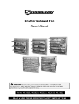
Fan Specifications: 60Hz shown (50Hz available)
Power: 230 VAC or 230/460 VAC
Phase: 1 or 3
HP1167 – 36”/48” Fan, One Piece Cone
ID Qty. Cat. No. Description
[A] 12 KS2105 #14 x 1.5” Lag Screw, SS
[B] 8 KS0650
1
⁄4”-20 x
7
⁄8” Truss Head Bolt, SS
[C] 8 KW3012
1
⁄4” x 1” O.D. Flat Washer, SS
[D] 8 KN1717
1
⁄4”-20 Hex Flange, Nylock Nut, SS
1.2 Fan Dimensions:

5© Munters Corporation, August 2018
QM1227r6
Installation Instructions
2.
2.1 Fan Installation
Step 1
Construct the framed opening to correct size according to the Chart A. See Figure 1A and 1B.
FAN DIA. CONE
WALL OPENING
(W. X H.)
MINIMUM SPACING 'Z'
CENTER TO CENTER
DIMENSION
36” 36RC
43” W. x 43” H.
12” recommended; 8”minimum 51” Minimum
48” 48RC
55” W. x 55” H.
12” recommended; 9” minimum 64” Minimum
Chart A
Figure 1B Post Construction
Figure 1A Frame Construction
Ceiling
Framing
H
(See chart A)
12"
W
(See chart A)
See minimum
spacing notes in
Chart A
Z
Top of Post Wall
H.
(See Chart A)
W.
(See Chart A)
6 x 6 Post - 6'O.C.
'Z'

© Munters Corporation, August 2018
6
QM1227r6
Figure 3
Wall Framing
2" Minimum Framing for fan, Bottom
WallOpening (See Chart A, Page 4)
4" Minimum Framing for fan,
Top and Sides
Wall Framing
Step 2B
If fan needs to be mounted, so that shutter does not stick into building then frame fan as shown in
Figure 3
.
Top and sides require 4" minimum and bottom requires 2" minimum.
Step 2A
Insert fan into the framed opening from the inside. While lifting fan up tight to framing, fasten top of
fan with (3) Lag Screw [A].
See Figure 2A and 2B
. Next, fasten bottom of fan, then both sides with
remaining (9) Lag Screw [A]. Install flashing around opening tight to fan and caulk around fan to seal.
Figure 2A - Frame Construction
OUTSIDE INSIDE
2 x 4 Framing
#14 x 1.5" Lag Screws [A]
#14 x 1.5" Lag Screws [A]
OUTSIDE INSIDE
Figure 2B - Frame Construction
Post
2 x 8 Banner Boards
2 x 8 Header Boards
Installation InstructionsChapter 2

7© Munters Corporation, August 2018
QM1227r6
Step 3
Installing the one piece cone may require 2 people. If temperature is above 50°F then proceed to
Step 5.
If temperature is below 50°F then proceed to
Step 4.
Step 4
Using Locking Sheet Metal Pliers bend the cone tabs outward to allow the cone to slide onto the fan easier.
See Figure 4.
Figure 4
Cone Tabs
Cone
Locking Sheet Metal Pliers
Cone Tab
Installation InstructionsChapter 2
Figure 5A
Figure 5B
Hole at 10 O'clock
Top Cone Tab
Cone
Flange Nut [D]
36/48RC Cone
(outside)
Fan Outlet
(inside)
Truss Head Bolt [B]
Washer [C]
Step 5
Look for the “TOP” label on the Polycone and set the top of the Polycone on top of the fan orifice and
install (2) Truss Head Bolts [B] through holes in fan outlet through the slots in the cone at about the
10 and 2 o’clock positions and fasten with Washers [C] and Flange Nuts [D]. Truss head of each
bolt must be on the inside of the fan outlet; washers and flange nuts must be on outside of cone.
See Figure 5A and 5B.
Finger tighten nuts only at this time.

© Munters Corporation, August 2018
8
QM1227r6
Figure 6
Remaining Holes
Cone
Step 6
Work down the sides of the cone, sliding the cone tabs onto the fan until the bottom tab is in place. Keep
pressure on the cone to make sure tabs stay on the fan. Install (6) Truss Head Bolts [B], Washers [C] and
Flange Nuts [D] in the remaining holes in the fan outlet and slots in the cone to finish securing cone to fan.
See Figure 5B and Figure 6.
Tighten all nuts at this time, making sure not to over tighten.
Installation InstructionsChapter 2
Figure 7
Step 7
The snap-in guard has a slight conical shape to it so, when installed the center of the guard should
protrude out slightly.
See Figure 7.
Cone
Guard
Note:
If installing your existing guard in the new
Polycone, then proceed to Step 9. If installing
the new snap-in guard then proceed to Step 7.

9© Munters Corporation, August 2018
QM1227r6
Figure 7B
Cone
Guard
Guard Tab
Guard Tab
Guard Slot in cone
Step 8
Starting at the bottom of the cone, locate one of the guard tabs and put the guard tab through the guard
slot in the cone.
See Figure 7B
. Then work up around the guard and install each of the other guard
tabs in each of the corresponding guard slots. Some force may be required to snap the last tab into the
last slot, pull out on the center of the cone while pushing in on the guard tab until it snaps into place.
Installation InstructionsChapter 2
Figure 8B
Guard Mounting
Pad
Figure 8A
Nut
Bolt
Guard Mounting Pad
Guard
Fan Outlet
Step 9
If installing your existing guard into the new cone, locate the flat guard mounting pads on the cone and
drill a
9
⁄32” dia. hole in the center of each pad. Then insert existing guard into cone with the guard eyelets
facing away from you. Line up each eyelet with a hole in the guard pads. Secure guard to cone using
(8) existing Bolts and Nuts.
See Figure 8A and 8B
. Tighten all nuts at this time.
Guard eyelet

© Munters Corporation, August 2018
10
QM1227r6
Installation InstructionsChapter 2
Figure 9
PT Shutter
2.2 PT Style Shutter
Fixed Bottom
Shutter Clip
Step 11
Fasten shutter in place by rotating the side and top shutter clips over the shutter flanges.
See Figure 10.
Installation is now complete, proceed to Electrical Wiring Section.
Figure 10
Note:
PT Shutter extends into room
2
5
⁄16” from back of fan.
Step 10
Insert PT Shutter into fan by sliding the bottom flange of shutter into
bottom shutter clips and pressing shutter inward.
See Figure 9.

11© Munters Corporation, August 2018
QM1227r6
Installation InstructionsChapter 2
2.3 PZ Style Shutter
PZ Shutter
Fixed Bottom
Shutter Clip
Figure 11B
Figure 11A
Step 12
Insert PZ shutter into fan by sliding the bottom flange of shutter into bottom shutter clips and pressing
shutter inward,
See Figure 11A
. Fasten shutter in place by rotating the side and top shutter clips over
the shutter flanges,
See Figure 11B.
Installation is now complete, proceed to electrical wiring section.

© Munters Corporation, August 2018
12
QM1227r6
Electrical Wiring
3.
3.1 Recommended Wire Routing
The Munters Drive Fan comes with a coil of electrical cable that is pre-wired to motor. Find the end of the cable
and route it outside the fan and connect it to the incoming power supply and/or the safety cut-off switch. (Safety
cut-off switch by others). See Figure 12A.
Electrical Cable
Junction Box
Figure 12A
WARNING: Fan is designed to be operated with shutter in place. Do not apply power to fan without
shutter being installed.

13© Munters Corporation, August 2018
QM1227r6
KEY:
L1=Line 1
L2=Line 2
L3=Line 3
H=Hot
N=Neutral
G=Ground
All wiring should be installed in accordance with National, State, and Local electrical
codes. Fans used to ventilate livestock buildings or other rooms where continuous air
movement is essential should be connected to individual electrical circuits, with a minimum
of two circuits per room. For electrical connection requirements, refer to diagram on motor
nameplate and to information enclosed with the environmental control to be used.
Single Phase and Three Phase Munters Drives: Power supply for fans to have Circuit
Breaker or Fuse Protection. The installer must refer to NEC and local codes to ensure
safety and compliance. See Figure 12B & 12C.
If recommended lightning protection was purchased, wire it to the fan power supply as shown and secure the
lightning protection unit near the disconnect or the bus panel. See Figure 12B & 12C.
NOTE: A safety cut-off switch should be located adjacent to each fan.
T1
T2
T3
G
Three Phase
Power Out to Fan Motor
Three Phase
Power Supply for Fan
L1
L2
L3
G
Safety
Cut-Off Switch
Recommended Lightning Protection
FC2003, 230V, 1 Phase
240 VAC
Power Supply for Fan
L1
L2
G
T1
T2
G
240 VAC
Power Out to Fan
Figure 12C
Three Phase
Figure 12B
Single Phase
Safety
Cut-Off Switch
Recommended Lightning Protection
FC2006, 230V, 3 Phase
FC2009, 460V, 3 Phase
3.2 Electrical Wiring
Electrical WiringChapter 3
WARNING
!
High Voltage, disconnect
power before servicing.

© Munters Corporation, August 2018
14
QM1227r6
3.3 Recommended Wiring
Electrical WiringChapter 3
‘RUN’ Switch
Figure 13A
Default Operation Full Speed
Circuit Board in Munters Drive Box
The Munters Drive fan ships configured for simple ON/OFF operation. When electrical power is applied to
the main cable and the ‘RUN’ Switch is in the ‘ON’ Position, the fan will start and run at full speed.
See Figure 13A.
***WARNING***
The Blue Box electrical enclosure must not be
removed from mounting bracket. Removing
Blue Box from the mounting bracket will void the
warranty. Any water or other damage to the
controller will not be covered if the Blue Box is
removed.
***NOTE***
All Low Voltage wire must be shielded
cable. i.e. Belden 8770 or equivalent.
WARNING: Fan is designed to be operated with shutter in place. Do not apply power to fan without
shutter being installed.

15© Munters Corporation, August 2018
QM1227r6
Electrical WiringChapter 3
When making connections to Munters Drive Box, be sure to use the supplied watertight fittings with only
1 cable per fitting. If watertight fittings are not used or if 2 cables or more are in 1 watertight fitting,
equipment failure from water damage will not be covered under warranty. If 2 or more cables are used in
1 watertight fitting, they must be sealed on both sides of
Munters Drive Box wall to prevent water infiltration.
If you are going to run the Munters Drive with a signal from a control, carefully remove 6 screws and the
cover and save to reinstall later. Carefully punch the knock-out from the bottom of the Munters Drive Box and
install the Watertight connector as shown. See Figure 13B and 13C.
Screw
Knock-out
Munters Drive Box Cover
Munters Drive Box
Munters Drive Box
Watertight Connector
Figure 13B
Figure 13C

© Munters Corporation, August 2018
16
QM1227r6
Electrical WiringChapter 3
Figure 13D
On/Off Remotely
Control
Relay
Junction Box
(By Others)
Munters Drive Box
‘RUN’ Switch
Munters Drive Box
Circuit Board in Munters Drive Box
To operate the Munters Drive On/Off with a control, Slide the ‘RUN’ switch, located on the circuit board in
the Munters Drive Box, to the ‘OFF’ position. Now wire an ‘ON’ command from the ‘COMMON’ terminal
to the input relay in the control and from the output of the control relay to the ‘RUN’ terminal in the Munters
Drive Box. See Figure 13A & 13D.
Jumpers
WARNING: Fan is designed to be operated
with shutter in place. Do not apply power to
fan without shutter being installed.
***WARNING***
The Blue Box electrical enclosure must not be
removed from mounting bracket. Removing
Blue Box from the mounting bracket will void the
warranty. Any water or other damage to the
controller will not be covered if the Blue Box is
removed.
***NOTE***
All Low Voltage wire must be shielded
cable. i.e. Belden 8770 or equivalent.

17© Munters Corporation, August 2018
QM1227r6
Electrical WiringChapter 3
To operate the Munters Drive Off/Low/High with a control, slide the ‘RUN’ switch, located on the circuit
board in the Munters Drive Box, to the ‘OFF’ position. Now wire an ‘ON’ command from the ‘COMMON’
terminal to the input relay in the control and from the output of the relay to the ‘RUN’ terminal in the Munters
Drive Box. Then connect the output of the control relay for ‘LOW’ to the ‘REDUCED FLOW’ terminal in the
Munters Drive Box. See Figure 13E.
Control
Relay
Munters Drive Box
‘RUN’ Switch
Circuit Board in Munters Drive Box
Figure 13E
Off/Low/High Remotely
WARNING: Fan is designed to be operated with shutter in place. Do not apply power to fan without
shutter being installed.
***WARNING***
The Blue Box electrical enclosure must not be
removed from mounting bracket. Removing
Blue Box from the mounting bracket will void the
warranty. Any water or other damage to the
controller will not be covered if the Blue Box is
removed.
***NOTE***
All Low Voltage wire must be shielded
cable. i.e. Belden 8770 or equivalent.

© Munters Corporation, August 2018
18
QM1227r6
Electrical WiringChapter 3
Figure 13F
Variable Speed Operation
To Operate the Munters Drive variable with a 10-0V Signal, slide the ‘RUN’ switch, located on the circuit
board in the Munters Drive Box, to the ‘ON’ position. Connect wires from the ‘0-10V IN’ and ‘0-10V
COMMON’ terminals in the Munters Drive Box to the 10-0V output in the control. See Figure 13F.
10-0V
Output
In Control
Junction Box
(By Others)
Munters Drive Box
‘RUN’ Switch
Circuit Board in Munters Drive Box
Jumper
WARNING: Fan is designed to be operated
with shutter in place. Do not apply power to
fan without shutter being installed.
***WARNING***
The Blue Box electrical enclosure must not be
removed from mounting bracket. Removing
Blue Box from the mounting bracket will void the
warranty. Any water or other damage to the
controller will not be covered if the Blue Box is
removed.
***NOTE***
All Low Voltage wire must be shielded
cable. i.e. Belden 8770 or equivalent.

19© Munters Corporation, August 2018
QM1227r6
Electrical WiringChapter 3
10-0V
Output
In Control
To operate the Munters Drive Off/Variable with a 10-0V Signal, slide the ‘RUN’ switch, located on the circuit
board in the Munters Drive Box, to the ‘OFF’ position. Now wire an ‘ON’ command from the ‘COMMON’
terminal to the input relay in the control and from the output of the control relay to the ‘RUN’ terminal in
the Munters Drive Box. Also, connect wires from the ‘0-10V IN’ and ‘0-10V COMMON’ terminals in the
Munters Drive Box to the 10-0V output in the control. See Figure 13G.
Figure 13G
On/Off with Variable Speed Operation
Control
Relay
Munters Drive Box
‘RUN’ Switch
Circuit Board in Munters Drive Box
WARNING: Fan is designed to be operated with shutter in place. Do not apply power to fan without
shutter being installed.
Munters Drive Box
Junction Box
(By Others)

© Munters Corporation, August 2018
20
QM1227r6
Operation and Maintenance
4.
1) INITIAL START-UP: With electrical power off, verify that the fan propeller
turns freely and that all fasteners are secure. With shutter in place, turn on
electrical power and confirm that the fan operates smoothly.
2) TEMPERATURE ADJUSTMENTS: Set the fan control to the temperature
shown on your Munters ventilation system drawing, or to a value which will
provide the desired environmental conditions.
4.1 Operation
WARNING
!
Moving parts, disconnect
power before servicing.
WARNING
!
High Voltage, disconnect
power before servicing.
WARNING
!
Do not power wash
electrical devices.
WARNING
!
Do not apply power
with shutter out.
4.2 Maintenance
The following inspection and cleaning procedures should be performed
monthly:
1) INSPECT PROPELLER: Check that propeller is secure on drive hub and that
there are no signs of damage. The blades are of a self-cleaning design and
should not require maintenance.
2) CLEAN regularly for best results:
• FAN MOTOR: Remove any dust accumulation from motor using a
brush or cloth. (DO NOT use a pressure washer). A clean motor will run
cooler and last longer. At the same time, verify that the motor is secure in
its mount.
• SHUTTER: Carefully clean dust from shutter and frame so that shutter
opens and closes freely. A brush or cloth should be used.
• GUARD: Clean any dust or feathers from fan guards using a brush.
Dirty guards can reduce airflow.
3) CHECK FASTENERS: For safety, all fasteners should be inspected. Tighten
any loose connections.
4) INSPECT FAN CONTROL: With power disconnected, inspect all electrical
connections. Wiring should be secure and in good condition. Remove any
dust build-up from control case and sensor using a soft brush or cloth.
NEVER CLEAN ELECTRICAL EQUIPMENT WITH A PRESSURE WASHER!
/