Chore-Time MV1089C 14-, 18-, & 24-Inch Direct Drive TURBO® Hooded Fans Installation and Operators Instruction Manual
- Type
- Installation and Operators Instruction Manual

MV1089CMarch 2004
TURBO
®
Hooded Fans
Installation & Operator’s Manual
(14”, 18”, & 24” Direct Drive)

14”, 18”, & 24” Hooded Fan Operator’s Manual • Page 2
WARRANTY INFORMATION
Chore-Time Equipment warrants new TURBO
®
Fans and components manufactured by it to be free from
defects in material or workmanship from the date of initial installation by the original purchaser until
expiration of the appropriate period set forth below. If such a defect is found by Chore-Time to exist within
the applicable period, Chore-Time will, at its option, (a) repair or replace such product free of charge, F.O.B.
the factory of manufacture, or (b) refund to the original purchaser the original purchase price, in lieu of such
repair or replacement. The extended warranty is provided to the original purchaser for the following periods:
*1. TURBO
®
Fan fiberglass housings and cast aluminum blades - for as long as the original purchaser
owns the product.
*2. TURBO
®
Fan motors and bearings - for two years from date of installation.
*3. TURBO
®
Fan components, including plastic shutters and polyethylene cones - for three years from
date of installation.
Conditions and Limitations
1. The product must be installed by and operated in accordance with the instructions published by the
Manufacturer or Warranty will be void.
2. Warranty is void if all components of the system are not original equipment supplied by the
Manufacturer.
3. This product must be purchased from and installed by an authorized distributor or certified
representative thereof or the Warranty will be void.
4. Malfunctions or failure resulting from misuse, abuse, negligence, alteration, accident, or lack of
proper maintenance shall not be considered defects under the Warranty.
5. This Warranty applies only to systems for the care of poultry and livestock. Other applications in
industry or commerce are not covered by this Warranty.
The Manufacturer shall not be liable for any Consequential or Special Damage which any
purchaser may suffer or claim to suffer as a result of any defect in the product. “Consequential” or
“Special Damages” as used herein include, but are not limited to, lost or damaged products or goods,
costs of transportation, lost sales, lost orders, lost income, increased overhead, labor and incidental
costs and operational inefficiencies.
THIS WARRANTY CONSTITUTES THE MANUFACTURER’S ENTIRE AND SOLE WARRANTY AND
THIS MANUFACTURER EXPRESSLY DISCLAIMS ANY AND ALL OTHER WARRANTIES,
INCLUDING, BUT NOT LIMITED TO, EXPRESS AND IMPLIED WARRANTIES AS TO
MERCHANTABILITY, FITNESS FOR PARTICULAR PURPOSES SOLD AND DESCRIPTION OR
QUALITY OF THE PRODUCT FURNISHED HEREUNDER.
Chore-Time Distributors are not authorized to modify or extend the terms and conditions of this
Warranty in any manner or to offer or grant any other warranties for Chore-Time products in addition
to those terms expressly stated above. An officer of CTB, Inc. must authorize any exceptions to this
Warranty in writing. The Manufacturer reserves the right to change models and specifications at any
time without notice or obligation to improve previous models.

14”, 18”, & 24” Hooded Fan Operator’s Manual • Page 3
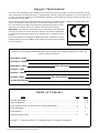
(CE-mark serial number)
Support Information
The Chore-Time Hooded Fans are designed to be used as exhaust fans in highly corrosive environments. The pri-
mary components are made from plastic or stainless steel materials. Using this equipment for any other purpose or
in a way not within the operating recommendations specified in this manual will void the warranty and may cause
personal injury and/or death.
This manual is designed to provide comprehensive planning, installation, wiring, operation, and parts listing infor-
mation. The Table of Contents provides a convenient overview of the informa-
tion in this manual. The Table of Contents also specifies which pages contain
information for the sales personnel, installer, and consumer (end user).
IMPORTANT: CE stands for certified Europe. It is a standard which equipment
must meet or exceed in order to be sold in Europe. CE provides a benchmark
for safety and manufacturing issues. CE is required only on equipment sold in
Europe.
Chore-Time Equipment recognizes CE Mark and pursues compliance in all ap-
plicable products. Fill in the CE-Mark serial number in the blank space provided
for future reference.
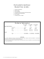
Please fill in the following information about your Hooded Fans. Keep this manual in a clean, dry
place for future reference.
Distributor’s Name
Distributor’s Address
Distributor’s Phone Date of Purchase
Installer’s Name
Installer’s Address
Installer’s Phone Date of Installation
System Specifications
Table of Contents
Topic Page User*
Warranty Information..................................................................................................................2 C, D
Support Information ....................................................................................................................3 C, D
Tools needed to install your Hooded Fans, Technical Information ............................................4 I
Safety Information.......................................................................................................................5 C, I
Fan Installation ............................................................................................................................6 I
Hooded Fan Parts Listing ............................................................................................................8 C, D
*Legend: C = Customer (end user), D = Distributor (sales), I = Installer of equipment

14”, 18”, & 24” Hooded Fan Operator’s Manual • Page 4
Tools needed to install your
Hooded Fans include:
1. Regular Screwdriver
2. Wire Cutters
3. Wire Strippers
4. Adequate Size and Quantity of Electrical Wire
5. Electrical Drill and Drill Bits
6. 5/16” Socket
7. Another person to help!!
Technical Information
14” Hooded 18” Hooded 24” Hooded
Fan Fan Fan
Motor Specifications:
Horsepower - - - - - - - - - - - - - 1/8 H.P. 1/4 H.P. 1/3 H.P.
Voltage - - - - - - - - - - - - - - - 230 V 230 V 230 V
Hz. - - - - - - - - - - - - - - - - - 60 Hz. 60 Hz. 60 Hz.
Phase - - - - - - - - - - - - - - - - Single Phase Single Phase Single Phase
R.P.M. - - - - - - - - - - - - - - - - 1625 R.P.M. 1625 R.P.M. 1075 R.P.M.
Blade:
Size - - - - - - - - - - - - - - - - - 14” (356 mm) 18” (457 mm) 24” (610 mm)
Type- - - - - - - - - - - - - - - - - Cast Aluminum Cast Aluminum Cast Aluminum
Important
Chore-Time Equipment strongly recommends that a good alarm system should be installed in confinement
buildings to warn of power failure and high temperature.
Chore-Time Equipment also recommends that an alternate power source be available for confinement buildings
in case of power failure.

14”, 18”, & 24” Hooded Fan Operator’s Manual • Page 5
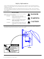
Safety Information
Caution, Warning and Danger Decals have been placed on the equipment to warn of potentially dangerous
situations. Care should be taken to keep this information intact and easy to read at all times. Replace missing
or damaged safety signs.
Chore-Time equipment is designed to be installed and operated as safely as possible...however, hazards do
exist. Using the equipment for purposes other than specified in this manual may cause personal injury or damage
to the equipment.
DANGER
WARNING
CAUTION
SIGNAL WORDS
Signal words are used in conjunction with the safety–alert symbol to
identify the severity of the warning.
DANGER.......... indicates an imminently hazardous
situation which, if not avoided, WILL result
in death or serious injury.
WARNING ....... indicates a potentially hazardous situation
which, if not avoided, COULD result in
death or serious injury.
CAUTION ........ indicates a hazardous situation which, if not
avoided, MAY result in minor or moderate
injury.
This diagram shows the proper location of the safety decals as shipped from the factory. Replace damaged or
missing decals. Make sure the decals may be easily seen at all times.

14”, 18”, & 24” Hooded Fan Operator’s Manual • Page 6
Fan Installation
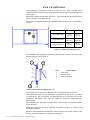
The installation procedure is similar for the 14”, 18”, & 24” Hooded Fans,
unless otherwise noted. The primary difference is the size of opening required.
See Figure 1.
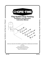
Build wall framing as specified in Figure 1. The required wall opening for each
fan is included in the chart below.
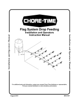
The Fans are shipped completely assembled and need only to be fastened to
the wall.
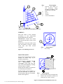
The Hardware Kit, supplied, includes (8) #10 screws to secure the fan to the
framed opening. See Figure 2.
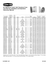
The Plastic Hood should be installed over the fan as shown in Figure 3.
Note: Make sure the Hood is positioned as specified in Figure 3. If the Hood
is installed too low on the fan, the Blow-Out Door (on the fan) will not be
allowed to completely open. This will restrict air flow and compromise fan
performance.
The Hardware Kit, supplied, includes the 2” screws used to secure the Hood
to the building.
Install the Guard on the Hood opening, as shown in Figure 3, using 1/4-20
hardware supplied.
Slide the screen between the flanges on the incoming end of fan. Caution: The
Screen must be installed to prevent serious injury.
Figure 1. Framing Diagram (front view).
Dimension A B
14” Hooded Fan
17.75”
(45 cm)
17.75”
(45 cm)
18” Hooded Fan
22.25”
(56.5 cm)
22.25”
(56.5 cm)
24” Hooded Fan
28.75”
(73 cm)
28.75”
(73 cm)
Figure 2. Hooded Fan Installation (side view)
Key Description
1Side Wall
2 Hooded Fan
3 (8) #10 Screws

14”, 18”, & 24” Hooded Fan Operator’s Manual • Page 7
WIRING:
Wire the motor to fan controls
according to the instructions
packed with the fan controls.
IMPORTANT: Route the motor
cord out through the corner of the
Shroud.
Fasten the cord to the side of the
Fan, as shown in Figure 4, using
Cord Clip and #10 screw,
included.
MAINTENANCE:
Service and maintenance of fans
should be done only by a
qualified technician.
DISCONNECT POWER PRIOR
TO MAINTAINING OR
CLEANING THE FAN! The fan
may start automatically causing
serious injury or death.
Keep the fan clean for maximum
life and best performance.
During winter (cold weather), it
may be desirable to replace the
Screen with a piece of insulation
board. See Figure 5.
Key Description
1 Cord Clip
Figure 4. Cord Routing (front view)
Key Description
1 Secure the Hood to
the building using
screws provided in the
Hardware Package.
2Fan
3 Hood
4 Guard
5 1/4-20 Hardware
Figure 3. Hood and Guard Installation (side view)
Key Description
1 Insulation Board (not supplied)
2 Notch the insulation board as
required for cord routing.
Figure 5. Insulation Board Installation (front view)

14”, 18”, & 24” Hooded Fan Operator’s Manual • Page 8
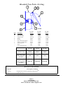
14” Fan 18” Fan 24” Fan
Item Description Part No. Part No. Part No.
1 Fan Housing 35244 35254 30610
2 S.S. Clevis Pin 35662 35662 35662
3 Danger Decal 2527-50 2527-50 2527-50
4 Motor 35996 35997 35661
5 Screen 35671 35672 35660
6 Motor Mount Weldment 35380 35372 38343
7 Blade (cast aluminum) 38346 38342 38341
8 S.S. Bridge Pin 35993 35993 35993
-- Hood 7442 6948 6950
-- Cover Guard (Screen) 7374 7440 7009
14” Fan 18” Fan 24” Fan
Hooded Fan
(Items 1 - 8)
35703 35702 35650
Fan Cover, Cover
Guard, & Mounting
Hardware
7441 7106 7027
Hooded Fan, Fan
Cover, Cover
Guard, & Mounting
Hardware
36760-142 36760-182 36760-242
Hooded Fan Parts Listing
Contact your nearby Chore-Time distributor or representative for additional parts and information.
CTB, Inc.
P.O. Box 2000
Milford, Indiana 46542-2000 U.S.A.
Phone: 574-658-4101 • E-Mail: [email protected]
Revisions to this Manual
Page No Description of Change
Various Changed Turbo from tm (trademark) to Registered.
®
Page 2 Updated Warranty
-
 1
1
-
 2
2
-
 3
3
-
 4
4
-
 5
5
-
 6
6
-
 7
7
-
 8
8


Chore-Time MV1089C 14-, 18-, & 24-Inch Direct Drive TURBO® Hooded Fans Installation and Operators Instruction Manual
- Type
- Installation and Operators Instruction Manual
Ask a question and I''ll find the answer in the document
Finding information in a document is now easier with AI
Related papers
-
 Chore-Time MV1089B 14-, 18-, & 24-Inch Direct Drive TURBO® Hooded Fans Installation and Operators Instruction Manual
-
 Chore-Time MV1708B TURBO-COOL™ Splash Guard Installation guide
-
 Chore-Time 75 Installation and Operators Instruction Manual
-
 Chore-Time MA1015F FLAG™ System Drop Feeding Installation and Operators Instruction Manual
-
 Chore-Time MF1851B CPF Feeding System Installation and Operators Instruction Manual
-
 Chore-Time MV1892H 48-Inch Belt Drive TURBO® Installation and Operators Instruction Manual
-
 Chore-Time MF174R MODEL C™ Feeding System Installation and Operators Instruction Manual
-
 Chore-Time MV1892B 48-Inch Belt Drive TURBO® Fan Installation and Operators Instruction Manual
-
 Chore-Time MV1892F 48-Inch Belt Drive TURBO® Installation and Operators Instruction Manual
-
 Chore-Time MT2398C CHORE-TRONICS® 3 Control Installation and Operators Instruction Manual


Other documents
-
Builders Edge 140056774069 Installation guide
-
-
-
-
Greenheck 455305 Hooded Propeller Fans Operating instructions
-
Rubbermaid Commercial Products FG9T6400BLA User manual
-
CFM HRV-60 User manual
-
York HOODED ROOF MOUNT PROP FANS User guide
-
Broan Tile-Lined Masonry Chimney Kit Installation guide
-