Page is loading ...

AMERICAN Flow Control Page 5A-2
Tapping Valves
AMERICAN Flow Control
TAPPING VALVES
The AMERICAN Series 2500 is available in tapping
congurations in sizes 4 in.–48 in. The tapping valve is
provided with a rated working pressure of 250 psig and is
designed for use in drinking water, sewage, re protection
systems, as well as irrigation systems.

AMERICAN Flow Control
Page 5A-3
Tapping Valves
4 in.–36 in. valves meet or exceed requirements of ANSI/AWWA C515.
4 in.–16 in. valves may be ordered in congurations which are UL Listed and Approved by FM Approvals.
18 in.–24 in. valves may be ordered in congurations which are UL Listed.
4 in.–48 in. valves have 250 psig AWWA rated working pressure.
4 in.–12 in. valves in Listed and Approved congurations have 250 psig UL and FM rated working pressure.
14 in. and 16 in. valves in Listed and Approved congurations have 200 psig UL and FM rated working pressure.
18 in.–24 in. valves in Listed congurations have 175 psig UL rated working pressure.
Fusion bonded epoxy coating meets or exceeds requirements of ANSI/AWWA C550.
Mechanical joint ends are in accordance with ANSI/AWWA C153/A21.53 and MSS SP-113.
Bolt patterns of anged ends are in accordance with ANSI/AWWA C110/A21.10.
Raised pilot dimensions of anged ends on tapping valves are in accordance with MSS SP-60.
Tapping valves are supplied with anged-end hardware, including bolts, nuts, ring-type gasket and ange protection kit. The ange-end bolting is
furnished in the same material as specied for the valve body bolting.
4 in.–48 in. valves are Certied to NSF/ANSI Standard 61 and NSF/ANSI 372.
NOTES:
Dimension Valve Size
Series 2500-1 Series 2500
4” 6” 8” 10” 12” 14” 16” 18” 20” 24”
A 13.91 17.12 20.47 24.06 27.59 33.25 36.75 39.62 43.25 51.25
B +.000/- .031 4.984 6.984 8.984 10.984 12.984 14.937 16.937 18.937 20.937 24.937
C +/- .016 .188 .250 .250 .250 .250 .250 .250 .250 .250 .250
D (Flange End) (TF) (Class 125) 4.50 5.25 5.75 6.50 7.00 7.50 8.00 8.50 9.00 10.00
E (MJ End) MJ 5.00 5.25 6.62 7.12 7.38 10.25 10.44 11.44 11.75 12.75
F 2.50 2.50 2.50 2.50 2.50 3.50 3.50 3.50 3.50 3.50
G Waterway Diameter 4.25 6.25 8.25 10.25 12.25 14.19 16.19 18.12 20.12 24.12
H 3.73 3.84 4.94 5.30 5.38 7.62 7.56 8.44 8.62 9.00
No. of turns to open 14 20 26 32 38 44 50 56 62 76
Tap Size 3/8 NPT 3/8 NPT 3/8 NPT 3/8 NPT 3/8 NPT 3/8 NPT 3/8 NPT 3/8 NPT 3/8 NPT 3/8 NPT
Max. Cutter Diameter 4.00 6.00 8.00 10.00 12.00 14.00 16.00 18.00 20.00 24.00
SERIES 2500 - TAPPING VALVE DIMENSIONS, 4”–24” SIZES
1.
2.
3.
4.
5.
6.
7.
8.
9.
10.
11.
12.
13.

AMERICAN Flow Control Page 5A-4 Tapping Valves
SERIES 2500 - TAPPING VALVE WITH BEVEL GEARING DIMENSIONS, 14”–48” SIZES
Dimension
Valve Size
Series 2500
14” 16” 18” 20” 24” 30” 36” 42” 48”
A 35.19 39.75 43.00 44.44 52.62 62.62 74.38 86.28 96.00
B 9.50 9.50 9.50 10.38 10.38 13.56 15.38 19.19 19.19
C +.000/- .031 14.937 16.937 18.937 20.937 24.937 30.937 36.937 43.437 49.437
D +/- .016 .250 .250 .250 .250 .250 .516 .516 .516 .516
E (Flange End) (TF) (Class 125) 7.50 8.00 8.50 9.00 10.00 13.00 15.00 19.00 21.50
F (MJ End) MJ 10.25 10.44 11.50 11.75 12.81 16.88 18.75 23.38 22.50
G 3.50 3.50 3.50 3.50 3.50 4.00 4.00 4.00 4.00
H Waterway Diameter 14.19 16.19 18.12 20.12 24.12 30.22 36.19 42.38 48.38
J 7.62 7.56 8.44 8.62 9.00 12.88 13.97 17.88 17.00
No. of turns to open 88 100 112 186 228 379 448 694 789
Tap Size 3/8 NPT 3/8 NPT 3/8 NPT 3/8 NPT 3/8 NPT 3/8 NPT 3/8 NPT 1/2 NPT 1/2 NPT
Max. Cutter Diameter 14.00 16.00 18.00 20.00 24.00 30.00 36.00 42.00 48.00

AMERICAN Flow Control Page 5A-5
Tapping Valves
SERIES 2500 - CLASS 125 FLANGE DIMENSIONS
NOTES:
1. Flange dimensions shown are per ASME B16.1, Class 125 for cast iron anges and ANSI/AWWA C110/A21.10. Flange thickness tolerances
shown are per ANSI/AWWA C110/A21.10.
2. Bolt lengths shown are for standard cast iron ange thicknesses with through holes. Steel or ductile iron anges with reduced thickness or valves or
ttings with tapped holes may require shorter bolts.
Model
Valve
Size
A B C D E F
Diameter
of Flange
Flange
Thick-
ness
Bolt
Circle
Diameter
Bolt Holes
Bolt
Size
Bolt
Length
Stud
Length
No.
Bolts
No.
Studs
No. of Hex Nuts
Required
No. Size (See Note 2)
Series
2500
14” 21.00 1.38±.19 18.75 12 1.12 1”-8 4-1/2 5-1/2 4 8 20
16” 23.50 1.44±.19 21.25 16 1.12 1”-8 4-1/2 5-1/2 8 8 24
18” 25.00 1.56±.19 22.75 16 1.25 1-1/8-7 5 6 8 8 24
20” 27.50 1.69±.19 25.00 20 1.25 1-1/8-7 5 6 12 8 28
24” 32.00 1.88±.19 29.50 20 1.38 1-1/4-7 5-1/2 6-1/2 12 8 28
30” 38.75 2.12±.25 36.00 28 1.38 1-1/4-7 6-1/2 7-1/2 20 8 36
36” 46.00 2.38±.25 42.75 32 1.62 1-1/2-6 7 8 24 8 40
42” 53.00 2.62±.25 49.50 36 1.62 1-1/2-6 N/A 9-1/2 N/A 36 72
48” 59.50 2.75±.25 56.00 44 1.62 1-1/2-6 N/A 9-1/2 N/A 44 88
NOTES:
1. Flange dimensions shown are per ASME B16.1, Class 125 for cast iron anges and ANSI/AWWA C110/A21.10. Flange thickness tolerances shown
are per ANSI/AWWA C110/A21.10.
2. Bolt lengths shown are for standard cast iron ange thicknesses with through holes. Steel or ductile iron anges with reduced thickness or valves or
ttings with tapped holes may require shorter bolts.
Model
Valve
Size
A B C D E F
Diameter of
Flange
Flange
Thickness
Bolt Circle
Diameter
Bolt Holes
Bolt Size See
Note 2
No. of Hex Nuts
Required
No. Size
Series
2500-1
4” 9.00 .94±.12 7.50 8 .75 5/8-11 x 3 8
6” 11.00 1.00±.12 9.50 8 .88 3/4-10 x 3-1/2 8
8” 13.50 1.12±.12 11.75 8 .88 3/4-10 x 3-1/2 8
10” 16.00 1.19±.12 14.25 12 1.00 7/8-9 x 4 12
12” 19.00 1.25±.12 17.00 12 1.00 7/8-9 x 4 12

AMERICAN Flow Control Page 5A-6
Tapping Valves
SERIES 2500 - MECHANICAL JOINT ACCESSORIES
Model
Pipe
or
Valve
Size
Gland Gasket T-Head Bolt
A
Dia.
B
Dia.
C Diameter
D
E F Dia. G H
Qty. Size Length
Std.
Gland
Pit-Cast
Gland
Qty. Size Standard
Gasket
Transition
Gasket
Standard
Gasket
Transition
Gasket
Standard
Gasket
Transition
Gasket
Series
2500-1
4” 9.12 7.50 4.90 5.13 .75 4 .88 4.68 4.43 .62 .77 1.22 1.26 4 3/4-10 3-1/2”
6’ 11.12 9.50 7.00 7.24 .88 6 .88 6.73 6.53 .62 .76 1.22 1.25 6 3/4-10 3-1/2”
8’ 13.37 11.75 9.15 9.46 1.00 6 .88 8.85 8.50 .62 .82 1.22 1.27 6 3/4-10 4”
10” 15.62 14.00 11.20 11.53 1.00 8 .88 10.87 10.59 .62 .79 1.22 1.26 8 3/4-10 4”
12” 17.88 16.25 13.30 13.63 1.00 8 .88 12.95 12.56 .62 .84 1.22 1.28 8 3/4-10 4”
Series
2500
14” 20.25 18.75 15.44 N/A 1.25 10 .88 14.99 N/A .62 N/A 1.22 N/A 10 3/4-10 4-1/2”
16” 22.50 21.00 17.54 N/A 1.31 12 .88 17.07 N/A .62 N/A 1.22 N/A 12 3/4-10 4-1/2”
18” 24.75 23.25 19.64 N/A 1.38 12 .88 19.13 N/A .62 N/A 1.22 N/A 12 3/4-10 4-1/2”
20” 27.00 25.50 21.74 N/A 1.44 14 .88 21.20 N/A .62 N/A 1.22 N/A 14 3/4-10 4-1/2”
24” 31.50 30.00 25.94 N/A 1.56 16 .88 25.34 N/A .62 N/A 1.22 N/A 16 3/4-10 5”
30” 39.12 36.88 32.17 N/A 2.00 20 1.12 31.47 N/A .73 N/A 1.54 N/A 20 1”-8 6”
36” 46.00 43.75 38.47 N/A 2.00 24 1.12 37.67 N/A .73 N/A 1.54 N/A 24 1”-8 6”
42” 53.12 50.62 44.67 N/A 2.00 28 1.38 43.78 N/A .73 N/A 1.54 N/A 28 1-1/4-7 6-1/2”
48” 60.00 57.50 50.97 N/A 2.00 32 1.38 49.98 N/A .73 N/A 1.54 N/A 32 1-1/4-7 6-1/2”
NOTES:
1. Dimensions shown for standard glands and gaskets are in accordance with ANSI/AWWA C111/A21.11 and
ANSI/AWWA C153/A21.53.
2. Dimensions shown are nominal.
3. T-head bolts and nuts are high-strength, low-alloy steel.
4. Glands are ductile iron.

AMERICAN Flow Control Page 5A-7
Tapping Valves
TAPPING VALVE WEIGHTS
Valves
NOTE: All weights are in pounds.
End
Connections
Valve Size
Series 2500-1 Series 2500
4” 6” 8” 10” 12” 14” 16” 18” 20” 24” 30” 36” 42” 48”
FL x MJ (Tapping) 64 102 162 246 365 670 820 1100 1520 2300 4100 7450 11279 15870

AMERICAN Flow Control
Page 5A-8
Tapping Valves
AMERICAN Flow Control®
TAPPING VALVE
SUBMITTAL SHEET
City Specication:
Qty.
4” 6” 8” 10” 12” 14” 16” 18” 20” 24” 30” 36” 42” 48”
Actuator (Check One)
NRS with 2” Sq. Oper. Nut
4” - 12” Valves Only
NRS with Enclosed Miter Gearing
Also Specify
2” Sq. Oper. Nut Parallel to Waterway
2” Sq. Oper. Nut Perpendicular to Waterway
14” - 48” Valves Only Also Specify
NRS with Bevel Gears 2” Sq. Oper. Nut Handwheel
Open Direction: Left (C.C.W.) Right (C.W.)
End Connections:
Mechanical Joint Accessories:
UL Listed, FM Approved:
Other Requirements (List on a Separate Sheet):
AMERICAN Flow Control®
American-Darling Valve & Waterous
A Division of AMERICAN
Available
Congurations
Series 2500 Ductile Iron
Resilient Wedge
Series 2500-1 Series 2500
4” 6” 8” 10” 12” 14” 16” 18” 20” 24” 30” 36” 42” 48”
ACTUATORS
NRS with 2” Sq. Oper. Nut X X X X X X X X X X N/A N/A N/A N/A
NRS with Handwheel X X X X X X X X X X N/A N/A N/A N/A
NRS with Enclosed Miter Gearing X X X X X N/A N/A N/A N/A N/A N/A N/A N/A N/A
NRS with Bevel Gears N/A N/A N/A N/A N/A X X X X X X X X X
END CONNECTIONS
Flange x Mech Joint (FL x MJ, Tap) X X X X X X X X X X X X X X
KEY: X = Available N/A = Not Available
NOTES:
Maximum Shell Cutter Size That May Be Used
Series 2500-1 Series 2500
4” 6” 8” 10” 12” 14” 16” 18” 20” 24” 30” 36” 42” 48”
Full Size May be Used
Visit our website at http://www.american-usa.com/afc
Series 2500 - Meets or exceeds requirements of ANSI/AWWA C515 (4 in. - 36 in.), 250 psig rated working pressure, is NSF/ANSI Standard 61 and
NSF/ANSI 372 (4 in.–48 in.), and has fusion bonded epoxy coating which meets or exceeds ANSI/AWWA C550. 4 in.–16 in. valves may be ordered
in congurations which are UL Listed and Approved by FM Approvals. 18 in.–24 in. valves may be ordered in congurations which are UL Listed.
Shell cutter sizes that can be used are as follows:
1.
2.

AMERICAN Flow Control Page 5A-9
Tapping Valves
TAPPING VALVE INSTALLATION AND TESTING
Note: Use only water to test the tapping valve and
sleeve assembly. Under no circumstance should
air ever be used to conduct this test. Testing with
air could result in serious injury and/or even death.
Place gasket on tapping valve and bolt valve to sleeve.
After valve is bolted securely in place, open valve
fully and observe that the resilient wedge is clear of the
waterway. Then close valve completely. Also refer to
anged end valve installation instructions if installing a
Series 2500 Resilient Wedge Tapping Valve.
Safely install proper blocking under valve and behind
sleeve to carry pipe thrust.
Prior to making the tap, test the tapping valve and
sleeve as a complete unit by connecting the test
pressure to the pipe tap on the back of the tapping
sleeve. Always test with water. Test pressure must not
exceed rated working pressure of the sleeve or valve.
The pressure test should reveal any leaks or other
problems caused by improper installation of the sleeve.
Any leaks or other problems must be remedied before
the pipe is tapped. If sleeve has no test plug, test sleeve
and valve assembly through test plug in valve bonnet
with the wedge in open position
Attach tapping machine to valve, making sure
machine is centered and square with the end of
the valve to assure straight travel of cutter through
valve. With tapping machine attached and cutter fully
retracted, check to be sure the valve can be closed
completely, then open the valve fully.
Final check before tapped: Open the valve fully. Make
sure the cutter does not damage gate or seats of valve
(or touch any interior surface of a resilient wedge
tapping valve). If any resistance is felt when hand
feeding the cutter into position, stop and correct before
making the tap.
Full size cutters may be used with the following Series:
• Series 2500-1: 4 in.–12 in. sizes
• Series 2500: 14 in.–48 in. sizes
1.
2.
3.
4.
5.
Valves are palletized when shipped, which provides
suitable protection from weather and sunlight during storage.
If palletizing is disbanded and valves removed, remaining
valves should be suitably covered or stored elsewhere with
the valve stem vertical.
● Always store valves fully closed.
● When possible, keep valves out of the weather.
● In cold climates, keep the inside of the valve drained of
any water to prevent freezing.
● Whenever possible, cover valves with a waterproof
covering.
● Protect all parts of the valve at all times
Storage
Inspection Before Installation
Check to make sure that the valve end connections
are clean and that the valve is not damaged.
Check opening direction and other details against
specication.
Open and close the valve to make sure it works
properly.
Clean the inside of the valve to remove all
contaminants that may affect water system purity.
Keep the valve closed when placing in trench.
●
●
●
●
AMERICAN recommends the use of AMERICAN Flow
Control Series 2800 tapping sleeves. Please refer to
Section 6A of the AMERICAN Valve and Hydrant Manual for
tapping sleeve installation instructions. In cases, where
other tapping sleeve designs or manufacturers are used,
please contact that manufacturer for specic tapping
sleeve installation and testing instructions. Applicable
tapping sleeve dimensions should be in compliance with the
Standard Practice as dened in MSS SP-60. AMERICAN
will not be responsible for claims, errors or omissions in
documentation provided by other manufacturers.
WARNING: Use only water to test the tapping valve and
sleeve assembly. Under no circumstance should air ever
be used to conduct this test. Testing with air could result in
serious injury or death.

AMERICAN Flow Control Page 5A-10
Tapping Valves
BALL VALVE INSTALLATION AND TESTING, 14”–48” SIZES
All tapping valves with bevel gears (for horizontal installa-
tion) will be furnished with tapped and plugged holes, and a
pipe nipple and ball valve for ushing. All tapping valves for
vertical installation will have tapped and plugged holes but
will not be furnished with pipe nipple and ball valve since
ushing should not be necessary for vertical installations.
When a valve is installed horizontally, the pipe plug on the
lower side of the valve body must be removed and the nipple
and ball valve installed. After the tap is made, the ball valve
should be used to ush any tapping debris (shavings) out of
the track area of the valve as it is being closed.
AMERICAN will not accept responsibility for problems
encountered if a horizontal tap is made with a valve
that does not have the nipple and ball valve ushing
connection.
Valves furnished without tapped and plugged holes should
not be tapped in the eld for installation of the ball valve
assembly.
The following procedure should be followed to ush the
interior of the tapping valve to remove shavings that could
affect closure of the valve.
After the main valve has been installed and prior to
adding pressure on the tapping sleeve, remove the
lower pipe plug from the bottom of the main valve.
Install the pipe nipple and the ball valve using Teon
tape or other pipe sealing compound. Make sure the
ball valve handle opens away from the body of the
tapping valve.
It is good practice at this point to cap the end of
the main valve in the open position and test the
system, including the main valve, ball valve and
tapping sleeve to ensure all seals are watertight.
1.
2.
3.
4.
5.
6.
7.
8.
9.
Note: Use only water to test the tapping valve and
sleeve assembly. Under no circumstance should
air ever be used to conduct this test. Testing
with air could result in serious injury and/or even
death.
Once the wet tap has been made and the tapping
cutter and coupon have been extracted from the main
valve waterway, begin closing the main valve.
When the main valve is approximately halfway
closed, open the ball valve and ush the line for
several seconds, then close the ball valve.
When the main valve is nearly closed or when torque
increase is rst noticed through the actuator, open the
ball valve and ush again for several seconds or until
the color of the water clears, then close the ball valve.
Apply necessary torque to the actuator to seal
the main valve. Care should be taken not to
over-torque the valve as damage may result. Torque
may vary. Contact AMERICAN Flow Control with any
questions.
Once the tap is complete and the tapping machine
has been removed, remove the handle of the ball
valve and install the pipe plug (from Step #1) in the
end to prevent dirt from getting into the ball valve.
Use care during backlling to prevent damage to the
ball valve and pipe nipple.
WARNING: Use only water to test the tapping valve and
sleeve assembly. Under no circumstance should air ever
be used to conduct this test. Testing with air could result in
serious injury or death.

AMERICAN Flow Control Page 5A-11
Tapping Valves
SERIES 2500 - OPERATION & MAINTENANCE
Operation Spare Parts
1.
2.
3.
4.
5.
6.
7.
1.
2.
Direction of opening is normally indicated by an
arrow cast on the handwheel or wrench nut of the
valve.
Operate gate valves from full closed to full open
position and back before applying pressure.
Close gate valve slowly against pressure to avoid
damage from surge or water hammer.
Valves installed on liquid service subject to
freezing conditions should be protected to prevent
trapping of liquid in the bonnet cavity, expansion
on freezing and subsequent damage. The same
is true of valves which are subject to considerable
temperature increases. Trapped pressure should
be vented back to the upstream side to prevent
buildup of pressure in the valve bonnet due to
high temperature expansion.
Valves should be opened and closed without the
use of excessive torque applied to the handwheel
or wrench nut. Excessive torque may damage the
valve.
Gate valves are designed for open and close
service. Their multi-turn design is not intended for
throttling. As such, the valve should never be left
in a partial open or closed position for extended
periods.
For troubleshooting information, please refer to
Section 3A of the AMERICAN Valve and Hydrant
Manual.
Under most conditions, the only spare parts needed for
the valve would be upper and lower stem O-rings. Under
rigorous service, stems, wedges, upper and lower stem
O-rings and thrust washers should be carried as spare
parts.
Use parts list drawings as a guide for disassembly and
ordering repair parts. Also refer to disassembly/reassem-
bly instructions.
Typical Operating Torque At
Rated Working Pressure
Valve Size Closing Torque
Ft-lbs
Opening Torque
Ft-lbs
2” 15-20 15-20
2-1/2” 15-20 15-20
3” 30-40 30-40
4” 30-40 30-40
6” 50-60 50-80
8” 70-80 60-90
10” 90-100 125-150
12” 100-125 140-175
14” Contact Factory
16” Contact Factory
18” Contact Factory
20” Contact Factory
24” Contact Factory
30” Contact Factory
36” Contact Factory
42” Contact Factory
48” Contact Factory
Maintenance
1.
2.
3.
WARNING: Special care should be taken in the installation, inspection and repair of pressure containing
devices such as valves and hydrants. FAILURE TO FOLLOW PROPER PRACTICE AND GUIDELINES CAN RESULT IN
SERIOUS INJURY OR DEATH. Do not make repairs while valve is under pressure.
Operate valves at regular intervals. The
necessary length of time between the operation
of the valve depends upon the time the valve has
been in service and the service conditions, but
more specically whatever time period is found
to be satisfactory based on local experience.
Operation should occur as a minimum of once per
year, but in general as detailed in Section A.6, of
Appendix A, of ANSI/AWWA C515.
Should disassembly or operation require
additional lubrication, use an AMERICAN Flow
Control recommended food grade grease for the
stem threads and thrust collar.
Chipped spots in the epoxy coating should be
repaired with a liquid two-part epoxy.

AMERICAN Flow Control Page 5A-12
Tapping Valves
Ref
No
Description Material
Qty.
Series 2500-1
4” 6” 8”
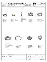
1 Hex Head Bolt, 5/8-11 x 1” Stainless Steel 1 1 1
2 Operating Nut, 2” Square Ductile Iron 1 1 1
3 O-ring Rubber 2 2 2
5 Stufng Box Gasket Rubber O-ring 1 1 1
6 Hex Head Bolt, 5/8-11 x 1-3/4” Stainless Steel 2 2 2
7 Stufng Box Ductile Iron 1 1 1
8 Bonnet Ductile Iron 1 1 1
9 Hex Head Bolt, 5/8-11 x 2” Stainless Steel 4 - -
10 Bonnet Gasket Rubber 1 1 1
11 Body Ductile Iron 1 1 1
12 Stem
Bronze
1 1 1
Stainless Steel (Optional)
13 Wedge Nut Bronze 1 1 1
14 Resilient Wedge
Ductile Iron,
Encapsulated with
EPDM Rubber
1 1 1
15 Hex Nut, 5/8-11 Stainless Steel 6 8 10
19 Hex Head Bolt, 5/8-11 x 2-1/4” Stainless Steel - 6 -
21 Hex Head Bolt, 5/8-11 x 2-1/2” Stainless Steel - - 8
40 UL/FM Label Film 1 1 1
45 Pipe Plug, 3/8 NPT Stainless Steel 1 1 1
49 O-ring Rubber 1 1 1
65 Upper Thrust Washer Stainless Steel 2 2 2
69 Wedge Cover Polymer 2 2 2
SERIES 2500 - TAPPING VALVE PARTS LIST, 4”–8” SIZES

AMERICAN Flow Control Page 5A-13
Tapping Valves
Ref
No.
Description Material
Qty.
Series 2500-1
10” 12”
1 Hex Head Bolt, 5/8-11 x 1” Stainless Steel 1 1
2 Operating Nut, 2” Square Ductile Iron 1 1
3 O-ring Rubber 2 2
5 Stufng Box Gasket Rubber O-ring 1 1
7 Stufng Box Ductile Iron 1 1
8 Bonnet Ductile Iron 1 1
9 Hex Head Bolt, 5/8-11 x 2” Stainless Steel 4 4
10 Bonnet Gasket Rubber 1 1
11 Body Ductile Iron 1 1
12 Stem
Bronze
1 1
Stainless Steel (Optional)
13 Wedge Nut Bronze 1 1
14 Resilient Wedge
Ductile Iron,
Encapsulated with
EPDM Rubber
1 1
15 Hex Nut, 5/8-11 Stainless Steel 14 4
22 Hex Head Bolt, 5/8-11 x 2-3/4” Stainless Steel 10 -
40 UL/FM Label Film 1 1
45 Pipe Plug, 3/8 NPT Stainless Steel 1 1
48 Hex Nut, 3/4-10 Stainless Steel - 10
49 O-ring Rubber 1 1
65 Upper Thrust Washer Stainless Steel 2 2
67 Hex Head Bolt, 3/4-10 x 3” Stainless Steel - 10
69 Wedge Cover Polymer 2 2
SERIES 2500 - TAPPING VALVE PARTS LIST, 10” & 12” SIZES

AMERICAN Flow Control Page 5A-14
Tapping Valves
SERIES 2500 - TAPPING VALVE PARTS LIST, 14”–24” SIZES
Ref
No.
Description Material
Qty.
Series 2500
14” 16” 18” 20” 24”
1 Hex Head Bolt, 5/8-11 x 1-3/4” Stainless Steel 1 1 1 1 1
2
Operating Nut,
2” Square
Ductile Iron 1 1 1 1 1
3 O-ring Rubber 2 2 2 2 2
4 Upper Thrust Washer Delrin 1 1 1 1 1
5 Stufng Box Gasket Rubber O-ring 1 1 1 1 1
6 O-ring Rubber 1 1 1 1 1
7 Stufng Box Ductile Iron 1 1 1 1 1
8 Bonnet Ductile Iron 1 1 1 1 1
9 Hex Head Bolt, 7/8-9 x 3” Stainless Steel 4 4 4 - -
9 Hex Head Bolt, 7/8-9 x 4” Stainless Steel - - - 4 4
10 Bonnet Gasket Rubber 1 1 1 1 1
11 Body Ductile Iron 1 1 1 1 1
12 Stem
Bronze
1 1 1 1 1
Stainless Steel
(Optional)
13 Wedge Nut Bronze 1 1 1 1 1
14 Resilient Wedge
Ductile Iron,
Coated with
EPDM Rubber
1 1 1 1 1
15 Wedge Cover Polymer 2 2 2 2 2
16 Wedge Cover Pin Polymer 2 4 4 2 2
17 Hex Head Bolt, 3/4-10 x 3-1/2” Stainless Steel 14 16 - - -
17 Hex Head Bolt, 7/8-9 x 4” Stainless Steel - - 16 - -
17 Hex Head Bolt, 7/8-9 x 4-1/2” Stainless Steel - - - 18 -
17 Hex Head Bolt, 7/8-9 x 5” Stainless Steel - - - - 20
18 Hex Nut, 3/4-10 Stainless Steel 14 16 - - -
18 Hex Nut, 7/8-9 Stainless Steel - - 16 18 20
19 Hex Nut, 7/8-9 Stainless Steel 4 4 4 4 4
20 Pipe Plug, 3/8 NPT Stainless Steel 1 1 1 1
21 Lower Thrust Washer Delrin 1 1 1 1 1

AMERICAN Flow Control Page 5A-15
Tapping Valves
Ref
No.
Description Material
Qty.
Series 2500
14” 16” 18”
1-K
Key
8 mm x 7 mm x 40 mm
Steel 1 1 1
2-K
Operating Nut,
2” Square
Ductile Iron 1 1 1
3 O-ring Rubber 2 2 2
4 Upper Thrust Washer Delrin 1 1 1
5 Stufng Box Gasket Rubber O-ring 1 1 1
6 O-ring Rubber 1 1 1
7 Stufng Box Ductile Iron 1 1 1
8 Bonnet Ductile Iron 1 1 1
9 Hex Head Bolt, 7/8-9 x 3” Stainless Steel 4 4 4
10 Bonnet Gasket Rubber 1 1 1
11 Body Ductile Iron 1 1 1
12 Stem
Bronze
1 1 1
Stainless Steel
(Optional)
13 Wedge Nut Bronze 1 1 1
14 Resilient Wedge
Ductile Iron,
Coated with
EPDM Rubber
1 1 1
15 Wedge Cover Polymer 2 2 2
16 Wedge Cover Pin Polymer 2 4 4
17
Hex Head Bolt,
3/4-10 x 3-1/2”
Stainless Steel 14 16 -
17
Hex Head Bolt,
7/8-9 x 4”
Stainless Steel - - 16
18 Hex Nut, 3/4-10 Stainless Steel 14 16 -
18 Hex Nut, 7/8-9 Stainless Steel - - 16
19 Hex Nut, 7/8-9 Stainless Steel 4 4 4
20 Pipe Plug, 3/8 NPT Stainless Steel 1 1 1
21 Lower Thrust Washer Delrin 1 1 1
22 Stud, 5/8-11 x 2-3/4” Stainless Steel 4 4 4
23 Hex Nut, 5/8-11 Stainless Steel 4 4 4
25
Square Key,
5/16 x 2-1/2
Hardened Steel 1 1 1
27
Bevel Gear Operator
2:1
Rotork IB5 1 1 1
29 Actuator Gasket Rubber O-ring 1 1 1
30
Hex Head Bolt,
3/8-16 x 3/4”
Zinc Plated Steel 1 1 1
31 Washer Steel 1 1 1
60-K
Spring Pin,
1/4 x 3/4”
Stainless Steel 1 1 1
SERIES 2500 - TAPPING VALVE W/BEVEL GEARING PARTS LIST, 14”–18” SIZES

AMERICAN Flow Control Page 5A-16
Tapping Valves
SERIES 2500 - TAPPING VALVE W/BEVEL GEARING PARTS LIST, 20” & 24” SIZES
Ref
No.
Description Material
Qty.
Series 2500
20” 24”
1-K
Key
8 mm x 7 mm x 40 mm
Steel 1 1
2-K
Operating Nut,
2” Square
Ductile Iron 1 1
3 O-ring Rubber 2 2
4 Upper Thrust Washer Delrin 1 1
5 Stufng Box Gasket Rubber O-ring 1 1
6 O-ring Rubber 1 1
7 Stufng Box Ductile Iron 1 1
8 Bonnet Ductile Iron 1 1
10 Bonnet Gasket Rubber 1 1
11 Body Ductile Iron 1 1
12 Stem
Bronze
1 1
Stainless Steel
(Optional)
13 Wedge Nut Bronze 1 1
14 Resilient Wedge
Ductile Iron,
Coated with
EPDM Rubber
1 1
15 Wedge Cover Polymer 2 2
16 Wedge Cover Pin Polymer 2 2
17
Hex Head Bolt,
7/8-9 x 4-1/2”
Stainless Steel 18 -
17
Hex Head Bolt,
7/8-9 x 5”
Stainless Steel - 20
18 Hex Nut, 7/8-9 Stainless Steel 18 20
20 Pipe Plug, 3/8 NPT Stainless Steel 1 1
21 Lower Thrust Washer Delrin 1 1
22 Stud, 7/8-9 x 3-1/2” Stainless Steel 4 4
23 Hex Nut, 7/8-9 Stainless Steel 4 4
25
Square Key,
1/2 x 2-3/4
Hardened Steel 1 1
27
Bevel Gear Operator
3:1
Rotork IB7 1 1
28
Socket Head Cap Screw
3/4-10 x 2”
Stainless Steel 4 4
29 Actuator Gasket Rubber O-ring 1 1
30
Hex Head Bolt,
1/2-13 x 1”
Zinc Plated Steel 1 1
31 Washer Steel 1 1
60-K
Spring Pin,
1/4 x 3/4”
Stainless Steel 1 1

AMERICAN Flow Control
Page 5A-17
Tapping Valves
SERIES 2500 - TAPPING VALVE W/BEVEL GEARING PARTS LIST, 30” & 36” SIZES
Ref
No.
Description Material
Qty.
Series 2500
30” 36”
1-K
Key
8 mm x 7 mm x 40 mm
Steel 1 1
2-K
Operating Nut,
2” Square
Ductile Iron 1 1
3 O-ring Rubber 2 2
4 Upper Thrust Washer Delrin 1 1
5 Stufng Box Gasket Rubber O-ring 1 1
6 O-ring Rubber 1 1
7 Stufng Box Ductile Iron 1 1
8 Bonnet Ductile Iron 1 1
10 Bonnet Gasket Rubber 1 -
10 Bonnet Gasket EPDM Rubber - 1
11 Body Ductile Iron 1 1
12 Stem
Bronze
1 1
Stainless Steel
(Optional)
13 Wedge Nut Bronze 1 1
14 Resilient Wedge
Ductile Iron,
Coated with
EPDM Rubber
1 1
15 Wedge Cover Polymer 2 2
16 Wedge Cover Pin Polymer 2 2
17
Hex Head Bolt,
1”-8 x 6”
Stainless Steel 24 -
17
Hex Head Bolt,
1-1/4-7 x 7”
Stainless Steel - 28
18 Hex Nut, 1”-8 Stainless Steel 24 -
18 Hex Nut, 1-1/4-7 Stainless Steel - 28
20 Pipe Plug, 3/8 NPT Stainless Steel 4 4
21 Lower Thrust Washer Delrin 1 1
22 Stud, 1”-8 x 6” Stainless Steel 6 -
22 Stud, 1”-8 x 6-1/2” Stainless Steel - 8
23 Hex Nut, 1”-8 Stainless Steel 12 16
25
Square Key,
1/2 x 3-1/2
Hardened Steel 1 -
25
Square Key,
5/8 x 4”
Hardened Steel - 1
27
Bevel Gear Operator
4:1
Rotork IB8 1 -
27
Bevel Gear Operator
4:1
Rotork IB10 - 1
28
Socket Head Cap Screw
3/4-10 x 2”
Stainless Steel 4 -
28
Socket Head Cap Screw
5/8-11 x 2”
Stainless Steel - 8
29 Actuator Gasket Rubber O-ring 1 1
30
Hex Head Bolt,
3/4-10 x 1”
Zinc Plated Steel 1 1
31 Washer Steel 1 1
60-K
Spring Pin,
1/4 x 3/4”
Stainless Steel 1 1

AMERICAN Flow Control Page 5A-18
Tapping Valves
Ref
No.
Description Material
Qty.
Series 2500
42” 48”
1-K
Key
14 mm x 9 mm x 54 mm
Steel 1 1
2-K
Operating Nut,
2” Square
Ductile Iron 1 1
3 O-ring Rubber 2 2
4 Upper Thrust Washer Delrin 1 1
5 Stufng Box Gasket Rubber O-ring 1 1
6 O-ring Rubber 1 1
7 Stufng Box Ductile Iron 1 1
8 Bonnet Ductile Iron 1 1
10 Bonnet Gasket EPDM Rubber 1 1
11 Body Ductile Iron 1 1
12 Stem
Bronze
1 1
Stainless Steel
(Optional)
12 Stem Stainless Steel - -
13 Wedge Nut Bronze 1 1
14 Resilient Wedge
Ductile Iron,
Coated with
EPDM Rubber
1 1
15 Wedge Cover Polymer 2 2
16 Wedge Cover Pin Polymer 2 2
17
Hex Head Bolt,
1-1/4-7 x 7-1/2”
Stainless Steel 32 -
17
Hex Head Bolt,
1-3/8-6 x 8-1/2”
Stainless Steel - 36
18 Hex Nut, 1-1/4-7 Stainless Steel 32 -
18 Hex Nut, 1-3/8-6 Stainless Steel - 36
20 Pipe Plug, 1/2 NPT Stainless Steel 4 4
21 Lower Thrust Washer Delrin 1 1
22 Stud, 1-1/4-7 x 7-1/2” Stainless Steel 8 -
22 Stud, 1-1/4-7 x 7-3/4” Stainless Steel - 8
23 Hex Nut, 1-1/4-7 Stainless Steel 16 16
25
Square Key,
3/4 x 4-1/2
Hardened Steel 1 1
27
Bevel Gear Operator
8:1
Rotork IB12 1 1
28
Socket Head Cap Screw
3/4-10 x 2-1/2”
Stainless Steel 8 8
29 Actuator Gasket Rubber O-ring 1 1
30
Hex Head Bolt,
7/8-9 x 1-1/2”
Zinc Plated Steel 1 1
31 Washer Steel 1 1
50-K
Set Screw
5/16-18 x 3/4”
Stainless Steel 1 1
SERIES 2500 - TAPPING VALVE W/BEVEL GEARING PARTS LIST, 42” & 48” SIZES

AMERICAN Flow Control Page 5A-19
Tapping Valves
2500 TAPPING VALVE SPECIFICATIONS
Tapping valves shall be resilient wedge type with bodies and bonnets made of ductile iron for 250 psig
working pressure.
The alignment ring dimensions of the tapping valve ange conform to MSS SP 60 to help ensure true
alignment of the valve with the tapping sleeve. The outlet end of the valve shall have the desired joint
connection for the intended pipe.
All tapping valves shall include a minimum 3/8 in. NPT pipe plug on the bonnet of the valve body to aid in the
eld testing of the valve.
All wedges shall be fully encapsulated with EPDM rubber.
All wedges shall be provided with guide covers.
All interior and exterior ferrous surfaces shall be protected against corrosion by fusion-bonded epoxy coating.
The coating shall be applied prior to assembly to assure coverage of all exposed areas, including bolt holes.
Tapping valve shall be AMERICAN Flow Control’s 4 in.–48 in. Series 2500 Ductile Iron 250 psig rating
(accepts full size shell cutter).
●
●
●
●
●
●
/