Page is loading ...


GUIDE TO INSTALLATION AND OPERATION
ENC-291p
Radio Frequency Interference and Immunity
This unit generates, uses, and can radiate radio frequency
energy. If the unit is not properly installed and used in
accordance with this guide, it may cause interference with radio
communications. Operation with non-certified peripheral devices
is likely to result in interference with radio and television
reception. This equipment has been tested and complies with
the limits in accordance with the specifications in:
FCC Part 15, Subpart B
CE EN50081-1:1992
CE EN50082-1:1992.
CONTACT MIRANDA
For technical assistance, please contact the Miranda Technical
Support centre nearest you:
Americas
Telephone:
+1-800-224-7882
e-mail:
Asia
Telephone:
+81-3-5730-2987
e-mail:
Europe, Middle East, Africa, UK
Telephone:
+44 (0) 1491 820222
e-mail:
France (only)
Telephone:
+33 (0) 1 55 86 87 88
e-mail:
Visit our web site at www.miranda.com

GUIDE TO INSTALLATION AND OPERATION
ENC-291p
CONTENTS
page
1.0 ENC-291p SDI to NTSC/PAL Encoder.......1
1.1 Introduction ………………………............. 1
1.2 Features .........................................…….. 1
2.0 Physical Layout ………………............. 2
3.0 Installation .......................................... 3
3.1 Power Supply .......................................... 3
3.2 SDI Input ……..…………….................... 3
3.3 Composite Output ……….……............... 3
4.0 Operation ............................................ 4
4.1 Switch Settings ....................................... 4
4.2 Status LED ………………………............... 5
5.0 Specifications ................………..……. 6

GUIDE TO INSTALLATION AND OPERATION
ENC-291p

GUIDE TO INSTALLATION AND OPERATION
ENC-291p | 1
1.0 ENC-291p 12-bit SDI to NTSC/PAL Encoder
1.1 Introduction
The ENC-291p is the industry’s smallest composite encoder.
This product automatically detects 525-line and 625-line SDI
signals conforming to the SMPTE 259M-C standard and
provides a NTSC, PAL, PAL-M, or PAL-N composite output
signal. An internal test pattern generator provides a color bars
test signal. This feature-packed unit delivers ease-of-use, a
simplified design, easy installation and operation.
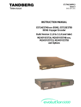
Figure 1: ENC-291p functional block diagram
1.2 Features
• Automatic 525-line and 625-line format input detection
• NTSC or PAL-M composite output for 525-line input and PAL
or PAL-N composite output for 625-line input
• Y-only (monochrome) output selection
• Output setup selection: 7.5 or 0 IRE
• Color bars generator
• Bi-color LED providing error status on input SDI signal
• Very small packaging with aluminum extruded body
Serial to
parallel
SDI IN
COMPOSITE
OUT
Encoder

GUIDE TO INSTALLATION AND OPERATION
2 | ENC-291p
2.0 Physical Layout
Figure 2 illustrates the ENC-291p’s major parts and their
locations. The video source is connected to the SDI input BNC
and the encoded signal is provided by the composite output.
Error status is provided by the status LED and mode settings are
configured by two 3-position slide switches. Finally, the power
source is connected to the power connector.
Figure 2: Overall view of the ENC-291p
SDI input
Power connector
Composite output
Status LED
3-position slide switches

GUIDE TO INSTALLATION AND OPERATION
ENC-291p | 3
3.0 Installation
3.1 Power Supply
The LKS-WSU power supply is used to power the ENC-291p for
both 110V and 220V operation. This power supply provides a
regulated +5 VDC@1A power source over an input range of 90 –
260 VAC. The ENC-291p employs a mini XLR-3 connector for its
power needs. Figure 3 provides a detailed pinout of the male
connector.
13
2
(male connector-facing)
Pin 1: Shield
Pin 2: GND
Pin 3: +5 VDC
Figure 3: Power connector pinout
3.2 SDI Input
Connect an SDI serial digital signal to the BNC labeled SDI IN.
The SDI input signal must conform to the SMPTE 259M-C
standard.
3.3 Composite Output
A composite signal conforming to the SMPTE 170M or ITU-R
BT.470-6 standard is provided at the composite output BNC.

GUIDE TO INSTALLATION AND OPERATION
4 | ENC-291p
4.0 Operation
4.1 Switch Settings
Figure 4 shows the location of the slide switches and the status
LED.
Output setup and format (SW1)
Normal, Y only and Test (SW2)
picoLink
COMPOSITE
OUT
SDI IN
Status LED
7.5 IRE
0 IRE
Alt. Out
Normal
Y Only
Test
ENC-291p
Miranda Technologies inc.
Made in Canada
Figure 4: ENC-291p slide switch and LED locations
Output setup and format switch (SW1)
7.5 IRE: To add a 7.5 IRE setup to the output NTSC
composite signal, set SW1 to this position. There is
no setup for PAL, PAL-M, and PAL-N output signals.
0 IRE: For no setup on the output composite signal, set
SW1 to this position.
Alt. Out: To enable PAL-M and PAL-N outputs during 525-
line and 625-line input formats respectively, set SW1
to this position. Refer to Table 1 for the output
format provided during this setting.

GUIDE TO INSTALLATION AND OPERATION
ENC-291p | 5
4:2:2 input Output
SW1=7.5 IRE
or 0 IRE
SW1=Alt. Out
525-lines
NTSC PAL-M
625-lines
PAL PAL-N
Table 1: Output format conversion
Normal, Y-only, and test pattern switch (SW2)
Normal: For normal operation, set SW2 to this position.
Y-Only: Setting SW2 to this position provides a monochrome
output signal by forcing the output chroma to 0.
Test: Set SW2 to Test in order to enable the test pattern
generator. Make sure a valid SDI input signal is
installed. For all output formats, the test signal is
75% color bars with 100% white bar.
4.2 Status LED
The color of the status LED, located on top near the Miranda
logo, identifies the presence of input errors and the selection of
the test pattern. Possible indications are:
Green: Indicates the ENC-291p is powered and has
detected a valid SDI serial digital signal at its input.
Red: Indicates that the input is in error:
• no input signal has been detected
• an invalid input signal has been detected.
Orange: The test pattern is selected.
If an input signal error is detected while the test pattern is
enabled, the status LED will turn and remain red.

GUIDE TO INSTALLATION AND OPERATION
6 | ENC-291p
5.0 Specifications
Input
Signal: SMPTE 259M-C (270 Mbps)
Cable length: 300 m (985') Belden 8281
Return loss: > 15 dB up to 270 MHz
Connector: 75 Ω BNC
Output
Signal: NTSC-M (525/60) SMPTE 170M or
PAL (625/50) ITU-R BT.470-6
PAL-M (525/60) ITU-R BT.470-6
PAL-N (625/50) ITU-R BT.470-6
Return loss: > 35 dB up to 5 MHz
Connector: 75 Ω BNC
Processing performance
Signal path: 10 bits
Quantization: 12 bits
Sampling: 216 MHz (16X oversampling)
Freq. response: ±0.5 dB to 5 MHz
Processing delay: 3.2 us
Test signal: 75% color bars with 100% white
Electrical
Voltage requirement: +5 VDC
Power consumption: 1.2 W (typical)
Power connector: Mini XLR-3
Mechanical
Overall size: 102 mm x 25 mm x 18 mm
(4” x 1” x 0.7”)
Power cable length: 127 mm (5”)
Full spec. temp. range: 0°C (32°F) to 30°C (86°F)
/