Eaton COOPER POWER SERIES Installation guide

Type
Installation guide

This manual is also suitable for

Eaton COOPER POWER SERIES insulated protective caps provide a safe and reliable solution for protecting energized 15 and 25 kV class deadbreak interfaces. With its fully shielded submersible protection, this cap meets IEEE Std 386™-2006 standards and offers easy installation without special tools. The semiconducting EPDM shield maintains ground potential, preventing low-energy discharge, and the peroxide-cured EPDM insulation ensures durability. Trust Eaton COOPER POWER SERIES caps for temporary or permanent installation on bushings, junctions, and other accessories.

Eaton COOPER POWER SERIES insulated protective caps provide a safe and reliable solution for protecting energized 15 and 25 kV class deadbreak interfaces. With its fully shielded submersible protection, this cap meets IEEE Std 386™-2006 standards and offers easy installation without special tools. The semiconducting EPDM shield maintains ground potential, preventing low-energy discharge, and the peroxide-cured EPDM insulation ensures durability. Trust Eaton COOPER POWER SERIES caps for temporary or permanent installation on bushings, junctions, and other accessories.

600 A 15/25 kV class insulated
protective cap
Description
Eaton meets the full requirements of IEEE Std
386™-2006 standard – Separable Insulated
Connector Systems, and provides insulated, fully
shielded submersible protection for energized
15 and 25 kV class deadbreak interfaces with
its Cooper Power™ series 600 A, 15/25 kV class
insulated protective cap. The cap is required
for temporary or permanent installation on
15/25kV deadbreak bushings, junctions and other
accessories having interfaces that conform to IEEE
Std 386™-2006 standard.
The cap design includes a semiconducting EPDM
insert for stress relief and high quality peroxide
cured EPDM insulation. The molded EPDM semi-
conducting shield maintains ground potential
on the cap’s surface when the drain wire is
connected to a common ground.
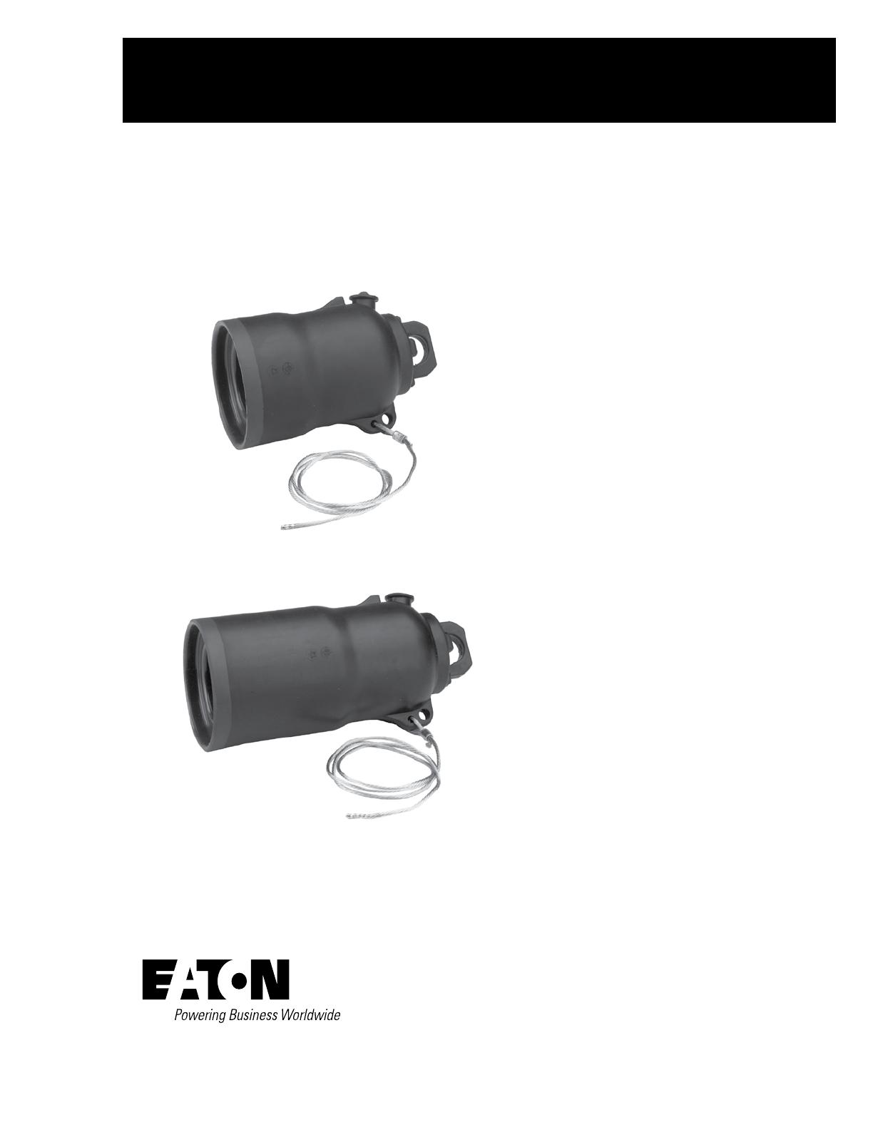
(Top image on left shows standard insulated
protective cap. Bottom image shows U-OP™/
T-OP™ II connector insulated protective cap.)
Installation
No special tools are required. A hotstick tool is
used to place the protective cap on a de-energized
bushing. Refer to Service Literature S600-63-1
15, 25, and 35 kV Protective Cap Installation
Instructions for further information.
Production tests
Tests are conducted in accordance with IEEE Std
386™-2006 standard.
ac 60 Hz 1 Minute Withstand
40 kV
Minimum Corona Voltage Level
19 kV
Tests are conducted in accordance with Eaton
requirements.
Physical Inspection
Periodic Dissection
Periodic Fluoroscopic Analysis
Deadbreak Connectors
Catalog Data
CA650 060EN
Effective May 2015
Supersedes 600-43 June 1997
COOPER POWER
SERIES
Figure 1. Cutaway illustration of standard cap with drain wire shows design detail and dimensions.
ote:N Dimensions given are for reference only.
PULLING EYE
Stainless Steel Reinforced
Pulling Eye ensures high
strength for hotstick opera-
tion.
DRAIN WIRE AND
GROUNDING EYE
30-inch, #14 AWG Stranded Tin
Plated Copper Drain Wire prevents
low energy discharge from the
molded semi-conducting shield.
EPDM INSULATION
High Quality Peroxide Cured
EPDM Insulation is mixed and
formulated in-house for
complete control of raw rubber
characteristics.
SEMI-CONDUCTIVE SHIELD
Molded Semi-Conductive
EPDM Shield meets requirements
of IEEE Std 592™-2007 standard.
5/8" – 11 UNC
2A BRASS
THREAD
3.25"
(83 mm)
5.8"
(147 mm)
Table 1. Voltage Ratings and Characteristics
Description kV
Standard Voltage Class 25
Maximum Rating Phase-to-Ground 15.2
ac 60 Hz 1 Minute Withstand 40
dc 15 Minute Withstand 78
BIL and Full Wave Crest 125
Minimum Corona Voltage Level 19
Voltage ratings and characteristics are in accordance with IEEE Std 386™-2006 standard.
2
Catalog Data CA650060EN
Effective May 2015
600 A 15 kV and 25 kV class insulated protective cap
www.eaton.com/cooperpowerseries
Ordering information
To order a 15 and 25 kV class insulated protective cap kit, refer to
Table 2.
Each kit contains:
Protective Cap
Silicone Lubricant
Installation Instruction Sheet
Figure 2. Cutaway illustration of T-OP™ II connector cap with drain wire shows design detail and dimensions.
ote:N Dimensions given are for reference only.
Table 2. Insulated Protective Cap Kits
Description Catalog Number
Standard Cap with drain wire (See Figure 1) with permanent
studs
DPC625
U-OP/T-OP II Connector Cap with drain wire (See Figure 2)
without stud
DPC625UT
SEMI-CONDUCTIVE SHIELD
Molded Semi-Conductive EPDM
Shield meets requirements of
IEEE Std 592™-2007 standard.
7.6"
(194 mm)
3.25"
(83 mm)
PULLING EYE
Stainless Steel Pulling Eye
ensures high strength for
hotstick operation.
DRAIN WIRE AND
GROUNDING EYE
30-inch, #14 AWG Stranded Tin
Plated Copper Drain Wire prevents
low energy discharge from the
molded semi conducting shield.
EPDM INSULATION
High Quality Peroxide Cured EPDM
Insulation is mixed and formulated
in-house for complete control of raw
rubber characteristics.
5/8"-11 UNC 2A THREADED
ALUMINUM INSERT allows cap to
be installed on bushing using either
a standard 600 A stud, the
extended stud used with T-OP II
connector or the U-OP stud.
3
Catalog Data CA650060EN
Effective May 2015
600 A 15 kV and 25 kV class insulated protective cap
www.eaton.com/cooperpowerseries
Eaton, Cooper Power, U-OP, and T-OP are
valuable trademarks of Eaton in the U.S. and
other countries. You are not permitted to use
these trademarks without the prior written
consent of Eaton.
IEEE Std 386™-2006 and IEEE Std 592™-
2007 standards are trademarks of Institute
of Electrical and Electronics Engineers,
Inc., (IEEE). This publication/product is not
endorsed or approved by the IEEE.
600 A 15 and 25 kV class insulated protective capCatalog Data CA650060EN
Effective May 2015
Eaton
1000 Eaton Boulevard
Cleveland, OH 44122
United States
Eaton.com
Eaton’s Cooper Power Systems Division
2300 Badger Drive
Waukesha, WI 53188
United States
Eaton.com/cooperpowerseries
© 2015 Eaton
All Rights Reserved
Printed in USA
Publication No. CA650060EN
For Eaton's Cooper Power series insulated
protective cap product information
call 1-877-277-4636 or visit:
www.eaton.com/cooperpowerseries.
  • Page 1 1
  • Page 2 2
  • Page 3 3
  • Page 4 4

Eaton COOPER POWER SERIES Installation guide

Type
Installation guide
This manual is also suitable for

Eaton COOPER POWER SERIES insulated protective caps provide a safe and reliable solution for protecting energized 15 and 25 kV class deadbreak interfaces. With its fully shielded submersible protection, this cap meets IEEE Std 386™-2006 standards and offers easy installation without special tools. The semiconducting EPDM shield maintains ground potential, preventing low-energy discharge, and the peroxide-cured EPDM insulation ensures durability. Trust Eaton COOPER POWER SERIES caps for temporary or permanent installation on bushings, junctions, and other accessories.

Ask a question and I''ll find the answer in the document

Finding information in a document is now easier with AI