Page is loading ...

Installation Instructions
Model 6128 A-Series
Electronic Safe Lock
• FürAnweisungenaufDeutschbesuchenSiebittediefolgendeWebsite:
• Paraobtenerinstruccionesenespañol,visitelasiguientepáginaweb:
• Pourobtenirlesinstructionsenfrançais,veuillezconsulterlesiteci-dessous:
• Peristruzioniinlinguaitaliana,visitareilsitowebseguente:
• ForinstructionsontheChineseversion,pleasevisitthefollowingURL:
Mounting Considerations
• Sargent&Greenleaf6100seriesMotorizedElectronicCombinationLockshave
beendesignedtousethesamemountingscrewlocationsandoccupythesame
spaceasmostotherS&Glocks,bothmechanicalandelectronic.
• Modicationstothelock(includinglockboltattachments)arenotrecommended,
andwillvoidtheyourwarranty.
• Aminimumdistanceof.150”(3,8mm)isrequiredbetweentheendofthelockcasecontainingthebolt
andtheclosestapproachofthesafe’sblockingbarorcamplatewhichisnormallyblockedbytheextended
lockbolt.Donotallowthesafe’sblockingbarorcamplatetodepresstheelectroniclock’sboltfartherthanit
retractsduringnormalmotoroperation.iscanleadtoinconsistentlockoperation.
• e6100seriesrequirestwo9-voltalkalinebatteries(mayormaynotbeincludedwithyourlockdepending
onthespecickitordered).WerecommendDuracell®batteries.Donotuseoldorpartiallydrainedbatteries.
Attaching Screws: Useonlythescrewsprovidedwiththelock.Lockbodymountingscrewswillbe
either¼-20orM6,dependingontheapplication.eymustengagethemountingplatebyatleastfour
fullthreads.Donotuselockwashersorthreadsealingcompoundsunlessspecicallydirectedtodoso
inthefullinstallationinstructions
Recommended Attaching Screw Torque: 30to40inch-pounds(3.4to4.5Nm)forthelockbody.No
morethan15inch-pounds(1.695Nm)forthekeypadattachingscrews.
Minimum Lock Cable (Spindle) Hole Diameter: 0.312”(7,9mm)MaximumLockCable(Spindle)
HoleDiameter:0.406”(10,3mm)LockisDesignedtoMove:0.0lbs.(0Newtons)
Lock Bolt Maximum Free Movement: 0.352”(8,95mm)Atleast0.109”(2,77mm)ofthelockbolt
remainsoutsidetheedgeofthelockcasewhenboltisfullyretracted.
Maximum Bolt End Pressure:Lockisdesignedtowithstandatleast225lbs.(1000Newtons)
MaximumBoltSidePressure:Safeandcontainerboltworkorlockingcamdesignsmustneverapply
morethan225lbs.(1000Newtons)ofsidepressureonthelockbolt.
Interface with Boltwork:islockisnotintendedfordirectboltworkattachment.Beforeinstalling
thelock,operatethesafeopeningmechanismandverifythattheinstalledpositionwilleectively
securetheboltworkswhenthelockislocked.Aerinstallation,checkthatthereiaclearancebetween
thecombinationlockboltandtheboltworks;aspressureontheboltcouldaectthelock’sabilityto
functionproperly.
Mounting Environment:elockbodyisdesignedtobemountedinsideasecurecontainer.e
containermustbeconstructedtooerprotectionagainstphysicalattackdirectedatthelock.e
amountofprotectionisdependentonthedesiredlevelofsecurityforthesystemasawhole.Lock
protectionmayincludebarriermaterials,relockdevices,thermalbarriers,thermalthese.Relockdevice
attachingscrewsmustNOTbelongerthanthedepthofthetappedattachingscrewholeprovidedin
thelockcase.Aminimumdistanceof.150inch(3,8mm)isrecommendedbetweentheendofthelock
caseandtheclosestapproachofthesafe’sblockingbarorcamplate(whichisnormallyblockedbythe
extendedlockbolt).Maintainingthisclearancewillallowthelocktodeliveroptimumperfor-mance.
econtainershouldbeconstructedtopreventaccesstothecombinationlockwithouttheuseoftools
whenthecontainerdoorordrawerisleopen.
Code Restrictions:Personaldatathatcanberelatedtoacodeholder,suchasabirthdate,streetnumber,orphonenumber,shouldnot
beusedincreatingalockcode.Avoidcodesthatcanbeeasilyguessed.
Note: Everyinstallationofthisproductmustcomplywiththeserequirementsandthoseintheproductinstallationinstructionsto
qualifyforthemanufacturer’swarrantyandtocomplywithEN1300requirements.
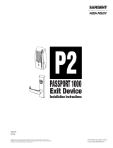
3.320"(84,3mm)
2.624"(66,6mm)
1.624"(41,2mm)
1.000"(25,4mm)
Bolt extension:
Locked=.461"
(11,71mm)
Unlocked=.125"
(3,18mm)
2.400"(61,0mm)
.312"
7,9mm
.281"
7,1mm
1.165"(30mm)

Before You Install
Your6128A-SeriesLockwasmostlikelyshippedwiththekeypadandkeypadextensionconnectedtothelock
cablestoallowforpre-installationtesting.Ifyourlockdoesnothavecablesalreadyconnectedtothekeypad
andkeypadextension,temporarilyconnectthemnowasshownintheseinstructions.Youshouldinstallfresh
batteriesinthekeypad(S&GrecommendsDuracell®alkalinebatteries)andcheckthefunctionofthelockprior
toinstallationbypressing10101010#andobservingthelockboltretract,thenextend6secondslater.Aer
thischeck,disconnectthecablesfromtheextensionbaseandkeypadbypullingontheconnectors(NOTon
thecablesthemselves).einstallershouldwearaproperlygroundedESDwriststrapwhileworkingwithlock
cablesandcomponentstoavoidESDdamage.
1. Removetheexistinglock(ifpresent).emountingplateshouldbesmoothand
at,with¼-20(M6)mountingscrewholes.ewirechannel(spindlehole)must
haveadiameterofatleast0.312inch(7,9mm).e6100seriescanbemounted
right-hand,le-hand,vertical-up,orvertical-downwithoutanymodicationsor
adjustments.
2. Useareamerorroundletoremoveanysharpedgesfromthewirechannel(spindle
hole)thatmightdamagethewirecable.Gentlypulltheconnectorstoeasethecables
throughthehole.Pull6”to8”(15to20cm)ofcabletothefrontofthesafedoor.
Laterintheinstallation,excesskeypadextensioncablewillbepulledbackinsidethe
safedoor.Makesurecablesarenotcrimpedorstressedatanypoint.
3. Usingtwoofthe¼-20(orM6)screwsinthekit,looselyattachthelockbodytothe
safe’smountingplate.isisjusttoholditinplaceduringcableattachmentstothe
keypadandkeypadextension.Beverycarefultoavoidcrushingorcrimpingthe
cables.Notetheblack/red/greenwirebundle.isisfortheboltpositionindicator,
adrycontactswitch(200VDC,0.5ampmax.)eblackwireiscommon,thegreen
wirecompletesacircuittotheblackwirewhenthelockboltisretracted,andthered
wirecompletesacircuittotheblackwirewhenthelockboltisextended.eBPI
canbeusedtotriggeranyswitch-activateddevice.
Notethebluewireloop.isisthesecureloop,aclosedcircuitthatmaybeusedin
applicationsrequiringswitchesorotherdevicestosignalthelockthatboltworkis
thrown,thedoorisclosed,orsomeotheractionhastakenplace.elockboltwill
NOTretractifthecircuitformedbythebluewireloopisopen.Bothsetsofwires
shouldbebundledandplacedwheretheywillnotinterferewithmovingboltwork
componentsifnotused.
4. Removethelockmountingscrewssoyoucancarefullypulltheexcessextension
basecableinside.Itisimportanttomakesurethekeypadandextensioncablesare
withintherecessedchannelsunderneaththelockcasebeforethecaseissecurely
attachedbythethreemountingscrews.Onceplacedinthemostconvenientchannel,
eachcableshouldbeprotectedunderneaththecasebyaself-adhesivefoamorvinyl
pad.Itisveryimportantthatcablesarenotfolded,crimped,orcrushedbeneaththe
lockcase.erearefoursetsofwiresthatmustbecarefullyplacedwheretheywill
notinterferewithorbedamagedbymovingboltwork.eseare:
• excesskeypadcable(4-conductor)
• secureloop(1-conductorbluewire)
• boltpositionindicator(BPI)wires
• excesskeypadextensioncable(5-conductor)
2

A. Makesurethelockboltdoesn’tbindagainstthesafe’sboltwork.etopphotoshowsbindingoftheedgeof
thecutoutinthesafe’sblockingbar,eventhoughtheboltworkisfullythrowntothelockedposition.Inthe
bottomphoto,thebindinghasbeenrelievedbyremovingasmallamountofmaterialfromthesideofthe
blockingbarcutout.Itisimportantthatthereisclearanceonallsidesofthelock’sboltwhentheboltworkis
inthefullylockedposition.Bindingwillimpairthelock’sperformance.Anynecessarymodicationsshould
bemadetotheboltwork,notthelock.
B. Ifyoursafeincorporatesarelockdevice,youwillneedtoattachtheplatethatnormallyholdsitincheckto
thelockbody.isisusuallydoneatthelock’scoverscrewlocations.Removethecoverscrews.DONOT
REMOVETHELOCKCOVER,asthiswillvoidtheproductwarranty.Typically,thecoverscrewswillbe
replacedwithslightlylonger8-32machinescrews.Yourreplacementscrewsmustengagethethreadedholes
inthelockbodybyatleastfourthreads.Relockdevicedesignsvaryfromsafetosafe.Youmustmakesure
thereplacementcoverscrewsholdthelockcoverrmlyagainstthelockbody,andthattherelockdevice
plateholdsthedevicesecurelyincheck.Otherwise,thereisriskofalockout.Aertheplateisinstalled,once
againchecktomakesurewiresandcablesaresecuredsothattheywillnotcomeintocontactwithmoving
boltworkoranythingelsethatcandamagethem.
Lock installation Considerations
IncorrrectCorrrect
3

Keypad and Keypad Extension Installation with Escutcheon
1. Cleanthefrontsurfaceofthesafedoorsothenumberplatewilladhere.Removetheclearprotective
lmfromthefrontoftheplate,andaxtheincludedserialnumberlabelasshown.Next,remove
theprotectivepaperbackingontheundersideoftheplate,thenrunbothcablesthroughthecenter
holeoftheplate.Placetheplateonthefrontofthesafe,carefullyliningupthemountingscrewholes
inthesafedoor.eplatewillstickinplacewhenpressedagainstthedoor.
2.
3. Placethekeypadbaseoverthekeypadextension,pullallexcesscablethroughthecenterhole(as
shown),lineupthekeypadbasemountingscrewholeswiththoseinthedoor,andusetheincluded
8-32(orM4)machinescrewstosecurelyfastenthemountingbasetothedoor.Itwillalsoholdthe
keypadextensionandnumberplate(ifused)rmlyinplace.eraised,circularpostneartheedge
ofthebasewillbeverynearthebottomofthekeypad.Usethisfeatureasareferencetohelpyou
orientthebasecorrectlybeforeyoufastenitintoplace.
4.
5. Placethekeypadoverthebase.Makesurethekeypadcableisclearofthepad’stwospringclips
asyoupushthekeypadrmlyontothebase.Itshouldsnapintoplace.Ifyouneedtoremovethe
keypad,pullthebottom(areanearesttheS&Glogo)awayfromthemountingbaserst.Neverallow
thekeypadtohangbytheattachedcable.einstallationiscomplete,butdonotclosethesafedoor
untilsuccessfullycompletingthefollowinglocktest.
einstallationiscomplete,butdonotclosethesafedooruntilsuccessfullycompleting
thefollowinglocktest.
efollowingcheckshouldbeperformedthreetimeswiththedoorremainingOPEN.
Atthekeypad,enter10101010#.elockwillBEEPthreetimesanditsboltwillretract.
Turnthesafehandletoverifythatthelockisunlocked.Turnthesafehandletothelocked
position.egreenSTATUS1LEDonthekeypadextensionwilllightbriey.e safe
door should remain open for the three operational checks.Youcanclosethesafedoor
andturnthehandletothelockedpositionaerthethirdoperationalcheck.elockbolt
willextend,andthelockwillBEEPthreetimes.Inaddition,thegreenSTATUS1LEDon
thekeypadextensionwilllightbriey.Testthesafe’shandletomakesureitissecure.
Lock Test
Fromthefrontofthesafe,connecttheve-conductorcable(thelarger
one)tothekeypadextensionbase.econnectorandreceptacleare
“keyed,”sotheconnectorwillonlyseatwhenorientedcorrectly.Route
thecableasshownhere.Makesuretheconnectorisfullyseatedinthe
keypadextensionreceptacle.Notetheself-adhesivepadtotherightofthe
cablereceptacle.Oncetheconnectorispluggedin,removetheprotective
backingfromthispad.Pullallexcesscablethroughthecenteropening
tothefrontoftheextensionbase.enlineupthebase’smountingscrew
holeswiththoseinthedoor,andpresstheextensionagainstthedoor.e
extensioncanbemountedinfourdierentorientations.Picktheonethat
bestsuitsyourparticularapplication.
Atthefrontofthesafe,installanew9-voltbatteryineachofthekeypad’s
twobatteryholders.Duracell®brandbatteriesarerecommended.Support
thetopofeachholderwithathumborngeraseachbatteryisinserted.
iswillhelppreventbendingorbreakingtheholderposts.ekeypad
cableconnectorisshapedsothatitwilltintothekeypadreceptacle
onlywhenalignedcorrectly.Inserttheconnectorintothereceptaclein
theundersideofthekeypad.Ifitdoesnotseateasily,donotforceit.is
meansyouneedtoturnit1800beforeattemptingtoinsertitagain.
4

Sargent & Greenleaf, Inc.
One Security Dr.
Nicholasville, KY 40340-0930 USA
Phone: (800)-826-7652
Fax: (800)-634-4843
5
Sargent & Greenleaf S.A.
9, Chemin du Croset
1024 Ecublens, Switzerland
Phone: +41-21 694 34 00
Fax: +41-21 694 34 09
Document 630-821
Revised 03/18/2019
Placethekeypadbaseoverthekeypadextension,pullallexcesscable
throughthecenterhole(asshown),lineupthekeypadbasemountingscrew
holeswiththoseinthedoor,andusetheincluded8-32(orM4)machinescrews
tosecurelyfastenthemountingbasetothedoor.Itwillalsoholdthekeypad
extensionandnumberplate(ifused)rmlyinplace.eraised,circularpost
neartheedgeofthebasewillbeverynearthebottomofthekeypad.Usethis
featureasareferencetohelpyouorientthebasecorrectlybeforeyoufastenit
intoplace.eextensioncanbemountedinfourdierentorientations.Pickthe
onethatbestsuitsyourparticularapplication.
efollowingcheckshouldbeperformedthreetimeswiththedoorremainingOPEN.
Atthekeypad,enter10101010#.elockwillBEEPthreetimesanditsboltwillretract.Turnthesafehandletoverifythatthelockisunlocked.Turn
thesafehandletothelockedposition.egreenSTATUS1LEDonthekeypadextensionwilllightbriey.esafedoorshouldremainopenforthe
threeoperationalchecks.Youcanclosethesafedoorandturnthehandletothelockedpositionaerthethirdoperationalcheck.elockboltwill
extend,andthelockwillBEEPthreetimes.Inaddition,thegreenSTATUS1LEDonthekeypadextensionwilllightbriey.Testthesafe’shandleto
makesureitissecurely
1. Fromthefrontofthesafe,connecttheve-conductorcable(thelargerone)tothekeypadextensionbase.
econnectorandreceptacleare“keyed,”sotheconnectorwillonlyseatwhenorientedcorrectly.Routethe
cableasshownhere.Makesuretheconnectorisfullyseatedinthekeypadextensionreceptacle.Notethe
self-adhesivepadtotherightofthecablereceptacle.Oncetheconnectorispluggedin,removetheprotec-
tivebackingfromthispad.Pullallexcesscablethroughthecenteropeningtothefrontoftheextension
base.enlineupthebase’smountingscrewholeswiththoseinthedoor,andpresstheextensionagainst
thedoor.
2.
3. Atthefrontofthesafe,installanew9-voltbatteryineachofthekeypad’stwobatteryholders.Duracell®
brandbatteriesarerecommended.Supportthetopofeachholderwithathumborngeraseachbatteryis
inserted.iswillhelppreventbendingorbreakingtheholderposts.
4. ekeypadcableconnectorisshapedsothatitwilltintothekeypadreceptacleonlywhenalignedcor-
rectly.Inserttheconnectorintothereceptacleintheundersideofthekeypad.Ifitdoesnotseateasily,do
notforceit.ismeansyouneedtoturnit180
0
beforeattemptingtoinsertitagain.
5. Placethekeypadoverthebase.Makesurethekeypadcableisclearofthepad’stwospringclipsasyoupush
thekeypadrmlyontothebase.Itshouldsnapintoplace.Ifyouneedtoremovethekeypad,pullthebottom
(areanearesttheS&Glogo)awayfromthemountingbaserst.Neverallowthekeypadtohangbytheat-
tachedcable.
6. AttachthelockSerialnumbertotheKeypadExtensionplate.
Keypad and Keypad Extension Installation
einstallationiscomplete,butdonotclosethesafedooruntil
successfullycompletingthefollowinglocktest.
Lock Test
/