
IO
iMOTIONCUBE
v10A
I/O Board for
iMOTIONCUBE
CAN/
CAN-STO/
CAT-CAT
Intelligent
Servo Drives
T
echnical
Reference
Technosoft 2020
P091.084.IO-iMOTIONCUBE.UM.0520

© Technosoft 2020 II IO-iMOTIONCUBE Technical Reference
Read This First
Whilst Technosoft believes that the information and guidance given in this manual is correct, all
parties must rely upon their own skill and judgment when making use of it. Technosoft does not assume any
liability to anyone for any loss or damage caused by any error or omission in the work, whether such error
or omission is the result of negligence or any other cause. Any and all such liability is disclaimed.
All rights reserved. No part or parts of this document may be reproduced or transmitted in any form
or by any means, electrical or mechanical including photocopying, recording or by any information-retrieval
system without permission in writing from Technosoft S.A.
The information in this document is subject to change without notice.
About This Manual
This book is a technical reference manual for the IO-iMOTIONCUBE extension boards version 10A
that are included in the iMOTIONCUBE intelligent servo drives starter kits.
This book is a technical reference manual for:
Product Name Part Number Description
IO iMOTIONCUBE CAN P025.326.E201 Ethernet connectors are CAN compatible
IO iMOTIONCUBE CAT P025.326.E221 Ethernet connectors are EtherCAT compatible
The IO iMOTIONCUBE CAN extension board is compatible with:
Compatible Product Name Part Number Description
iMOTIONCUBE CAN P025.126.E101 or
P025.126.E141
Drive with CAN, without STO inputs
iMOTIONCUBE CAN-STO P025.126.E111 Drive with CAN and STO inputs
The IO iMOTIONCUBE CAT extension board is compatible with:
Compatible Product Name Part Number Description
iMOTIONCUBE CAT-STO P025.326.E121 Drive with EtherCAT and STO inputs
Notational Conventions
This document uses the following conventions:
iMOTIONCUBE
– any iMOTIONCUBE-CAN or CAT drive that can be connected to this I/O board
TML – Technosoft Motion Language
Related Documentation
iMOTIONCUBE Technical Reference (
part no. P025.126.E101.DSH
P025.126.E111.DSH
P025.326.E121.DSH)
– describes the hardware connections of the iMOTIONCUBE family of intelligent servo drives
including the technical data and connectors.
Help of the EasySetUp software – describes how to use EasySetUp to quickly setup any
Technosoft drive for your application using only 2 dialogues. The output of EasySetUp is a set
of setup data that can be downloaded into the drive EEPROM or saved on a PC file. At power-
on, the drive is initialized with the setup data read from its EEPROM. With EasySetUp it is also
possible to retrieve the complete setup information from a drive previously programmed.

© Technosoft 2020 III IO-iMOTIONCUBE Technical Reference
EasySetUp includes a firmware programmer with allows you to update your drive firmware to
the latest revision. EasySetUp can be downloaded free of charge from Technosoft web
page
Motion Programming using EasyMotion Studio (part no. P091.034.ESM.UM.xxxx) – describes
how to use the EasyMotion Studio to create motion programs using in Technosoft Motion
Language (TML). EasyMotion Studio platform includes EasySetUp for the drive/motor setup,
and a Motion Wizard for the motion programming. The Motion Wizard provides a simple,
graphical way of creating motion programs and automatically generates all the TML
instructions. With EasyMotion Studio you can fully benefit from a key advantage of Technosoft
drives – their capability to execute complex motions without requiring an external motion
controller, thanks to their built-in motion controller. A demo version of EasyMotion Studio
(with EasySetUp part fully functional) can be downloaded free of charge from
Technosoft web page
iPOS CANopen Programming (part no. P091.063.iPOS.UM.xxxx) – explains how to program the
iPOS drives using CANopen protocol and describes the associated object dictionaries for the
supported profiles.
CAN application layer over EtherCAT Programming (part no. P091.064.UM.xxxx) – explains
how to program the Technosoft intelligent drives using CoE protocol and describes the
associated object dictionary.
TML_LIB v2.0 (part no. P091.040.v20.UM.xxxx) – explains how to program in C, C++,C#, Visual
Basic or Delphi Pascal a motion application for the Technosoft intelligent drives using
TML_LIB v2.0 motion control library for PCs. The TML_lib includes ready-to-run examples that
can be executed on Windows or Linux (x86 and x64).
TML_LIB_LabVIEW v2.0 (part no. P091.040.LABVIEW.v20.UM.xxxx) – explains how to program
in LabVIEW a motion application for the Technosoft intelligent drives using TML_LIB_Labview
v2.0 motion control library for PCs. The TML_Lib_LabVIEW includes over 40 ready-to-run
examples.
TML_LIB_S7 (part no. P091.040.S7.UM.xxxx) – explains how to program in a PLC Siemens
series S7-300 or S7-400 a motion application for the Technosoft intelligent drives using
TML_LIB_S7 motion control library. The TML_LIB_S7 library is IEC61131-3 compatible.
TML_LIB_CJ1 (part no. P091.040.CJ1.UM.xxxx) – explains how to program in a PLC Omron
series CJ1 a motion application for the Technosoft intelligent drives using TML_LIB_CJ1
motion control library for PCs. The TML_LIB_CJ1 library is IEC61131-3 compatible.
TML_LIB_X20 (part no. P091.040.X20.UM.xxxx) – explains how to program in a B&R PLC series
X20 a motion application for the Technosoft intelligent drives using TML_LIB_X20 motion
control library for PCs. The TML_LIB_X20 library is IEC61131-3 compatible
TechnoCAN (part no. P091.063.TechnoCAN.UM.xxxx) – presents TechnoCAN protocol – an
extension of the CANopen communication profile used for TML commands

© Technosoft 2020 IV IO-iMOTIONCUBE Technical Reference
If you Need Assistance …
If you want to … Contact Technosoft at …
Visit Technosoft online
World Wide Web:
http://www.technosoftmotion.com/
Receive general information
or assistance (see Note)
Ask questions about product
operation or report suspected
problems (see Note)
Make suggestions about,
or report errors in
documentation.
World Wide Web:
http://www.technosoftmotion.com/
Email: contact@technosoftmotion.com
Fax: (41) 32 732 55 04
Email:
hotline@technosoftmotion.com
Mail: Technosoft SA
Avenue des Alpes 20
CH-2000 Neuchatel, NE
Switzerland
Contents
Read This First ...................................................................................................... II
About This Manual ........................................................................................................ II
Notational Conventions ................................................................................................. II
Related Documentation ................................................................................................. II
If you Need Assistance … ............................................................................................ IV
Contents ............................................................................................................... IV
1 Safety information ........................................................................................... 6
1.1 Warnings .............................................................................................................. 6
1.2 Cautions ............................................................................................................... 7
2 Product Overview ............................................................................................ 8
2.1 Introduction .......................................................................................................... 8
2.2 Key Features ........................................................................................................ 8
2.3 IO-iMOTIONCUBE Board Dimensions ................................................................. 9
2.3.1 Dimensions without iMOTIONCUBE mounted ......................................................... 9
2.3.2 Dimensions with iMOTIONCUBE mounted .............................................................. 9
3 Hardware Installation .................................................................................... 10
3.1 Connecting the iMOTIONCUBE to the IO board ................................................ 10
3.2 Mounting/using instructions for different power levels ........................................ 10
3.2.1 Using the iMOTIONCUBE as a starter kit with low currents (MAX 2A) ................... 10
3.2.2 Using the iMOTIONCUBE with full current capability (20A nom, 40A peak) ........... 10
3.2.3 iMOTIONCUBE CAN/CAT power losses for heat sink scaling ............................... 11

© Technosoft 2020 V IO-iMOTIONCUBE Technical Reference
3.3 Connectors ......................................................................................................... 12
3.3.1 Connectors Layout and Description ....................................................................... 12
3.3.2 J1..J7 – iMOTIONCUBE pass through connectors ................................................. 13
3.3.3 J8, J9 – CAN connector for -CAN drives and IO PN P025.326.E201 ..................... 13
3.3.4 J8, J9 – EtherCAT connector for -CAT drives and IO PN P025.326.E221 .............. 13
3.3.5 J10 – Digital I/O and analog inputs connector ........................................................ 13
3.3.6 J11 – Power supply input connector ...................................................................... 14
3.3.7 J12 – Motor output connector ................................................................................ 14
3.3.8 J13 – Feedback #1 connector (2x5 pin) ................................................................. 14
3.3.9 J14 – Feedback #2 connector (2x5 pin) ................................................................. 15
3.3.10 J15 –Digital hall connector .................................................................................. 15
3.3.11 J17 – STO (Safe Torque Off) connector ............................................................. 15
3.3.12 J18 – USB connector .......................................................................................... 15
3.3.13 J19 – RS232 connector ...................................................................................... 16
3.3.14 SS1 – Sliding Switch 1 – STO/Enable bypass .................................................... 16
3.4 Mating connectors .............................................................................................. 16
3.5 Jumper settings .................................................................................................. 17
3.6 Default jumper settings....................................................................................... 17
3.7 Axis ID and CAN Protocol selection for CAN drives ........................................... 18
3.8 Axis ID Selection for iMOTIONCUBE-CAT-STO drives with EtherCAT.............. 23
3.9 First Power Up ................................................................................................... 23
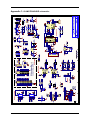
Appendix 1: IO-iMOTIONCUBE schematics ....................................................... 24
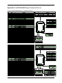
Appendix 2: iMOTIONCUBE Plug-in Connector Pin-out ..................................... 25

Technosoft 2020 6 IO-iMOTIONCUBE Technical Reference
1 Safety information
Read carefully the information presented in this chapter before carrying out the drive
installation and setup! It is imperative to implement the safety instructions listed hereunder.
This information is intended to protect you, the drive and the accompanying equipment during the
product operation. Incorrect handling of the drive can lead to personal injury or material damage.
Only qualified personnel may install, setup, operate and maintain the drive. A “qualified person” has
the knowledge and authorization to perform tasks such as transporting, assembling, installing,
commissioning and operating drives.
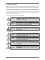
The following safety symbols are used in this manual:
WARNING!
SIGNALS A DANGER TO THE
OPERATOR WHICH MIGHT
CAUSE BODILY INJURY. MAY INCLUDE INSTRUCTIONS TO
PREVENT THIS SITUATION
CAUTION!
SIGNALS A DANGER FOR THE DRIVE WHICH MIGHT DAMAGE
THE PRODUCT OR OTHER EQUIPMENT. MAY INCLUDE
INSTRUCTIONS TO AVOID THIS SITUATION
CAUTION!
Indicates areas SENSITIVE TO electrostatic discharges (ESD)
WHICH REQUIRE HANDLING IN AN ESD PROTECTED
ENVIRONMENT
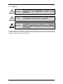
1.1 Warnings
WARNING!
THE VOLTAGE USED IN THE DRIVE MIGHT CAUSE
ELECTRICAL SHOCKS. DO NOT TOUCH LIVE PARTS WHILE
THE POWER SUPPLIES ARE ON
WARNING!
TO AVOID ELECTRIC ARCING AND HAZARDS, NEVER
CONNECT / DISCONNECT WIRES FROM THE DRIVE WHILE
THE POWER SUPPLIES ARE ON
WARNING!
THE DRIVE MAY HAVE HOT SURFACES DURING
OPERATION.
WARNING!
DURING DRIVE OPERATION, THE CONTROLLED MOTOR
WILL MOVE. KEEP AWAY FROM ALL MOVING PARTS TO
AVOID INJURY

Technosoft 2020 7 IO-iMOTIONCUBE Technical Reference
1.2 Cautions
CAUTION!
THE POWER SUPPLIES CONNECTED TO THE DRIVE MUST
COMPLY WITH THE PARAMETERS SPECIFIED IN THIS
DOCUMENT
CAUTION!
TROUBLESHOOTING AND SERVICING ARE PERMITTED ONLY
FOR PERSONNEL AUTHORISED BY TECHNOSOFT
CAUTION!
THE DRIVE CONTAINS ELECTROSTATICALLY SENSITIVE
COMPONENTS WHICH MAY BE DAMAGED BY INCORRECT
HANDLING. THEREFORE THE DRIVE SHALL BE REMOVED
FROM ITS ORIGINAL PACKAGE ONLY IN AN ESD PROTECTED
ENVIRONMENT
To prevent electrostatic damage, avoid contact with insulating materials, such as synthetic fabrics
or plastic surfaces. In order to discharge static electricity build-up, place the drive on a grounded
conductive surface and also ground yourself.

Technosoft 2020 8 IO-iMOTIONCUBE Technical Reference
2 Product Overview
2.1 Introduction
The IO-iMOTIONCUBE extension board is an auxiliary module allowing rapid evaluation of the
iMOTIONCUBE-CAN or iMOTIONCUBE-CAT, Intelligent Servo Drives.
2.2 Key Features
• Motor supply: +11…. +80 V
DC
• Logic supply: +9…. +36 V
DC
• STO supply: +18…. +40 V
DC
(if available on the drive)
• Direct access to the following iMOTIONCUBE I/O signals, via spring type terminals
connectors:
• 4 digital inputs, 12-36V (PNP or NPN):
o 2 general – purpose inputs: IN0, IN1
o 2 limit switch inputs: IN2/LSP (positive) and IN3/LSN (negative)
• 4 digital outputs, 5-36V, 0.5A (NPN open-collector/TTL pull-up):
o 2 general-purpose outputs: OUT0, OUT1
o One Error output: OUT2/Error
o One Ready output: OUT3/Ready
• 2 analog inputs, 0-5V,12-bit used to read:
o One analogue Reference: REF or general purpose
o One analogue Feedback sensor: FBDK or general purpose
• Micro USB connector for communication with the PC
• Two RJ 45 for EtherCAT communication
1
or CAN
2
communication
• Feedback #1 available connectors: 2x5 pin shrouded header, 2.54mm pitch
• Feedback #2 connector: 2x5 pin shrouded header, 2.54mm pitch
1
Usable only with the IO-CAT version (p.n. P025.326.E221)
2
Usable only with the IO-CAN version (p.n. P025.326.E201)

Technosoft 2020 9 IO-iMOTIONCUBE Technical Reference
2.3 IO-iMOTIONCUBE Board Dimensions
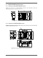
2.3.1 Dimensions without iMOTIONCUBE mounted
Figure 2.3.1 presents the IO-iMOTIONCUBE CAN/CAT board dimensions without the
iMOTIONCUBE mounted. All dimensions are in mm.
Figure 2.3.1. IO-iMOTIONCUBE board dimensions
2.3.2 Dimensions with iMOTIONCUBE mounted
Figure 2.3.1 presents the IO-iMOTIONCUBE CAN/CAT board dimensions with the iMOTIONCUBE
mounted. All dimensions are in mm.
Figure 2.3.2. IO-iMOTIONCUBE + iMOTIONCUBE dimensions

Technosoft 2020 10 IO-iMOTIONCUBE Technical Reference
3 Hardware Installation
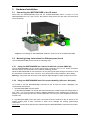
3.1 Connecting the iMOTIONCUBE to the IO board
Push down the iMOTIONCUBE drive into the IO-iMOTIONCUBE board. J1,2,4,5,6,7 of the
iMOTIONCUBE into J1,2,4,5,6,7 the IO. Be careful to align all the pins with their connectors and
not to bend them.
Figure 3.1.1 Installing an iMOTIONCUBE CAN/CAT-STO drive in the IO-iMOTIONCUBE
3.2 Mounting/using instructions for different power levels
The IO iMOTIONCUBE can be used in the following ways:
3.2.1 Using the iMOTIONCUBE as a starter kit with low currents (MAX 2A)
The IO iMOTIONCUBE has low current pass through connectors for J1 to J7. These connectors
allow the drive to be connected to the IO without soldering needed.
While the iMOTIONCUBE is connected to the IO only through the pass through connectors, it must
be used with a current limit of 2A, not more. This current limit is set by software in Drive Setup.
Warning: using more than 2A on the motor phases might damage the pass-through connectors.
3.2.2 Using the iMOTIONCUBE with full current capability (20A nom, 40A peak)
To be able to use the iMOTIONCUBE connected to the IO with full current capabilities, two
requirements must be met:
1. The iMOTIONCUBE must be cooled.
Fit the iMOTIONCUBE onto a heat sink that must keep the outside metal case temperature to
max. 70⁰C. It is up to the user to scale the radiator depending on the material type, conductivity,
passive or active cooling and motor current amplitudes. In the end, the case temperature must not
exceed 70⁰C.
2. The iMOTIONCUBE power and motor connectors must be soldered to the IO board on the
specific golden pads of each connector in order not to damage the existing pass-through
connectors.
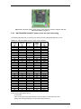
Figure 3.2.1
shows which pads must be soldered after the iMOTIONCUBE is mounted on the board.

Technosoft 2020 11 IO-iMOTIONCUBE Technical Reference
Figure 3.2.1 Specific golden power pads on the IO which must be soldered after the
iMOTIONCUBE is plugged in
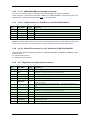
3.2.3 iMOTIONCUBE CAN/CAT power losses for heat sink scaling
The following table presents an estimation of power losses of the iMOTIONCUBE CAN or CAT.
Table 3.2.1 –iMOTIONCUBE CAN/CAT Power losses estimation
Vmot
Voltage
(V)
Phase
Current
(A)
Phases
PWM
(kHz)
Power
losses
(W)
48
10
3
20
5.69
48
10
3
40
6.33
48
10
3
60
6.96
48
10
3
80
7.59
48
10
4
20
6.67
48
10
4
40
7.53
48
10
4
60
8.40
48
10
4
80
9.20
80
10
3
20
6.15
80
10
3
40
7.19
80
10
3
60
8.28
80
10
3
80
9.32
80
10
4
20
7.25
80
10
4
40
8.63
80
10
4
60
10.06
80
10
4
80
11.50
48
20
3
20
12.77
48
20
3
40
13.57
48
20
3
60
14.38
48
20
3
80
15.24
48
20
4
20
16.10
48
20
4
40
17.19
48
20
4
60
18.29
48
20
4
80
19.38
80
20
3
20
13.28
80
20
3
40
14.66
80
20
3
60
16.10
80
20
3
80
17.42
80
20
4
20
16.79
80
20
4
40
18.63
80
20
4
60
20.47
80
20
4
80
22.31
Power losses might depend also on:
· 5V extra load
· Value of +Vlog (18V offers better efficiency than 24V which is much better than 36V)
· Steady state working temperature (cooler means better efficiency)

Technosoft 2020 12 IO-iMOTIONCUBE Technical Reference
3.3 Connectors
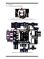
3.3.1 Connectors Layout and Description
Figure 3.3.1 IO Back side where J1 to J7 connectors are present.
The J1 to J7 connector pinouts are explained in the iMOTIONCUBE User Manual or Datasheet.
Figure 3.3.2. Top view of the IO-iMOTIONCUBE connectors

Technosoft 2020 13 IO-iMOTIONCUBE Technical Reference
3.3.2 J1..J7 – iMOTIONCUBE pass through connectors
The J1 to J7 connector pinouts are explained in the iMOTIONCUBE User Manual or Datasheet.
These connectors cannot hold the full current capability of the iMOTIONCUBE. The power pins have to be
soldered to their specific pads. Read Chapter 3.2.2 for more information.
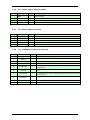
3.3.3 J8, J9 – CAN connector for -CAN drives and IO PN P025.326.E201
Pin Pin name Type Function
1 Can-Hi I/O CAN-Bus positive line (dominant high)
2 Can-Lo I/O CAN-Bus negative line (dominant low)
3 GND - Return ground for CAN-Bus
4, 5 - - Reserved. Do not use.
6..8 n.c. - Not connected
Remark: The CAN network must have at least one 120Ω terminal resistor connected between CAN-Hi and
CAN-Lo wires to function. JP11 can connect an on-board 120Ω resistor between CAN-Hi and CAN-Lo.
3.3.4 J8, J9 – EtherCAT connector for -CAT drives and IO PN P025.326.E221
J8 and J9 are standard RJ45 Ethernet connectors, compatible with IEEE802.3 100BASE-T (100Mbit/s). Accept
STP/UTP wiring.
J8 – EtherCAT IN connector
J9 – EtherCAT OUT connector
3.3.5 J10 – Digital I/O and analog inputs connector
Pin Pin name Type Function
1
+5V
OUT
O 5V output supply for I/O usage
2 REF I
Analogue input, 12-bit, 0-5V. Used to read an analog position, speed or torque
reference, or used as general purpose analogue input
3 IN0 I 5-36V general-purpose digital PNP/NPN input
4 GND - Return ground for I/O pins
5
IN3/LSN
I
5-36V digital PNP/NPN input. Negative limit switch input
6 OUT2/Error O
5-36V 0.5A, drive Error output, active low, NPN open-collector/TTL pull-up. Also
drives the red LED
7 +V
LOG
I
Positive terminal of the logic supply: 9 to 36V
DC
; Internally connected to all +V
LOG
pins
8 GND - Return ground for I/O pins
9 FDBK I
Analogue input, 12-bit, 0-5V. Used to read an analogue position or speed feedback
(as tacho), or used as general purpose analogue input
10 IN1 I 5-36V general-purpose digital PNP/NPN input
11 IN2/LSP I 5-36V digital PNP/NPN input. Positive limit switch input
12 OUT0 O 5-36V 0.5A, general-purpose digital output, NPN open-collector/TTL pull-up
13 OUT3/Ready O
5-36V 0.5A, drive Ready output, active low, NPN open-collector/TTL pull-up. Also
drives the green LED.
14 OUT1 O 5-36V 0.5A, general-purpose digital output, NPN open-collector/TTL pull-
up

Technosoft 2020 14 IO-iMOTIONCUBE Technical Reference
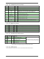
3.3.6 J11 – Power supply input connector
Pin Pin name Type Function
1 Earth -
Earth connection
2 +V
LOG
I/O Logic supply: +9 to +36V
DC;
Internally connected to all +V
LOG
pins
3
GND
- Negative return (ground) of the power supply
4 +V
MOT
I Positive terminal of the motor supply: 12 to 80V
DC
.
3.3.7 J12 – Motor output connector
Pin Pin name Type Function
1 A/A+ O Phase A for 3-ph motors, A+ for 2-ph steppers, Motor+ for DC brush motors
2
B/A-
O
Phase B
for 3-ph motors, A- for 2-ph steppers, Motor- for DC brush motors
3 C/B+ O Phase C for 3-ph motors, B+ for 2-ph steppers
4 CR/B- O Chopping resistor / Phase B- for step motors
5 Earth - Earth connection
3.3.8 J13 – Feedback #1 connector (2x5 pin)
Pin Pin name Type Function
1
GND
-
Return ground for sensors supply
2
+5V Out O
+5V
OUT
output supply (generated by iPOS drive)
3
GND
- Return ground for sensors supply
4 Temp Mot I NTC/PTC input. Used to read an analog temperature value
5
A1- /Sin-/ LH1
I
Incr. encoder1 A- diff. input, or analog encoder Sin- diff. input, or Linear Hall 1
analogue input
6 A1+/Sin+
I
Incr. encoder1 A single-ended, or A+ diff. input, or analogue encoder Sin+ diff.
input
7 B1-/Cos-/LH2
I
Incr. encoder1 B- diff. input, or analogue encoder Cos- diff. input, or Linear Hall
2 analogue input
8
B1+/Cos+
I
Incr. encoder1 B single-ended, or B+ diff. input, or analogue encoder Cos+ diff.
input
9 Z1-/ LH3 I Incr. encoder1 Z- diff. input, or Linear Hall 3 analogue input
10 Z1+ I Incr. encoder1 Z single-ended, or Z+ diff. input

Technosoft 2020 15 IO-iMOTIONCUBE Technical Reference
3.3.9 J14 – Feedback #2 connector (2x5 pin)
Pin Pin name Type Function
1
GND
-
Return ground for sensors supply
2
+5V Out O
+5V
OUT
output supply (generated by iPOS drive)
3
GND
- Return ground for sensors supply
4 FDBK I
Analogue input, 12-bit, 0-5V. Used to read an analogue position or speed
feedback (as tacho), or used as general purpose analogue input;
5
A2- /Pulse-/ Data-
/SL-
I
Incr. encoder2 A- diff. input, or Pulse-, or Data- for SSI, or Slave- for BiSS; has
120Ω resistor between pins 5 and 6
6
A2+/Pulse+/
Data+/SL+
I
Incr. encoder2 A+ diff. input, or Pulse+, or Data+ for SSI, or Slave+ for BiSS;
has 120Ω resistor between pins 5 and 6
7 B2-/Dir-/CLK-/MA-
I/O
Incr. encoder2 B- diff. input, or Dir-, or Clock- for SSI, or Master- for BiSS; has
120Ω resistor between pins 7 and 8
8
B2+/Dir+/CLK+/MA+
I/O
Incr. encoder2 B+ diff. input, or Dir+, or Clock+ for SSI, or Master+ for BiSS; has
120Ω resistor between pins 7 and 8
9 Z2- I Incr. encoder2 Z- diff. input; has 120Ω resistor between pins 9 and 10
10 Z2+ I Incr. encoder2 Z+ diff. input ; has 120Ω resistor between pins 9 and 10
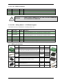
3.3.10 J15 –Digital hall connector
Pin Pin name Type Function
1 +5ViPOS O +5V
OUT
output supply (generated by iPOS drive)
2 GND - Ground
3 GND - Ground
4 HALL1 I Hall 1 digital sensor input
5 HALL2 I Hall 2 digital sensor input
6 HALL3 I Hall 3 digital sensor input
3.3.11 J17 – STO (Safe Torque Off) connector
Pin Pin name Type Function
1 STO2+ I
Safe Torque Off input 2, positive
input(opto-isolated, 18÷40V)
Apply between both STO1+, STO2+ and STO1-,
STO2- 24V DC for motor PWM output operation
2 STO1+ I
Safe Torque Off input 1, positive input
(opto-isolated, 18÷40V)
3 STO2- I
Safe Torque Off input 2, negative return
(opto-isolated, 0V)
4 STO1-
I
Safe Torque Off input 1, negative return
(opto-isolated, 0V)
Remarks: - This connector is valid only for drives with STO inputs.
- The STO inputs can be bypassed using the SS1 sliding switch functions.
3.3.12 J18 – USB connector
J18 is a standard micro USB connector, used for communication between the iPOS and PC.

Technosoft 2020 16 IO-iMOTIONCUBE Technical Reference
3.3.13 J19 – RS232 connector
Pin Pin name Type Function
1 TX232 O RS-232 Data Transmission
2 GND - Ground
3 RX232 I RS-232 Data Reception
CAUTION!
WHILE USING CONNECTOR J19, THE J18
USB CONNECTOR
MUST REMAIN UNCONNECTED.
3.3.14 SS1 – Sliding Switch 1 – STO/Enable bypass
This switch serves as an alternative to connecting wires to J17.
Pin Pin name Type Function
1 ENA1 bypass
-
Connects the ENA1 input to STO1+ pin; Remark - do not set this pin when working
with iMOTIONCUBE STO version; This setting is for PN P025.126.E101
2 ENA2 bypass
-
Connects the ENA2 input to STO2+ pin; Remark - do not set this pin when working
with iMOTIONCUBE STO version; This setting is for PN P025.126.E101
3
STO1- to GND
-
Connects the STO1- input to GND
4 STO2- to GND - Connects the STO2- input to GND
5 STO1+ to +Vlog - Connects the STO1+ input to +Vlog
6 STO2+ to +Vlog - Connects the STO2+ input to +Vlog
3.4 Mating connectors
Image Connector
Description
Manufacturer
Part Number Image
J12 Supply input, 4x5.08 female counter part for cable Camden
CTBA9208/4FL
J11 Motor power, 5x5.08 female counter part for cable Camden
CTBA9208/5FL
J3, J4
C-Grid III™ Crimp Terminal
MOLEX
90119-0109
J3, J4
C
-Grid III™ Crimp Housing Dual Row, 10 Circuits, with retention
MOLEX
90142-0010
C-Grid III™ Crimp Housing Dual Row, 10 Circuits, without
ention
90143-0010
J15
MICROFIT RECEPTACLE HOUSING, 2x3 WAY
MOLEX
43025-0600
J10
MICROFIT RECEPTACLE HOUSING, 2x
7 WAY MOLEX 43025-1400
J17
MICROFIT RECEPTACLE HOUSING, 2x2 WAY
MOLEX
43025-0400
J10, J15,
J17
CRIMP
PIN, MICROFIT, 5A MOLEX 43030-0007
J8, J9
Standard 8P8C modular jack (RJ
-45) male - -

Technosoft 2020 17 IO-iMOTIONCUBE Technical Reference
3.5 Jumper settings
0 = Jumper OFF; 1 = Jumper ON; 1-2 – pin 1 and 2 connected; 2-3 – pin 2 and 3 connected
Jumper
Name
Jumper Function Option Result
JP1 Enc A1/Sin termination
1-2
Do not connect a 120Ω resistor between A1+/Sin+ and A1-/Sin-
2-3
Connect a 120Ω resistor between A1+/Sin+ and A1-/Sin-
OFF
Use J13 pin 5 as Linear Hall 1 input
JP2 Enc B1/Cos termination
1-2
Do not connect a 120Ω resistor between B1+/Cos+ and B1-/Cos-
2-3
Connect a 120Ω resistor between B1+/Cos+ and B1-/Cos-
OFF
Use J13 pin 3 as Linear Hall 2 input
JP3 Enc Z1 termination
1-2
Do not connect a 120Ω resistor between Z1+ and Z1-
2-3
Connect a 120Ω resistor between Z1+ and Z1-
OFF
Use J13 pin 1 as Linear Hall 3 input
JP5 AxisID0_MSB
1-2
Connect AxisID0 input to +5V
DC
2-3
Connect AxisID0 input to GND
OFF
Leave input unconnected
JP6 AxisID0_LSB
1-2
Don’t connect a pull-up/pull-down resistor to AxisID0
2-3
Connect a pull-up/pull-down 4.7K Ω resistor to AxisID0
OFF
Connect a pull-up/pull-down 22K Ω resistor to AxisID0
JP7 AxisID1_MSB
1-2
Connect AxisID1 input to +5V
DC
2-3
Connect AxisID1 to GND
OFF
Leave input unconnected
JP8 AxisID1_LSB
1-2
Don’t connect a pull-up/pull-down resistor to AxisID1
2-3
Connect a pull-up/pull-down 4.7K Ω resistor to AxisID1
OFF
Connect a pull-up/pull-down 22K Ω resistor to AxisID1
JP9 AxisID2_MSB
1-2
Connect AxisID2 to +5V
DC
2-3
Connect AxisID2 to GND
OFF
Leave input unconnected
JP10 AxisID2_LSB
1-2
Don’t connect a pull-up/pull-down resistor to AxisID2
2-3
Connect a pull-up/pull-down 4.7K Ω resistor AxisID2
OFF
Connect a pull-up/pull-down 22K Ω resistor to AxisID2
JP11 CAN termination
0
Do not connect an 120Ω termination resistor between CAN Hi and
CAN Lo
1
Connect an 120Ω termination resistor between CAN Hi and CAN Lo
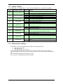
3.6 Default jumper settings
By default the I/O board is delivered with the jumpers in the following positions:
a. JP9, JP10, JP11 = OFF
b. JP6, JP8 = pos 1-2
c. JP1, JP2, JP3, JP5, JP7 = pos 2-3
The default axisID settings select the TMLCAN protocol with the axisID is 255. In order to quickly
change to CANopen protocol, set JP9 to pos 2-3 and JP10 to pos 1-2. The CANopen axisID set will be
127.
SS1 (STO bypass settings) has all switches set to OFF.
JP11 is OFF so no CAN termination resistor is present.

Technosoft 2020 18 IO-iMOTIONCUBE Technical Reference
3.7 Axis ID and CAN Protocol selection for CAN drives
The iMOTIONCUBE drive has 3 analogue inputs named AxisID0, AxisID1 and AxisID2 used to select the CAN
protocol: CANopen or Technosoft TMLCAN and the drive address or axis ID. The iMOTIONCUBE drive can
detect up to 7 different voltage levels on these 3 inputs. On the IO iMOTIONCUBE module the 7 voltage levels
can be selected via the jumpers: JP5, JP6, JP7, JP8, JP9 and JP10. Each AxisID input has 2 jumpers
associated. A 3-pin jumper is used to connect an Axis ID input to GND (position 2-3), +5V
DC
(position 1-2) or
leave it unconnected (OFF). Another 3-pin jumper is used to select how to do the connection: directly (position
1-2), via a pull-up / pull-down resistor of 4.7K Ω (position 2-3) or via a 22K resistor when left unconnected
(OFF). The 7 levels can be obtained using the following jumper positions:
Table 3.7.1 –Jumper setting for the seven voltage levels of AxisID0
Level
Connection needed
JP6
JP5
L0
Connect input directly to ground
1-2
2-3
L1
Connect input through a 4.7KΩ resistor to ground
2-3
2-3
L2
Connected input through a 22KΩ resistor to ground
OFF
2-3
L3
Nothing connected – leave input open
-
OFF
L4
Connect input through a 22KΩ resistor to +5V
DC
OFF
1-2
L5
Connect input through a 4.7Kohm resistor to +5V
DC
2-3
1-2
L6
Connect input directly to +5V
1-2
1-2
Table 3.7.2 –Jumper setting for the seven voltage levels of AxisID1
Level
Connection needed
JP8
JP7
L0
Connect input directly to ground
1-2 2-3
L1
Connect input through a 4.7KΩ resistor to ground
2-3
2-3
L2
Connected input through a 22KΩ resistor to ground
OFF
2-3
L3
Nothing connected – leave input open
-
OFF
L4
Connect input through a 22KΩ resistor to +5V
DC
OFF
1-2
L5
Connect input through a 4.7Kohm resistor to +5V
DC
2-3
1-2
L6
Connect input directly to +5V
1-2
1-2
Table 3.7.3 –Jumper setting for the seven voltage levels of AxisID2
Level
Connection needed
JP10
JP9
L0
Connect input directly to ground
1-2 2-3
L1
Connect input through a 4.7KΩ resistor to ground
2-3
2-3
L2
Connected input through a 22KΩ resistor to ground
OFF
2-3
L3
Nothing connected – leave input open
-
OFF
L4
Connect input through a 22KΩ resistor to +5V
DC
OFF
1-2
L5
Connect input through a 4.7Kohm resistor to +5V
DC
2-3
1-2
L6
Connect input directly to +5V
1-2
1-2
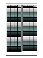
The CAN protocol selection is done via AxisID2:
• CANopen mode, if the input levels are: L0, L1 or L2
• TMLCAN mode, if the input levels are L3, L4, L5, L6
Remark: In CANopen mode, if the AxisID is set to 255, the drive remains “non-configured” waiting for a
CANopen master to configure it using CiA-305 protocol. A “non-configured” drive answers only to CiA-305
commands. All other CANopen commands are ignored and transmission of all other messages (including
boot-up) is disabled.

Technosoft 2020 19 IO-iMOTIONCUBE Technical Reference
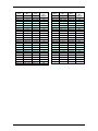
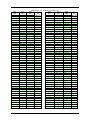
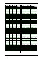
Table 3.7.4 – Axis ID setting in CANopen mode or EtherCAT drives
Axis
ID 2
Axis
ID 1
Axis
ID 0
ID
CANopen
JP10 | JP9
JP8 | JP7
JP6 | JP5
1-2 | 2-3 1-2 | 2-3 1-2 | 2-3 127
1-2 | 2-3
1-2 | 2-3
2-3 | 2-3
1
1-2 | 2-3
1-2 | 2-3
OFF | 2-3
2
1-2 | 2-3
1-2 | 2-3
OFF | OFF
3
1-2 | 2-3 1-2 | 2-3 OFF | 1-2 4
1-2 | 2-3
1-2 | 2-3
2-3 | 1-2
5
1-2 | 2-3
1-2 | 2-3
1-2 | 1-2
6
1-2 | 2-3
2-3 | 2-3
1-2 | 2-3
7
1-2 | 2-3 2-3 | 2-3 2-3 | 2-3 8
1-2 | 2-3
2-3 | 2-3
OFF | 2-3
9
1-2 | 2-3
2-3 | 2-3
OFF | OFF
10
1-2 | 2-3
2-3 | 2-3
OFF | 1-2
11
1-2 | 2-3 2-3 | 2-3 2-3 | 1-2 12
1-2 | 2-3
2-3 | 2-3
1-2 | 1-2
13
1-2 | 2-3
OFF | 2-3
1-2 | 2-3
14
1-2 | 2-3
OFF | 2-3
2-3 | 2-3
15
1-2 | 2-3 OFF | 2-3 OFF | 2-3 16
1-2 | 2-3
OFF | 2-3
OFF | OFF
17
1-2 | 2-3
OFF | 2-3
OFF | 1-2
18
1-2 | 2-3
OFF | 2-3
2-3 | 1-2
19
1-2 | 2-3 OFF | 2-3 1-2 | 1-2 20
1-2 | 2-3
OFF | OFF
1-2 | 2-3
21
1-2 | 2-3
OFF | OFF
2-3 | 2-3
22
1-2 | 2-3
OFF | OFF
OFF | 2-3
23
1-2 | 2-3 OFF | OFF OFF | OFF 24
1-2 | 2-3
OFF | OFF
OFF | 1-2
25
1-2 | 2-3
OFF | OFF
2-3 | 1-2
26
1-2 | 2-3
OFF | OFF
1-2 | 1-2
27
1-2 | 2-3 OFF | 1-2 1-2 | 2-3 28
1-2 | 2-3
OFF | 1-2
2-3 | 2-3
29
1-2 | 2-3
OFF | 1-2
OFF | 2-3
30
1-2 | 2-3
OFF | 1-2
OFF | OFF
31
1-2 | 2-3 OFF | 1-2 OFF | 1-2 32
1-2 | 2-3
OFF | 1-2
2-3 | 1-2
33
1-2 | 2-3
OFF | 1-2
1-2 | 1-2
34
1-2 | 2-3 2-3 | 1-2 1-2 | 2-3 35
1-2 | 2-3
2-3 | 1-2
2-3 | 2-3
36
1-2 | 2-3
2-3 | 1-2
OFF | 2-3
37
1-2 | 2-3
2-3 | 1-2
OFF | OFF
38
1-2 | 2-3 2-3 | 1-2 OFF | 1-2 39
1-2 | 2-3
2-3 | 1-2
2-3 | 1-2
40
1-2 | 2-3
2-3 | 1-2
1-2 | 1-2
41
1-2 | 2-3
1-2 | 1-2
1-2 | 2-3
42
1-2 | 2-3 1-2 | 1-2 2-3 | 2-3 43
1-2 | 2-3
1-2 | 1-2
OFF | 2-3
44
1-2 | 2-3
1-2 | 1-2
OFF | OFF
45
1-2 | 2-3
1-2 | 1-2
OFF | 1-2
46
1-2 | 2-3 1-2 | 1-2 2-3 | 1-2 47
1-2 | 2-3
1-2 | 1-2
1-2 | 1-2
48
2-3 | 2-3
1-2 | 2-3
1-2 | 2-3
49
Axis
ID 2
Axis
ID 1
Axis
ID 0
ID
CANopen
JP10 | JP9
JP8 | JP7
JP6 | JP5
2-3 | 2-3 1-2 | 2-3 2-3 | 2-3 50
2-3 | 2-3
1-2 | 2-3
OFF | 2-3
51
2-3 | 2-3
1-2 | 2-3
OFF | OFF
52
2-3 | 2-3
1-2 | 2-3
OFF | 1-2
53
2-3 | 2-3 1-2 | 2-3 2-3 | 1-2 54
2-3 | 2-3
1-2 | 2-3
1-2 | 1-2
55
2-3 | 2-3
2-3 | 2-3
1-2 | 2-3
56
2-3 | 2-3
2-3 | 2-3
2-3 | 2-3
57
2-3 | 2-3 2-3 | 2-3 OFF | 2-3 58
2-3 | 2-3
2-3 | 2-3
OFF | OFF
59
2-3 | 2-3
2-3 | 2-3
OFF | 1-2
60
2-3 | 2-3
2-3 | 2-3
2-3 | 1-2
61
2-3 | 2-3 2-3 | 2-3 1-2 | 1-2 62
2-3 | 2-3
OFF | 2-3
1-2 | 2-3
63
2-3 | 2-3
OFF | 2-3
2-3 | 2-3
64
2-3 | 2-3
OFF | 2-3
OFF | 2-3
65
2-3 | 2-3 OFF | 2-3 OFF | OFF 66
2-3 | 2-3
OFF | 2-3
OFF | 1-2
67
2-3 | 2-3
OFF | 2-3
2-3 | 1-2
68
2-3 | 2-3
OFF | 2-3
1-2 | 1-2
69
2-3 | 2-3 OFF | OFF 1-2 | 2-3 70
2-3 | 2-3
OFF | OFF
2-3 | 2-3
71
2-3 | 2-3
OFF | OFF
OFF | 2-3
72
2-3 | 2-3
OFF | OFF
OFF | OFF
73
2-3 | 2-3
OFF | OFF
OFF | 1-2
74
2-3 | 2-3 OFF | OFF 2-3 | 1-2 75
2-3 | 2-3
OFF | OFF
1-2 | 1-2
76
2-3 | 2-3
OFF | 1-2
1-2 | 2-3
77
2-3 | 2-3
OFF | 1-2
2-3 | 2-3
78
2-3 | 2-3 OFF | 1-2 OFF | 2-3 79
2-3 | 2-3
OFF | 1-2
OFF | OFF
80
2-3 | 2-3
OFF | 1-2
OFF | 1-2
81
2-3 | 2-3
OFF | 1-2
2-3 | 1-2
82
2-3 | 2-3 OFF | 1-2 1-2 | 1-2 83
2-3 | 2-3
2-3 | 1-2
1-2 | 2-3
84
2-3 | 2-3
2-3 | 1-2
2-3 | 2-3
85
2-3 | 2-3
2-3 | 1-2
OFF | 2-3
86
2-3 | 2-3 2-3 | 1-2 OFF | OFF 87
2-3 | 2-3
2-3 | 1-2
OFF | 1-2
88
2-3 | 2-3
2-3 | 1-2
2-3 | 1-2
89
2-3 | 2-3
2-3 | 1-2
1-2 | 1-2
90
2-3 | 2-3 1-2 | 1-2 1-2 | 2-3 91
2-3 | 2-3
1-2 | 1-2
2-3 | 2-3
92
2-3 | 2-3
1-2 | 1-2
OFF | 2-3
93
2-3 | 2-3
1-2 | 1-2
OFF | OFF
94
2-3 | 2-3 1-2 | 1-2 OFF | 1-2 95
2-3 | 2-3
1-2 | 1-2
2-3 | 1-2
96
2-3 | 2-3
1-2 | 1-2
1-2 | 1-2
97
OFF | 2-3
1-2 | 2-3
1-2 | 2-3
98
OFF | 2-3 1-2 | 2-3 2-3 | 2-3 99

Technosoft 2020 20 IO-iMOTIONCUBE Technical Reference
Axis
ID 2
Axis
ID 1
Axis
ID 0
ID
CANopen
JP10 | JP9
JP8 | JP7
JP6 | JP5
OFF | 2-3 1-2 | 2-3 OFF | 2-3 100
OFF | 2-3
1-2 | 2-3
OFF | OFF
101
OFF | 2-3
1-2 | 2-3
OFF | 1-2
102
OFF | 2-3
1-2 | 2-3
2-3 | 1-2
103
OFF | 2-3 1-2 | 2-3 1-2 | 1-2 104
OFF | 2-3
2-3 | 2-3
1-2 | 2-3
105
OFF | 2-3
2-3 | 2-3
2-3 | 2-3
106
OFF | 2-3
2-3 | 2-3
OFF | 2-3
107
OFF | 2-3 2-3 | 2-3 OFF | OFF 108
OFF | 2-3
2-3 | 2-3
OFF | 1-2
109
OFF | 2-3
2-3 | 2-3
2-3 | 1-2
110
OFF | 2-3
2-3 | 2-3
1-2 | 1-2
111
OFF | 2-3 OFF | 2-3 1-2 | 2-3 112
OFF | 2-3
OFF | 2-3
2-3 | 2-3
113
OFF | 2-3
OFF | 2-3
OFF | 2-3
114
OFF | 2-3
OFF | 2-3
OFF | OFF
115
OFF | 2-3 OFF | 2-3 OFF | 1-2 116
OFF | 2-3
OFF | 2-3
2-3 | 1-2
117
OFF | 2-3
OFF | 2-3
1-2 | 1-2
118
OFF | 2-3
OFF | OFF
1-2 | 2-3
119
OFF | 2-3 OFF | OFF 2-3 | 2-3 120
OFF | 2-3
OFF | OFF
OFF | 2-3
121
OFF | 2-3
OFF | OFF
OFF | OFF
122
OFF | 2-3
OFF | OFF
OFF | 1-2
123
Axis
ID 2
Axis
ID 1
Axis
ID 0
ID
CANopen
JP10 | JP9
JP8 | JP7
JP6 | JP5
OFF | 2-3 OFF | OFF 2-3 | 1-2 124
OFF | 2-3
OFF | OFF
1-2 | 1-2
125
OFF | 2-3
OFF | 1-2
1-2 | 2-3
126
OFF | 2-3
OFF | 1-2
2-3 | 2-3
255
OFF | 2-3 OFF | 1-2 OFF | 2-3 255
OFF | 2-3
OFF | 1-2
OFF | OFF
255
OFF | 2-3
OFF | 1-2
OFF | 1-2
255
OFF | 2-3
OFF | 1-2
2-3 | 1-2
255
OFF | 2-3 OFF | 1-2 1-2 | 1-2 255
OFF | 2-3
2-3 | 1-2
1-2 | 2-3
255
OFF | 2-3
2-3 | 1-2
2-3 | 2-3
255
OFF | 2-3
2-3 | 1-2
OFF | 2-3
255
OFF | 2-3 2-3 | 1-2 OFF | OFF 255
OFF | 2-3
2-3 | 1-2
OFF | 1-2
255
OFF | 2-3
2-3 | 1-2
2-3 | 1-2
255
OFF | 2-3
2-3 | 1-2
1-2 | 1-2
255
OFF | 2-3 1-2 | 1-2 1-2 | 2-3 255
OFF | 2-3
1-2 | 1-2
2-3 | 2-3
255
OFF | 2-3
1-2 | 1-2
OFF | 2-3
255
OFF | 2-3
1-2 | 1-2
OFF | OFF
255
OFF | 2-3 1-2 | 1-2 OFF | 1-2 255
OFF | 2-3
1-2 | 1-2
2-3 | 1-2
255
OFF | 2-3
1-2 | 1-2
1-2 | 1-2
255
Page is loading ...
Page is loading ...
Page is loading ...
Page is loading ...
Page is loading ...
Page is loading ...
-
 1
1
-
 2
2
-
 3
3
-
 4
4
-
 5
5
-
 6
6
-
 7
7
-
 8
8
-
 9
9
-
 10
10
-
 11
11
-
 12
12
-
 13
13
-
 14
14
-
 15
15
-
 16
16
-
 17
17
-
 18
18
-
 19
19
-
 20
20
-
 21
21
-
 22
22
-
 23
23
-
 24
24
-
 25
25
-
 26
26


Technosoft IO iMOTIONCUBE CAT Technical Reference
- Type
- Technical Reference
- This manual is also suitable for
Ask a question and I''ll find the answer in the document
Finding information in a document is now easier with AI
Related papers
Other documents
-
Zebra POS TC Product Reference Guide
-
 RoboteQ Advanced User manual
-
Delta Tau ACC-24M2A User manual
-
Arctic SOUND E 221 W Datasheet
-
Vaisala vLog 4.5 User manual
-
Elmo Duo Series User manual
-
Lika AMM80 User manual
-
-
 SYNAPTICON SOMANET Node 400 User manual
-
Sega THUNDER FORCE III User manual

