Page is loading ...

-1- -3- -4- -5--2-
-6- -8- -9- -10--7-
Red and black
connecting
wires:
These are the
power con-
nections of the
camera.
Connect the red wire with the DC12V+ of the power adaptor
and connect the black wire with the DC12V- of the power
adaptor.
Do NOT insert the adaptor into a wall socket yet.
Yellow and purple connecting wires:
Connect these wires
with an electric door
opener according to
the gure below, which
allows you to remotely
open the door via your
smartphone or tablet.
The operating instructions for the electric door opening can
be found in ‘IDC-25 Setup & Operation’.
*: An electric door opener with power source is NOT included.
Grey and white connecting wires:
Connect these wires
with the original door-
bell according to the
gure below, to ensure
the bell keeps function-
ing as before when
somebody rings it.
**: original doorbell
and bell transformer
of the residence or
building.
4. APP download.
download and install the APP
“SafeSmart” via the ‘App Store’
(see 1)
Attention: If you’re asked
for permission to accept
notications (messaging) during the
installation of the app, please also
accept that.
5. To create an account.
open the app and click ‘regis-
ter’ (see 2)
select ‘By email’ (see 3)
(registration via mobile
number is not supported)
click ‘Next’ (see 4)
Now insert one of the LAN cable plugs into the 8-pin
contra plug and the other plug of the LAN cable into a
free connection on the router.
Now please continue at chapter 7.
Wi-Fi antenna
Screw the supplied antenna onto the antenna wire of the
camera.
insert the power adaptor of the camera into
a wall socket and wait for approx. 25 sec-
onds until beep tones are emitted (see 8)
Attention: When removing the camera from the
metal holder, please keep the little black anti-
tampering button at the rear depressed, otherwise the
siren will sound to indicate a tampering attempt.
Please refer to chapter 9 if no beep tones are
emitted after 25 seconds.
make sure that the smartphone
or tablet is connected to the Wi-Fi
network
press the button (see 9)
in the APP, click the option
‘Set Wi by QR code’
(see 10)
click ‘network’ and enter
the network name (see 11)
enter the password of the
network (see 12)
click ‘Next’ (see 13)
the smartphone or tablet
will now show a QR code
which contains the ac-
cess code of the network
(see 14)
now move the
smartphone or
tablet with the QR
code at a distance
of approx. 15 to
20 cm in front of
the camera until
after several sec-
onds a “CHING”
tone is emitted; the
camera has now read the code (see 15)
you may have to increase the brightness of the
smartphone or tablet for a better scan result
click the ‘Heard’ button after
the “Ching” has sounded
(see 16)
the camera will now register itself on the network which
may take several seconds
“Setup successfully” will be briey shown in the display
after a successful registration.
7. To pair the camera to a smartphone or tablet.
(only for LAN users: insert the power adaptor of the
camera into a 230V wall socket)
click ‘ ’ (see 17), swipe
down (see 18) and wait until
the camera is displayed in
the ‘device list’
at the top of the list (see 19)
the device number of the
camera is shown (in this
example it’s 446589)
press the white part at the
left of the + (see 20)
assign a personal name to
the camera and repeat this
(see 21)
press ‘Save’ to save this
camera (see 22)
*** THE CAMERA IS NOW READY FOR USE ***
If ‘Connection failed’ appears in the display,
please rst perform the reset procedure (see
chapter 9) and start again at chapter 6.
See “DCI-25 SETUP” for registering this camera to a
second smartphone or tablet
8. Use the space below to write down the various pass-
words and save this manual in the packaging of this
door camera to keep everything together for future
reference.
create account / log-in:
email address:
(account) password:
account number:
(see instruction 1
in ‘DCI-25 SETUP)
log into the network:
name of the network:
(Wi-Fi) password:
Camera:
device number:
camera name:
camera password:
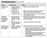
9. Possible problems when registering the camera on
the network.
As is described at gure 15, the camera obtains the
log-in information via a QR code from the smartphone or
tablet. If for any reason this code must be read again, the
camera must rst be reset. Also when no beep tones are
emitted (see gure 8) or when you suspect any fault, the
camera must rst be reset.
The reset is performed as follows:
1. Remove the adaptor from the wall socket.
2. Remove the Allen screw at the bottom of the camera
and take the camera out of the holder.
3. Press and hold the anti-
tampering button at the rear
of the camera.
4. Insert the adaptor into a wall
socket and wait for 20 sec-
onds (keep pressing the
anti-tampering button).
5. Use a paperclip to press
and hold the reset button
at the rear of the camera
for approx. 5 seconds until
you here a DING tone; the
camera is now reset.
6. You can now remove the adaptor from
the wall socket and also release the
anti-tampering button.
7. Replace the camera into the holder and fasten the
Allen screw.
8. Now continue at chapter 6.
IDC-25 INSTALLATION
iOS
1. Introduction.
This installation guide describes how the IDC-25 IP door
camera must be installed on the smartphone to see
who’s ringing the doorbell. Please refer to ‘IDC-25 Setup
& Operation’ manual printed on the other side of this user
manual for setup and user instructions.
2. Anti-tampering push-button.
At the rear of the camera you’ll nd a small
push-button. As soon as this little push-button
gets released, e.g. because the camera is being removed
from the holder, the camera will emit an alarm tone. So
please remove the adaptor from the wall socket when the
camera is removed from the holder.
3. Electric camera connection.
Push-connectors:
Attention: the supplied push-connectors are one-time
use only. When rst registering and setting up and then
later performing the permanent installation, it’s recom-
mended to rst connect the wires only temporarily (e.g.
using a lustre terminal). Only use the push-connectors for
permanent placement.
Using the push-connectors:
push the stripped wires
as far as possible into the
connector
now squeeze it tight using
a pair of pincers
the number on the orange cover
has no user function.
enter the email address for
sending the password to in
case it ever gets lost (see 5)
enter your own personal pass-
word twice (see 6)
(max. 27 characters, keep
in mind that upper-case and
lower-case letters and special
symbols are allowed)
click ‘Next’ (see 7) If the text ‘email
has been registered’ appears at this
point, it means that an account has
already been created for this email address; please enter a
different email address.
6. To register the camera on the network.
You can choose to connect the camera wirelessly, via the
supplied WiFi antenna, with a 2.4GHz router (network) or
through a LAN cable.
LAN cable:
Arrange the 4 wires in the supplied 8-pin contra plug ac-
cording to the gure below and clamp them down by clos-
ing the cover and pushing it tight.
(tip: this can be performed for each wire separately, a
clamped down wire will not be released anymore when
opening the cover)
*** LAN cable is not included.
DC12V+
DC12V-
Red
Black
Yellow
Purple
*
White
Grey
**
1
*
**
Tip: here the original bell
pusher was connected
2
3
4
5
6
7
1
2
3
4
5
6
7
8
***
the wires must be stripped
after 25 sec.:
‘bi...bi’
8
9
10
netwerk
13
11
12
14
“CHING”
smartphone:10-15cm
tablet: 20cm
15
16
CAM446589
18
20
17
19
CAM446589
21
22
5 sec.
1
Service
Help
Service Help
WWW.HESDO.NL
NL 073 6411 355
(Lokaal tarief)
BE 03 238 5666
(Lokaal tarief)
(Tarif local)
DE 0180 503 0085
Lokale Festnetzkosten
Hesdo, Australiëlaan 1
5232 BB, ‘s-Hertogenbosch
The Netherlands
WWW.HESDO.NL
NL 073 6411 355
BE 03 238 5666
DE 0180 503 0085
Hesdo, Australiëlaan 1, 5232 BB,
‘s-Hertogenbosch,
The Netherlands
(Lokaal tarief)
(Tarif local)
(Lokaal tarief)
(Lokale Festnetzkosten)
orange/white
orange
green/white
green

-1- -3- -4- -5--2-
-6- -8- -9- -10--7-
2. Camera settings.
open the App
press (2)
select
when using multiple came-
ras, click here the desired
camera and make sure the
camera is ‘online’
click ‘Settings’
• Date and Time: to set the time
and date, in UTC enter the devi-
ation in relation to the “Coordi-
nated Universal Time”
during standard time: UTC+1
during daylight saving time:
UTC+2
• Media Settings: when a play-
back device is connected to the
smartphone or tablet, here you
can set whether this is a PAL or
NTSC based device.
• Security Settings: to change the camera password or to
add one guest user by entering a personal code and pres-
sing ‘Save’ in the top right corner. Attention: when entering
another new guest user, the old user will be overwritten.
• Network Settings: this shows whether the connection is
established via a LAN cable (ethernet) or wirelessly
(Wi-Fi); this option also shows the available networks.
• Alarm Settings:
- “Receive alarm message”: when set the 0, doorbell
calls will not be registered on the phone; please set this
to I for normal use.
- “Alarm push ID”: Overview of the accounts that receive
notications from this camera (max. 5 accounts per
camera)
- “Alarm email”: the email address you enter here recei-
ves a photo of the person ringing the doorbell or of the
motion detected by the camera (see ‘Motion detection’
below). Keep in mind that the receipt of these emails
can be somewhat delayed in case of bad internet con-
nections or busy servers.
- “Motion detection”: to have the camera react ALSO to
motion in addition to the push-button. Keep in mind that
this makes the camera less suitable as a doorbell and
more as a motion alarm.
For reactions to motion, the lock
must be locked. When the lock
symbol is opened, the camera
will only react to the doorbell and
not to any motion.
Change this setting by pressing
the lock, the door camera will
emit a beep tone and the lock will
then either open of close.
- “Buzzer”: when set to I (on) and
the camera detects any motion
while the lock is closed, a siren
will sound from the camera which stops automatically
after 1, 2 or 3 minutes (adjustable after enabling this
function). This is why it’s recommended to set this
function to 0 (off).
- “PIR detection”: unavailable
• Record Settings:
- “Manual Recording”: use the ‘Record Switch’ switch to
instantly start or stop recording.
- “Alarm Recording”: the recording starts automatically
as soon as somebody presses the doorbell (or in case
of motion); here you can also adjust the recording
duration.
- Scheduled Recording”: to start camera recordings at a
preset time.
4. To add a new camera or to register it to another
smartphone.
open the App
press (4)
press ‘+’
select ‘Manual’ and enter
the camera ID and then
the camera password (this
is the device code, see
also ‘IDC-25 Installation’,
item 4.3)
click ‘Save’
IDC-25 OPERATION
iOS
1. Viewing camera image.
open the App
press (1)
click
the smartphone or tablet starts
searching for the camera
the camera image will then appear on the smartphone
see the next page for an explanation of the buttons
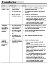
2. Somebody rings the bell.
the smartphone is activated and the image like the gure
below will appear on the phone while the set ringtone will
sound.
Press
‘View’ to
answer
the call
the following functions are now available:
2.1: actual date and time (see ‘IDC-25 Setup’)
2.2: no function
2.3: indication that the microphone of the smartphone
or tablet is enabled
2.4: press and hold this button for at least 1 second
to activate the electric door opener (the opener
remains powered for 5 seconds, after opening wait
at least 10 seconds before the door can be opened
again)
2.5: indication that the speaker of the smartphone is
enabled; press this button to change to ‘ ’, the
speaker is now turned off, press again to turn the
speaker back on; by default the speaker is swit-
ched on each time, it’s not possible to change this
standard setting
2.6: press to make a photo of your visitor, see also the
next chapter
2.7: to disconnect the camera
2.8: to enable or disable the microphone (when the
microphone is disabled, the microphone icon (2.3)
will not be displayed); by default the microphone is
switched on each time, it’s not possible to change
this standard setting
2.9: this shows the image resolution, you can choose
from:
HD: 1280*720 pixels
SD: 640*360 pixels (standard)
LD: 320*180 pixels
After start-up, ‘SD’ will be selected automatically
2.10: this shows the number of smartphones or tablets
currently watching this image
3. Making photos:
while wat-
ching, press
the
button to
make a
photo of
the current
image
Viewing photos:
Open the App
Press (3)
Click ‘Snapshot’
Press to delete photos
(all photos will be deleted)
4. Viewing videos:
See ‘Record Settings’ in
‘IDC-25 Setup’ for making
video recordings
Open the App
Press (4)
Press (5)
Click ‘Playback’ and click
the desired video
The le names of these videos
provide the following informa-
tion:
2015-07-14_08:23:59_A.av (180S)
date time A= Alarm recording length (*)
(doorbell pusher or motion)
M= Manual recording
S= Scheduled recording
- Above the list of recorded videos, you can set the day or
period to simplify searching for specic recordings.
- All recordings will be deleted when you format the
SD card (see IDC-25 Setup, chapter 2, item ‘Storage
Setting’).
- It’s not possible to copy or move recordings to external
devices.
- In ‘Alarm Recording’ and with the camera set to motion
detection, the recording will stop 1, 2 or 3 minutes after
the last movement. This means that the total length of
a video may be a lot longer than the 1, 2 or 3 minutes
you’ve set.
5. Shake.
Use the ‘Shake’ (5) option to
have to camera search for all
registered cameras on the
network.
6. Alarm Management.
In ‘Alarm logs’ (6), a list will
appear with the times and
dates when the doorbell was
pressed or when the doorbell
camera detected movement.
7. No function.
DISCARDING THE DEVICE (ENVIRONMENT)
At the end of its useful live, this product may not
be discarded as regular domestic waste; it must be
brought to a collection point for the recycling of electric and
electrical equipment.
V1.0
IDC-25 SETUP
iOS
1. System settings.
Open the App and press the (1) button to open the
‘System Settings’ menu
• at the top of the screen you’ll nd the account number
• Account: this option shows the account information and
allows you to make changes
• About: to check the rmware version
• Log out: allows you to log out
• Defence Area: unavailable
• Storage Info: the doorbell camera contains a built-in SD
card of 8GB. This menu shows the total and remaining
memory capacity. This menu also allows you to format
the SD card (keep in mind that formatting the card will
delete all recordings).
The card is not accessible from the outside and cannot
be replaced.
The built-in SD card has a capacity of 8GB which is
enough for approx. 100 hours of continuous recording
(approx. 80MB per hour). When the card is full, the
oldest recording will be overwritten.
• Device Update: here you can have the App search for
any available updates for the camera software.
3. Camera name and password.
open the App
press (3)
select
when using multiple came-
ras, click here the desired
camera and make sure the camera
is ‘online’
click ‘Edit’
• Device Name: to assign a per-
sonal name to the camera
• Device password: to assign
a personal password to the
camera
press ‘Cancel’
to ignore the
call, a notica-
tion will now
appear to in-
form you that
all new calls
for the coming
10 seconds
will not be
registered
2.10
2.9
2.72.6
2.2
2.1
2.52.4
2.3
2.8
1
4
3
2
1
5
4
+
3
5
6
3
2
7
/