Raypak 302C-902C User manual

Type
User manual
This manual should be maintained in legible condition and kept adjacent to the heater or in another safe place
for future reference.
Catalog No: 1000.57I Effective: 02-27-13 Replaces: 07-22-10 P/N 241275 Rev. 10
INSTALLATION & OPERATING
INSTRUCTIONS
Cold Water Start & Cold Water Run
For Hi Delta, MVB & Raytherm
Heaters & Boilers
2
Rev. 10 reflects the following:
Changes to:
Additions:
Deletions:
None
None
Illustrated Parts List (was on previous pages 34-39)
CONTENTS
WARNINGS 4
GENERAL SAFETY 5
Time/Temperature Relationships in
Scalds 5
COLD WATER START 6
Installation 6
Check Power Source 6
Mounting the Control Box 6
Installing the Temperature Sensor 7
Connecting the Valve Assembly 7
Connecting Power to the Controller 8
Connecting Boiler to Cold Water Start 8
Operation 8
Cold Start Sequence of Operation 9
Troubleshooting 10
Mounting the Actuator to the Valve 11
Mounting Brackets 11
Locating the Rotation Stop 11
Drive Linkage 12
Verifying B
all Position 12
Actuator to Valve Orientation 12
Installing the Three-Way Valve 13
High Pressure Tab 13
Actuator 13
Cold Water Start Troubleshooting
Guide 14
Typical Cold Water Start Piping 15
Wiring Diagram 16
Heater Interface Wiring 17
CWS—MULTIPLE BOILER 18
Materials Included 18
Installation 18
Mounting the Control Boxes 18
Installing the Temperature Sensor 18
Installing the Three-Way Valve 18
Connecting Power to the Controller 18
Connecting Cold Water Start to Multi-
Heater Interlock Box 18
Connecting Heater to Cold Water Start
Multi-Heater Interlock 18
Actuator to Valve Orientation 19
Three-Way Valve Ball Orientation 19
Valve Installation 19
4 Inch Valve Orientation 20
Connecting the Actuator 20
Typical Cold Water Start Multiple Boiler
Piping 21
Wiring Diagram 22
COLD WATER RUN 23
Purpose 23
Typical Cold Water Run Applications 23
CWR vs. CWS 23
Installation 23
Installation Codes 23
Mounting the
Control B
ox 23
Injector & Heater Pump Comparison 24
Check the Power Source 25
Injector Pump Wiring 25
Injection Pump Cover Installation 27
Typical Cold Water Run Piping -
Heating Applications 29
Typical Cold Water Run Piping -
Pool Applications 29
Operation 30
Cold Run Sequence of Operation 30
Cold Water Run Troubleshooting
Guide 31
Wiring Diagrams 32
REPLACEMENT PARTS 34
3
4
DANGER:
Indicates the presence of immediate hazards which will cause severe person-
al injury, death or substantial property damage if ignored.
WARNING:
Indicates the presence of hazards or unsafe practices which could cause
severe personal injury, death or substantial property damage if ignored.
CAUTION:
Indicates the presence of hazards or unsafe practices which could cause
minor personal injury or product or property damage if ignored.
NOTE:
Indicates special instructions on installation, operation, or maintenance which
are important but not related to personal injury hazards.
WARNINGS
Pay Attention to These Terms
NOTE: Piping diagrams in this manual are not
intended to replace an engineered piping system.
NOTE: Minimum 18 AWG, 105°C, stranded wire
must be used for all low voltage (less than 30 volts)
external connections to the unit. Solid conductors
should not be used because they can cause exces-
sive tension on contact points. Install conduit as
appropriate. All high voltage wires must be the same
size (105°C, stranded wire) as the ones on the unit
or larger.
NOTE: Consult the factory for units with a 30 pound
pressure relief valve (PRV).
GENERAL SAFETY
To meet commercial hot water use needs, the high
limit safety control on this water heater is adjustable up
to 210°F. However, water temperatures over 125°F
c
an cause instant severe burns or death from scalds.
When supplying general purpose hot water, the rec-
ommended initial setting for the temperature control is
125°F.
Safety and energy conservation are factors to be con-
sidered when setting the water temperature on the
thermostat. The most energy-efficient operation will
result when the temperature setting is the lowest that
satisfies the needs of the application.
Water temperature over 125°F can cause instant
severe burns or death from scalds. Children, disabled
and elderly are at highest risk of being scalded.
Feel water before bathing or showering.
Temperature limiting valves are available.
Maximum water temperatures occur just after the
heater’s burner(s) have shut off. To determine the
water temperature being delivered, turn on a hot water
faucet and place a thermometer in the hot water
stream and read the thermometer.
5
NOTE: When this water heater is supplying general
purpose hot water for use by individuals, a thermo-
statically controlled mixing valve for reducing point of
use water temperature is recommended to reduce
the risk of scald injury. Contact a licensed plumber or
the local plumbing authority for further information.
Water temperature over 125°F can
cause instant severe burns or death
from scalds.
Children, disabled, and elderly are
at highest risk of being scalded.
See instruction manual before set-
ting temperature at water heater.
Feel water before bathing or show-
ering.
Temperature limiting valves are
available, see manual.
Time/Temperature
Relationships in Scalds
The following chart details the relationship of water
temperature and time with regard to scald injury and
may be used as a guide in determining the safest
water temperature for your applications.
Water
Temp.
Time to Produce
Serious Burn
120°F More than 5 minutes
125°F 1-1/2 to 2 minutes
130°F About 30 seconds
135°F About 10 seconds
140°F Less than 5 seconds
145°F Less than 3 seconds
150°F About 1-1/2 seconds
155°F About 1 second
Table courtesy of The Shriners Burn Institute
Table A: Time to Produce Serious Burn
COLD WATER START
Before beginning the installation, it's important to first
i
nspect the system and determine what materials you
will need. Some parts are included with the controller
while others you will need to provide.
1 Control Box
1 Temperature Sensor
1 Valve assembly with actuator (Shipped separately)
Wiring and mounting hardware (Provided by installer)
Installation
Check the Power Source
Check the power source:
AC = 108 VAC Minimum, 132 VAC MAX
AB = 108 VAC Minimum, 132 VAC MAX
BC = <1 VAC Maximum
Mounting the Control Box
The control box should be mounted on the side of the
heater to which the system piping and valve assembly
are to be attached as shown in Figs. 4–8. The con-
troller should be mounted so as to provide maximum
support by using the mounting holes provided on the
base of the controller to the side center brace on the
heater. On MVB and Hi Delta models, locating dimples
are provided for ease of drilling the mounting holes.
You will need to drill mounting holes through the heater
side panel for the routing of wiring and the sensor.
CIRCUIT
B
REAKER
W
HITE
GROUND
B
LACK
GREEN
AB C
WARNING: Using a multi-meter, check the follow-
ing voltages at the breaker panel prior to connecting
any equipment. Make sure proper polarity is followed
and house ground is proven.
Fig. 2: Wiring Connections
Fig. 3: Multi-meter
CAUTION: Do not use for swimming pool applica-
tions
6
NOTE: After testing at the factory it may be prudent
to ship the piping assembly disassembled and
attached to the heater pallet. This is done to avoid
shipping damage and it must be reassembled on the
jobsite. Use Fig. 1 to assist in reassembling the pip-
ing.
Fig. 1: Cold Water Start Assembly
THREE-WAY VALV E
Fig. 4: Component Locations—Hi Delta
NOTE: Four knockouts are located on the bottom
o
f the control for ease of installation.
Models X Y Z
302B-902B
7 2 1-9/16
992B-2342B
13-1/4 1-5/16 6-5/8
LEFT SIDE
Fig. 5: Component Locations—Raytherm Models
514–824
11-1/8”
1”
10-5/16”
Fig. 6: Component Locations—Raytherm Models
926–1826
11-1/8”
11/16”
7-1/4”
7
Installing the Temperature
Sensor
A
void routing wiring on or near other electrical wires,
conduit, motors, spark igniters or other sources of high
i
ntermittent voltage or current. The sensor should be
placed in the dry well on the inlet header, or as indicat-
ed in the piping for multiple heaters, as shown on page
21. Ensure it is installed using thermal paste (field
supplied) and that it is held firmly at the bottom of the
well.
Connecting the Valve
Assembly
Connect the valve assembly into the bypass piping.
The branch (port B) is connected to the crossover pipe
(bypass between inlet and outlet). The actuator tail
stock should be oriented to point down. Refer to the
Actuator to Valve Orientation section.
Route wiring from the valve to the controller thru one
of the bottom panel conduit knockouts to TB2. Refer to
the wiring diagram provided on the inside of the con-
troller cover assembly.
CAUTION: Miswiring the actuator may cause
unwarrantable damage. Verify the wire colors
against the actuator make and model.
8
Connecting Power to the
Controller
Connect power from the 120 VAC power input of the
heater to the controller power inputs Terminal Block
(TB1). This is accomplished by connecting wiring from
the control box to the heater 120 VAC power input con-
nections. Refer to the heater wiring diagrams.
Fig. 9: Location of TB1 in Control Box
Operation
Verify the following upon a CALL FOR HEAT signal
from the heater:
1. CALL FOR HEAT: LED on PCB illuminates
GREEN.
2. START UP MODE: LED on PCB illuminates YEL-
LOW. It should go out in less than 7 minutes, as the
boiler inlet temperature approaches the setpoint
temperature.
3. The “ACTUATOR” should be in the fully open posi-
tion or move to the fully open position if not already
there. (Actuator and ball rotated to the at-rest CCW
position).
Reset Switch*
Connecting Boiler to Cold Water
Start
The installer must provide five 18AWG stranded wires
between the heater and the controller terminal block.
Wiring is to be run in separate conduit from line volt-
age to ensure proper operation. Refer to the diagrams
on page 17 for connection points depending on the
Raypak product being used.
Fig. 8: Component Locations—MVB
9-9/16”
5/16”
1-3/4”
INSTALL
INSULATION ON
INSIDE OF REAR
PANEL
CAUTION: Install the foil-faced insulation on the
inside of the rear panel of MVB heaters as indicated
in Fig. 8. Use spray adhesive or high temp foil tape
to attach the insulation. Ensure that the foil faces the
heat exchanger assembly. Failure to install this insu-
lation as directed can cause overheating of the com-
ponents and may void the warranty on the control.
*The reset switch may be located on the front control panel on some
MVB models.
22”
7
-5/8”
1-1/2”
Fig. 7: Component Locations—Raytherm Models
2100–4001
9
Cold Start Sequence of
Operation
1. 120VAC to heater sends 120VAC to Cold Start
control on terminal block 1.
2. 120/24VAC transformer and 120VAC-12VDC con-
verter are powered.
3. 120/24VAC transformer outputs 24VAC to pin 2 of
terminal block 2
4. 24VAC leaves pin 2 of terminal block 2 and goes
to the modulating three-way valve on the 20-
30VAC lead, and to the NO contacts of the SPST
relay located in the cold start control panel.
5
. 120VAC-12VDC converter outputs 12VDC to the
common terminal of the reset switch, located on
the bottom of the cold start control panel.
6. The 12VDC signal crosses over the reset switch
a
nd goes to Terminal FS on the cold start circuit
board.
7. Cold start control is now in standby until a Call for
Heat occurs at heater.
8. The heater outputs 24VAC to terminal 4 of termi-
nal block 3 located in Cold Start controller to
indicate a CFH from the heater.
9. Terminal 4 of TB 3 sends 24VAC to the coil of the
SPST relay located in the cold start control panel.
10. The SPST relay coil is energized and closes the
contacts allowing 24VAC to energize the CFH ter-
minal on the cold start circuit board.
a) A two second delay occurs from the CFH sig-
nal to the output of power from terminal MC of
the cold start circuit board.
11. 24 VAC is sent from terminal 2 of terminal block 3
to the NO contacts of the DPST relay located in
the cold start control panel.
12. After the two second delay on the cold start circuit
board, pin MC outputs a 24 VAC signal to the coil
of the DPST relay located in the cold start control
panel.
13. The DPST relay coil energizes and closes the NO
contacts.
14. Once the NO contacts of the DPST close, the
heater 24 VAC is sent back to the heater to com-
plete the circuit (pin 3 of terminal block 3) and the
interlock circuit (pin 1 & 2 of terminal block 3)
allowing the heater to fire.
15. Pin FR on the TVC board outputs 10VDC to the
modulating three-way valve actuator to drive it
fully open for two minutes waiting for the heater to
reach full fire.
16. After the two-minute delay the 10VDC output sig-
nal from pin FR reduces to approximately 8VDC.
17. The output signal continues to vary depending on
the heater inlet temperature.
NOTE: The minimum inlet water temperature to the
heater to prevent condensate is 105°F on heaters
with an efficiency of 85% or less, and 120°F on 87%
efficiency heaters. Ensure that during operation the
Setpoint Pot is adjusted properly.
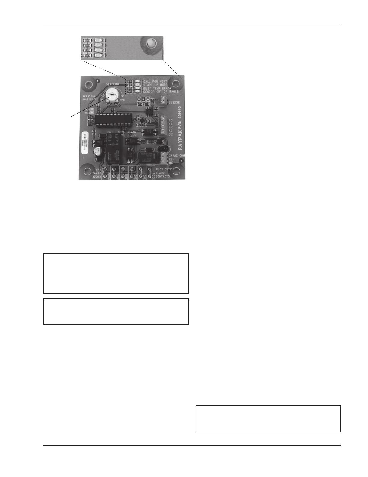
Setpoint
Pot
CALL FOR HEAT
START UP MODE
I
NLET TEMP ERROR
SENSOR OUT OF RANGE
Fig. 10: Control PCB
NOTE: If a “DIP” switch is provided on the control
PCB, verify that the switch settings are: 1 = OFF, 2 =
ON, 3 = OFF.
NOTE: The heater will lockout and shut down if the
setpoint on the inlet temperature is not achieved
within seven minutes from a call for heat.
4. If the control is operating properly, the “START UP
MODE” LED should go out in less than 7 minutes.
At this point, the inlet water temperature should be
stable at a temperature between 105°F and 120°F
corresponding to the Setpoint Pot setting on the
PCB. The actuator should have stopped moving.
D
IP SWITCH SETTINGS
F
OR 3-WAY ACTUATOR
VDC
0-10
DA
FIXED
~
mA
2-10
RA
AUTO
6-9
S
WITCH MUST BE IN THIS POSITION
TURN CLOCKWISE TO FURTHEST STOP
M
ODE SELECTION SWITCH
DIRECT ACTING, ON INCREASING SIGNAL
Fig. 11: Set Dip Switch Settings Delta Actuator
NOTE: The Elodrive actuator is NEMA 4 rated. No
outdoor cover is required.
Troubleshooting
Check your power source using a Volt-Ohm meter;
check the following voltages at TB1 terminal block:
TB1-1 to TB1-2 = 108 VAC Minimum, 132 VAC
Maximum
TB1-1 to TB1-3 = 108 VAC Minimum, 132 VAC
Maximum
TB1-2 to TB1-3 = Must be less than .6 VAC
IF CALL FOR HEAT LED does not illuminate when the
heater has a CFH signal, check for 24VAC between
pins 4 and 5 of TB3 on the cold start control. If voltage
is present, check wiring using the wiring diagram. If
voltage is not present, the problem exists in the heater.
IF VALVE DOES NOT MOVE: Check for voltage out at
TB2-1: Should be a 1VDC to 10VDC output to the
actuator valve. If no voltage is present, check for volt-
age at pin FS on the control board, there should be a
12VDC signal. If the 12VDC signal is not present, ver-
ify that the converter is wired correctly using the wiring
diagram.
IF INLET TEMP ERROR is illuminated: The setpoint
temperature has not been reached within the 7 minute
time period.
Push the Reset Switch (see Fig. 9) or remove
power and watch for proper operation.
Fig. 12: Delta Actuator Actuator Shown in Full
System Flow Position
DETENT MUST BE
SET TO POSITION 4
Fig. 13: Elodrive Actuator Rotation Knob Setting
Set adjustment knob to Position 4
S
IDE
“B”
NOTE:
SIDE “B” MUST
FACE AWAY
F
ROM VALVE
Fig. 14: Elodrive Actuator Actuator Shown in Full
System Flow Position
CAUTION: Delta actuator requires the use of the
factory-supplied weatherproof cover for outdoor
installations.
10
T
he DIP switches on the three-way valve actuator
must be set as indicated in the Fig. 11 below:
Mounting the Actuator to the
Valve
When mounting the actuator to the valve, ensure that
the valve stem is oriented with the machined flat notch
positioned parallel to the “A” and “AB” ports as shown
in Fig. 15.
All actuators used by Raypak include the “spring
return” safety feature. This means that upon loss of
power during operation the valve automatically rotates
back to the full system flow position avoiding high limit
lockouts or other issues.
Flat Notch
Fig. 15: Orient Notch Parallel with “A” and “AB” Ports
Check pump sizing and valve/piping sizing and cor-
rect as necessary.
IF SENSOR OUT OF RANGE LED is illuminated: The
sensor may have a short or open circuit.
Press and release the Reset Switch (see Fig. 9)
and watch for proper operation.
Replace sensor.
Check wiring using wiring diagram.
Flow
A
B
AB
11
Fig. 16: Elodrive Mounting Bracket
Mounting Brackets (Elodrive)
There are different actuator mounting brackets on the
three-way valves. When ordering a replacement
bracket you will receive the newest design available
f
rom the manufacturer. If it appears to be different than
the damaged bracket, the new and old are inter-
changeable and will fit all valve bodies. See Fig. 16.
Locating the Rotation Stop
(Elodrive)
An internal rotation stop device is built into the actua-
tor mounting bracket and this can be installed only two
ways for proper operation of the valve. The stop is
labeled on each side with either “D” or “P”. This indi-
cates that the valve is set up for either a diverting
application or proportional (mixing) application.
Raypak uses the three-way valve in a mixing applica-
tion therefore the “P” designator must be facing away
from the bracket.
The valve rotates in a clockwise direction when it is
operating. The rotational stop must be positioned so
that the drive linkage can rotate. The drive linkage is
keyed to allow only 90 degrees of rotation. Ensure that
the key is positioned so the linkage may rotate clock-
wise as shown in Fig. 17.
12
If you do not see two openings at this point, con-
tinue rotating the stem and ball until you do.
Once you can see two openings, STOP, as shown
i
n Fig. 18. Then rotate the stem counterclockwise
until only one opening remains e.g. you can see
c
ompletely through the valve (through ports A and
AB).
Now the ball is correctly oriented inside of the valve
body. Reassemble the valve, base and actuator, and
then install the assembly into your piping system as
indicated in this manual.
PORT AB
Fig. 18: Verifying Ball Position
POSITION ROTATIONAL
STOP SO THAT DRIVE
LINKAGE CAN ROTATE
Fig. 17: Elodrive Rotational Stop Positioning
Fig. 19: Recommended Orientation of Actuator
Actuator to Valve Orientation
Install the actuator so that the tail is pointing downward
as shown in Fig. 19. You may also install it horizontal-
ly, however, DO NOT mount it so that the tail is
pointing up as shown in Fig. 20. Doing so will allow
water and debris to collect in the cup where the wiring
exits the actuator, potentially causing damage.
Drive Linkage (Elodrive)
The drive linkage for the 2” NPT and 2-1/2” NPT three-
way valves originally were supplied with an orientation
groove in the end of the stem. This groove has now
been removed by the vendor. All new linkage stems
will have a smooth end. Using the groove to determine
ball position inside of the valve is not reliable and
should be avoided.
Verifying Ball Position
All field-installed valves must have the ball properly
positioned. Occasionally differences occur from the
manufacturer of the valve body. The square stem that
the drive linkage attaches to should have a machined
notch to verify ball position, however on occasion it is
not there. To properly orient the ball follow these
instructions PRIOR to installation into your plumbing
system.
Remove the actuator and base from the valve
body.
With port “AB” facing you, rotate the valve stem
approximately 45 degrees clockwise. You must
see two port openings if the ball is correctly orient-
ed.
13
Fig. 20: Incorrect Orientation of Actuator
Actuator
The ELODRIVE actuator has a manual override for the
valve. The label located over the silver colored primary
label states, “Please read manual before using manu-
al override”. Using the Allen wrench supplied with the
loose valve, place it in the hexagonal opening under
the label. See Fig. 22.
By pressing the red release button on the tail of the
actuator and simultaneously rotating the Allen wrench
you can rotate the ball clockwise. Once you release or
remove the Allen wrench the ball will return to its orig-
inal position by way of the “spring return”. This is an
easy way to determine if the ball is oriented properly
inside of the valve.
HIGH
PRESSURE
TAB
Fig. 21: High Pressure Tab
Installing the Three-Way Valve
When threading any pipe into the ports of the three-
way valve, a backing wrench MUST be employed. You
must capture the valve body with a secondary wrench
to avoid damaging the internal seals. Valve bodies
leaking from improper installation are non-war-
rantable.
High Pressure Tab
Located between the valve body and the actuator
mounting bracket, is a yellow tab labeled High
Pressure” see Fig. 21. This is for maintenance of the
valve only.
If the valve stem begins leaking beneath the yellow tab
the internal packing material must be replaced. The
“High Pressure” tab is held on with two screws located
under the mounting bracket.
To replace the packing material, all water pressure
must be removed from the valve assembly and the
assembly must be isolated from the system water.
Then remove the actuator and bracket, then remove
the two screws holding the “High Pressure” tab in
place.
At this point the packing material can be removed and
replaced just like any other valve assembly. The pack-
ing material is not available from Raypak.
INSERT ALLEN
WRENCH UNDER
THIS LABEL
Fig. 22: Actuator
Cold Water Start Troubleshooting Guide
Ste
p
9
Ste
p
8
Ste
p
10
Step 1
Step 2
Step 3
Step 4
Step 5
Step 6
Step 7
Is there a Call For
H
eat at the heate
r
?
Are the 120/24VAC
transformer and 120VAC-
12VDC inverter in the cold
start controller powered?
Replace 120VAC-12VDC
inverter or correct wiring.
D
oes the cold start 12VDC inverter
output 12VDC to the reset switch
and to common pin FS of the cold
start circuit board?
Does the cold start 120/24VAC
transformer output 24VAC to pin
2
of TB2 and the valve actuator?
Replace transformer or
correct the wiring
Replace circuit board
Are the terminals 1-4 of TB3
connected to N.O. contacts of
DPDT relay?
Does cold start DPDT
relay coil receive 24VAC
from MC on circuit board?
Are terminals 1-4 of TB3
correctly connected back
to the heater?
Call our Technical Service Department
1-805-278-5300
NO
Verify 120VAC at separate
c
ircuit breaker and correct.
YES
D
oes TB1 of cold start
controller have 120
V
AC?
Heater is in standby mode
Correct wiring to
match wiring diagram
YES
N
O
N
O
YES
Y
ES
N
O
N
O
NO
YES
YES
NO
The unit is okay
YES
NO
YES
Correct wiring
Is the actuator modulating after
2-1/2 minutes?
NO
Correct wiring
YES
Is the heater tripping the high
limit?
YES
NO
Verify actuator is set to reverse acting
and three-way valve is not installed
backwards.
2” & 2-1/2” valve must
rotate CW on decreasing 0-
10VDC signal. 4” valve will
rotate CCW.
YES
Correct settings or valve
orientation
NO
Is 24VAC present at CFH
terminal on cold start circuit
board?
Check and verify 24VAC between pin 4 and 5
of TB3 in cold start controller and correct.
Is 0-10VDC present at
connection FR of cold start
circuit board?
NO
Replace cold start circuit board
YES
NO
YES
Does cold start circuit board lock-out on
“Sensor out of Range”?
NO
YES
Is sensor resistance correct?
YES
NO
Replace sensor
Is system water
temperature
below 32ºF?
NO
YES
Does the reset switch send
12VDC to terminal FS on the
cold start circuit board?
NO
YES
14
NOTES:
1.LOCATE UNIONS TO FACILITATE SERVICING OF PLUMBING SIDE.
2.PLUMB SWING CHECK VALVE IN GRAVITY-CLOSED POSITION.
3.PIPE ALL RELIEF VALVES TO DRAIN, OR AS LOCAL CODES REQUIRE.
4.BUFFER TANK REQUIRED WHEN WATER VOLUME IN BOILER LOOP
ISNOT ADEQUATE TO PROVIDE STABLE TEMPERATURE CONTROL.
CONSULT FACTORY FOR TANK SIZING.
5.SYSTEM FLOW MUST EXCEED HEATER FLOW AT ALL TIMES.
Typical Cold Water Start Piping
15
BRACKET RESTS AGAINST
VALVE MOUNTING CHASIS
* VALVE NOT DEPICTED
Panel Control and Wrapper Control Cover Assembly
with Support Valve Cover; Full Assembly
Wiring Diagrams—Cold Water Start
16
HEATER INTERFACE WIRING FOR CWS OR CWR
CWS/CWR
C
ONTROL OR
MULTIPLE BOILER
INTERFACE
C
WS/CWR
C
ONTROL OR
M
ULTIPLE BOILER
INTERFACE
CWS/CWR
CONTROL OR
MULTIPLE BOILER
INTERFACE
17
Installing the Three-way Valve
Install three-way diverting valve into common boiler
piping manifold as shown in the diagram on page 18.
B
oiler common outlets to be connected at port AB.
Discharge to system from port A with bypass port
being port B. Common pipe sizing may be larger than
three-way valve port connections requiring the use of
increasers for installation (see Table B for valve siz-
ing). It is recommended that three-way valve be
installed as near the main system piping as is feasible.
Route control wiring in separate conduit to the Cold
Water Start control box and wire as shown in the dia-
gram on page 19.
Connecting Power to the Controller
Installer to provide a dedicated 120V circuit with local
disconnect to the Cold Water Start Control. Refer to
wiring Fig. 9 on page 8 for detailed instruction.
Connecting Cold Water Start to
Multi-Heater Interlock Box
Installer to provide four 18AWG stranded wires
between pins 7-10 on the Cold Start Control and 7-10
on the Multi-Boiler Interlock as shown in the diagram
on page 22. Do not use solid core wire when wiring
any portion of the Cold Start Multi-Boiler system.
Connecting Heater to Cold Water
Start Multi-Heater Interlock
Installer to provide five 18AWG stranded wires
between each boiler and Multi-Boiler Interlock box.
Wiring to be run in separate conduit from line voltage
to ensure proper operation. Refer to the diagram on
page 22 for connection points depending on Raypak
product being used.
COLD WATER START—
MULTIPLE HEATER
(Maximum 4 heaters)
Materials Included
1 Cold Start Control Box
1 Multi-Boiler Interlock Box
1 Water Sensor & Well
1 Three-way Diverting Valve assembly with Actuator
Installation
Mounting the Control Boxes
Cold Start Control and Multi-Boiler Interlock should be
mounted in such a manner as to allow for easy access
for wiring of the boiler interlock connections.
Installing the Temperature Sensor
Temperature sensor to be installed in a drywell with
thermal paste at the location indicated in the diagram
on page 21 to ensure proper operation of the control
system. Installer must ensure the drywell extends at
least 2 inches into the water flow path. Sensor wiring
must be run in separate conduit from line voltage and
should be a minimum of 18 AWG shielded cable. Refer
to diagram on page 22 for wiring information.
Total Load
(MBTU)
Valve
Size
Minimum
Pipe Size
Cv
Flow
Rate
(gpm)
Valve
Pressure
Drop
∆T @
Max Size
∆T @
Min. Size
Order
No.
600-1000 2” NPT 2 57 70 3.5 ft 22 14.4 012228
1001-1800 2.5” NPT 2.5 74 100 4.2 ft 30.2 16.8 012229
1801-2600 2.5” NPT 3 100 150 5.2 ft 29.1 20.1 012230
2601-4000 4” FLG* 4 152 220 4.8 ft 30.5 22.9 012231
4001-6000 4” FLG* 4 254 330 3.9 ft 30.5 20.3 012232
6001-8000 4” FLG* 6 327 440 4.2 ft 30.5 22.5 012233
Standard boiler pump options offered by Raypak may NOT be appropriate for these applications.
*CAUTION: Approved for closed loop systems only.
Table B: Valve Sizing Chart
NOTE: Flanges, bolts and gaskets for flanged
valves supplied by others.
18
Actuator to Valve Orientation
Install the actuator so that the tail is pointing horizon-
tally as shown in Fig. 26 or is pointing down. DO NOT
m
ount it so that the tail is pointing up as shown in Fig.
20. Doing so will allow water and debris to collect in
the cup where the wiring exits the actuator, potentially
causing damage.
Three-Way Valve Ball Orientation
The ball orientation must be verified prior to mounting
the flanged valve into the piping system. With the
flanged four-inch valve it is a fairly simple procedure.
Do not use the groove on the end of the drive linkage
to verify.
First, remove the actuator by removing the wing-nut
underneath the mount bracket near the tail. Second,
loosen the locking bolt on top of the actuator that
clamps to the drive linkage. See Fig. 23.
Once this has been done, remove the actuator by lift-
ing straight off the drive linkage shaft.
Now the ball position must be verified. Using pliers,
grasp the base of the drive linkage. While looking into
port AB, rotate the drive linkage counterclockwise
about 45 degrees. See Fig. 24. You should see two
partial openings similar to Fig. 18.
If you do not see the two partial openings after 45
degrees of rotation, continue rotating until you do.
Once you see the two partial openings, STOP. Now
rotate the shaft in the reverse direction (clockwise)
until you can see straight through to valve from port AB
to port A.
19
LOCKING BOLT
WING NUT
Fig. 23: Removing the Actuator (Elodrive)
Reinstall the actuator and bracket assembly in reverse
order, and ensure that the ball assembly is properly
oriented. Mount the flanged valve into your piping sys-
t
em in accordance with this manual.
Valve Installation
To properly install this valve port “AB” must be con-
nected to the combined outlet of the heater(s); and
port “B” must be attached to the bypass between the
combined inlet and the combined outlet, as shown on
page 21. The valve body has the port designators cast
into the drive linkage housing. See Fig. 25.
Fig. 24: Rotating the Drive Linkage
PORT AB
Fig. 25: Valve Orientation
20
NOTE: SIDE A MUST
FACE AWAY FROM
VALVE BODY
DETENT MUST BE
SET TO POSITION 2
NOTE: SIDE A
MUST FACE AWAY
FROM 4” VALVE BODY
Fig. 26: Valve Orientation (Elodrive Actuator)
4-Inch Valve Orientation
The valve must be installed so that the combined boil-
er outlets enter through Port "AB" (See Fig. 26). Port
"
B" is the bypass port and port "A" is the return to the
system (port designations are cast into the stem of the
v
alve body). The valve body should be installed so that
the actuator input shaft is in the vertical or horizontal
position. The Actuator stem should never be hanging
downward.
The actuator, as shipped from the factory, is in the hor-
izontal position when the valve is installed as shown in
Fig. 26. The actuator position can be changed to suit
job site conditions.
Under no circumstances should the actuator be posi-
tioned such that the electrical connection is pointing
upwards (see Fig. 20) as this can allow for moisture or
debris to enter the actuator assembly and potentially
damage the actuator.
Before installing into the piping system, verify the
valve is positioned properly by referring to Fig. 26 and
the diagram on page 21.
Connecting the Actuator
The 4-inch valve is shipped loose, and must be field
wired. Connect the actuator leads to the Cold Water
Start control panel, as indicated in the wiring diagram
on Page 16.
Fig. 27: Elodrive actuator used on 4” valves
(Actuator shown in full system flow position.)
The actuator for the 4” valves rotates opposite to the
direction of the smaller actuators. On an Elodrive
actuator, Side A must be facing away from the valve.
Fig. 28: Rotational Setting for Elodrive Actuator
Used on 4” Valves
  • Page 1 1
  • Page 2 2
  • Page 3 3
  • Page 4 4
  • Page 5 5
  • Page 6 6
  • Page 7 7
  • Page 8 8
  • Page 9 9
  • Page 10 10
  • Page 11 11
  • Page 12 12
  • Page 13 13
  • Page 14 14
  • Page 15 15
  • Page 16 16
  • Page 17 17
  • Page 18 18
  • Page 19 19
  • Page 20 20
  • Page 21 21
  • Page 22 22
  • Page 23 23
  • Page 24 24
  • Page 25 25
  • Page 26 26
  • Page 27 27
  • Page 28 28
  • Page 29 29
  • Page 30 30
  • Page 31 31
  • Page 32 32
  • Page 33 33
  • Page 34 34
  • Page 35 35
  • Page 36 36

Raypak 302C-902C User manual

Type
User manual

Ask a question and I''ll find the answer in the document

Finding information in a document is now easier with AI