ESAB Origo™Mig C250 3ph User manual
- Category
- Welding System
- Type
- User manual
This manual is also suitable for

Valid for serial no. 526, 527, 509, 5330349 301 102 060210
OrigoMig C170 3ph
OrigoMig C200 3ph
OrigoMig C250 3ph
Instruction manual

ENGLISH
− 2 −
TOCe
1 DIRECTIVE 3. . . . . . . . . . . . . . . . . . . . . . . . . . . . . . . . . . . . . . . . . . . . . . . . . . . . . . . .
2 SAFETY 3. . . . . . . . . . . . . . . . . . . . . . . . . . . . . . . . . . . . . . . . . . . . . . . . . . . . . . . . . . .
3 INTRODUCTION 5. . . . . . . . . . . . . . . . . . . . . . . . . . . . . . . . . . . . . . . . . . . . . . . . . . .
3.1 Equipment 5. . . . . . . . . . . . . . . . . . . . . . . . . . . . . . . . . . . . . . . . . . . . . . . . . . . . . . . . . . . . . . . .
4 TECHNICAL DATA 5. . . . . . . . . . . . . . . . . . . . . . . . . . . . . . . . . . . . . . . . . . . . . . . . .
5 INSTALLATION 6. . . . . . . . . . . . . . . . . . . . . . . . . . . . . . . . . . . . . . . . . . . . . . . . . . . .
5.1 Placing 6. . . . . . . . . . . . . . . . . . . . . . . . . . . . . . . . . . . . . . . . . . . . . . . . . . . . . . . . . . . . . . . . . . .
5.2 Assembly of components 6. . . . . . . . . . . . . . . . . . . . . . . . . . . . . . . . . . . . . . . . . . . . . . . . . . .
5.3 Electrical installation 7. . . . . . . . . . . . . . . . . . . . . . . . . . . . . . . . . . . . . . . . . . . . . . . . . . . . . . .
5.4 Mains power supply 7. . . . . . . . . . . . . . . . . . . . . . . . . . . . . . . . . . . . . . . . . . . . . . . . . . . . . . . .
6 OPERATION 8. . . . . . . . . . . . . . . . . . . . . . . . . . . . . . . . . . . . . . . . . . . . . . . . . . . . . . .
6.1 Connection and control devices 8. . . . . . . . . . . . . . . . . . . . . . . . . . . . . . . . . . . . . . . . . . . . .
6.2 Functions explanation 9. . . . . . . . . . . . . . . . . . . . . . . . . . . . . . . . . . . . . . . . . . . . . . . . . . . . . .
7 MAINTENANCE 9. . . . . . . . . . . . . . . . . . . . . . . . . . . . . . . . . . . . . . . . . . . . . . . . . . . .
7.1 Inspection and cleaning 9. . . . . . . . . . . . . . . . . . . . . . . . . . . . . . . . . . . . . . . . . . . . . . . . . . . .
8 FAULT TRACING 10. . . . . . . . . . . . . . . . . . . . . . . . . . . . . . . . . . . . . . . . . . . . . . . . . . .
9 ORDERING OF SPARE PARTS 10. . . . . . . . . . . . . . . . . . . . . . . . . . . . . . . . . . . . . .
DIAGRAM 11. . . . . . . . . . . . . . . . . . . . . . . . . . . . . . . . . . . . . . . . . . . . . . . . . . . . . . . . . . . .
WEAR COMPONENTS 16. . . . . . . . . . . . . . . . . . . . . . . . . . . . . . . . . . . . . . . . . . . . . . . . .
ACCESSORIES 17. . . . . . . . . . . . . . . . . . . . . . . . . . . . . . . . . . . . . . . . . . . . . . . . . . . . . . .

− 3 −
OC17253e
1 DIRECTIVE
DECLARATION OF CONFORMITY
ESAB Welding Equipment AB, S−695 81 Laxå, Sweden, gives its unreserved guarantee that welding
power source OrigoMig C170 3ph/OrigoMig C200 3ph/OrigoMig C250 3ph from serial number 526,
527, 509, 533 complies with standard IEC/EN 60974−1, in accordance with the requirements of direc-
tive (73/23/EEC) and addendum (93/68/EEC) and with standard EN 60974−10 in accordance with the
requirements of directive (89/336/EEC) and addendum (93/68/EEC).
−−−−−−−−−−−−−−−−−−−−−−−−−−−−−−−−−−−−−−−−−−−−−−−−−−−−−−−−−−−−−−−−−−−
Henry Selenius
Vice President
ESAB Welding Equipment AB
695 81 LAXÅ
SWEDEN Tel: + 46 584 81000 Fax: + 46 584 411924
Laxå 12−04−2005
2 SAFETY
Users of ESAB welding equipment have the ultimate responsibility for ensuring that anyone who
works on or near the equipment observes all the relevant safety precautions. Safety precautions
must meet the requirements that apply to this type of welding equipment. The following recommen-
dations should be observed in addition to the standard regulations that apply to the workplace.
All work must be carried out by trained personnel well−acquainted with the operation of the welding
equipment. Incorrect operation of the equipment may lead to hazardous situations which can result
in injury to the operator and damage to the equipment.
1. Anyone who uses the welding equipment must be familiar with:
S its operation
S location of emergency stops
S its function
S relevant safety precautions
S welding
2. The operator must ensure that:
S no unauthorised person is stationed within the working area of the equipment when it is
started up.
S no−one is unprotected when the arc is struck
3. The workplace must:
S be suitable for the purpose
S be free from draughts
4. Personal safety equipment
S Always wear recommended personal safety equipment, such as safety glasses, flame−proof
clothing, safety gloves.
S Do not wear loose−fitting items, such as scarves, bracelets, rings, etc., which could become
trapped or cause burns.
5. General precautions
S Make sure the return cable is connected securely.
S Work on high voltage equipment may only be carried out by a qualified electrician.
S Appropriate fire extinquishing equipment must be clearly marked and close at hand.
S Lubrication and maintenance must not be carried out on the equipment during operation.
GB

− 4 −
OC17253e
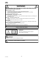
WARNING
READ AND UNDERSTAND THE INSTRUCTION MANUAL BEFORE INSTALLING OR OPERATING.
ARC WELDING AND CUTTING CAN BE INJURIOUS TO YOURSELF AND OTHERS. TAKE PRECAU-
TIONS WHEN WELDING. ASK FOR YOUR EMPLOYER’S SAFETY PRACTICES WHICH SHOULD BE
BASED ON MANUFACTURERS’ HAZARD DATA.
ELECTRIC SHOCK − Can kill
S Install and earth the welding unit in accordance with applicable standards.
S Do not touch live electrical parts or electrodes with bare skin, wet gloves or wet clothing.
S Insulate yourself from earth and the workpiece.
S Ensure your working stance is safe.
FUMES AND GASES − Can be dangerous to health
S Keep your head out of the fumes.
S Use ventilation, extraction at the arc, or both, to take fumes and gases away from your breathing zone
and the general area.
ARC RAYS − Can injure eyes and burn skin.
S Protect your eyes and body. Use the correct welding screen and filter lens and wear protective
clothing.
S Protect bystanders with suitable screens or curtains.
FIRE HAZARD
S Sparks (spatter) can cause fire. Make sure therefore that there are no inflammable materials nearby.
NOISE − Excessive noise can damage hearing
S Protect your ears. Use earmuffs or other hearing protection.
S Warn bystanders of the risk.
MALFUNCTION − Call for expert assistance in the event of malfunction.
PROTECT YOURSELF AND OTHERS!
WARNING!
Read and understand the instruction manual
before installing or operating.
Do not use the power source for thawing frozen pipes.
WARNING!
This product is solely intended for arc welding.
GB

− 5 −
OC17253e
3 INTRODUCTION
OrigoMig C170 3ph/C200 3ph/C250 3ph are step controlled power sources in a compact design,
intended for welding with solid steel, stainless steel or aluminium wire as well as tubular wire with or
without shielding gas.The possibility of welding with homogeneous wire/shielding gas and welding with
gasless tubular wire is obtained by switching the + and − connections on the switching terminal by the
wire feed unit.
ESAB’s accessories for the product can be found on page 17.
3.1 Equipment
The power source is supplied with:
S Welding gun
S Return cable with return clamp
S Shelf for gas cylinder
S Instruction manual
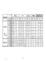
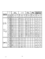
4 TECHNICAL DATA
OrigoMig C170 3ph OrigoMig C200 3ph OrigoMig C250 3ph
Voltage 400−415V
3∼ 50/60 Hz
400−415V
3∼ 50/60 Hz
230/400−415V
3∼ 50/60 Hz
Permissible load at
100% duty cycle 100A 120A 150A
60 % duty cycle 130A 150A 190A
35 % duty cycle 170A 200A 250A
Setting range (DC) 30−170A 30−200A 40−280A
Open circuit voltage 15,5−30,6V 16,0−31,8V 15,0−37,0V
Open circuit power 310W 210W 340W
Power factor at max load 0,97 0,97 0,97
Control voltage 42V, 50/60Hz 42V, 50/60Hz 42V, 50/60Hz
Wire feed speed 1,0−17m/min 1,0−17m/min 1,0−17m/min
Burnback time 0,02−0,25s 0,02−0,25s 0,02−0,25s
Spot welding 0,2−2,5s 0,2−2,5s 0,2−2,5s
Welding gun connection EURO EURO EURO
Wire dimension range 0,6−0,8(Fe, SS)
1,0(Al)
0,8(FCW)
0,8−1,0(CuSi)
0,6−1,0(Fe, SS)
1,0(Al)
0,8−1,0(FCW)
0,8−1,0(CuSi)
0,6−1,2(Fe, SS)
1,0−1,2(Al)
0,8−1,2(FCW)
0,8−1,0(CuSi)
Max diameter/weight
of wire bobin
300mm/15kg 300mm/15kg 300mm/15kg
Dimensions lxwxh 860x420x730 860x420x730 860x420x730
Weight 63,5kg 72,5kg 82kg
Operating temperature −10 ÷ +40
o
C −10 ÷ +40
o
C −10 ÷ +40
o
C
Enclosure class IP 23 IP 23 IP 23
Application classification
GB

− 6 −
OC17253e
Duty cycle
The duty cycle refers to the time as a percentage of a ten−minute period that you can weld at a cer-
tain load without overloading.
Enclosure class
The IP code indicates the enclosure class, i. e. the degree of protection against penetration by solid
objects or water. Equipment marked IP23 is designed for indoor and outdoor use.
Application class
The symbol indicates that the power source is designed for use in areas with increased
electrical hazard.
5 INSTALLATION
The installation must be executed by a professional.
WARNING!
This product is intended for industrial use. In a domestic environment this product may cause radio
interference. It is the user’s responsibility to take adequate precautions.
5.1 Placing
Position the welding power source such way that its cooling air inlets and outlets are
not obstructed.
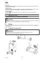
5.2 Assembly of components
For packing and shipment of the machine the wheels are detached from the unit.
Before use attach the wheels according to instruction.
WARNING!
1.
3.
2.
GB

− 7 −
OC17253e
5.3 Electrical installation
C200 3ph
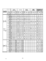
5.4 Mains power supply
Check that the unit is connected to the correct mains power supply voltage, and that it is protected by
the correct fuse size. A protective earth connection must be made, in accordance with regulations.
Rating plate with supply connection data
OrigoMig C170 3ph OrigoMig C200 3ph OrigoMig C250 3ph
Voltage V 400−415V, 3∼ 50/60 Hz 400−415V, 3∼ 50/60 Hz 230/400−415V, 3∼ 50/60 Hz
Current A
at 100% duty cycle
4,0 5,3 12,1/7,0
at 60% duty cycle 6,1 6,8 17,6/10,2
at 35% duty cycle 8,9 10,1 25,3/14,6
Cable area mm
2
4 x 1,5 4 x 1,5 4 x 2,5/4 x 1,5
Fuse slow A 10 10 25/16
NB: The mains cable areas and fuse sizes as shown above are in accordance with Swedish
regulations. They may not be applicable in other countries: make sure that the cable area and fuse
sizes comply with the relevant national regulations.
GB

− 8 −
OC17253e
6 OPERATION
General safety regulations for the handling of the equipment can be found on
page 3. Read through before you start using the equipment!
WARNING!
Rotating parts can cause injury, take great care.
WARNING − TIPPING RISK!
There is a risk of tipping while transportation and operation, if the welding machine leans
more than 10
o
. In that case appropriate securing has to be provided !
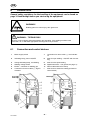
6.1 Connection and control devices
1 Mains supply switch 7 Connection for return cable (−), low inductan-
ce
2 Indicating lamp, power ON/OFF 8 Knob for spot welding − ON/OFF and time set-
ting
3 Orange indicating lamp, overheating 9 Knob for wire speed setting
4 Welding voltage switch 10 Digital instrument − V/A (option,see page 17)
5 EURO − connector for welding gun 11 Return cable with return clamp
6 Connection for return cable (−), high in-
ductance
* Knob for burn−back time setting (located on
control board)
C250 3phC170 3ph
C200 3ph
GB

− 9 −
OC17253e
6.2 Functions explanation
6.2.1 Overheating protection
When the machine is switched on with the mains switch [1], indicating lamp [2] is on and
lamp [3] off − the machine is ready to operate. If the internal temperature becomes too
high, the welding is interrupted and disabled. This state is indicated by lighting of the
orange indicating lamp [3] on the front of the machine. It resets automatically when the
temperature has fallen.
7 MAINTENANCE
Regular maintenance is important for safe, reliable operation.
Note!
All guarantee undertakings from the supplier cease to apply if the customer himself
attempts any work in the product during the guarantee period in order to rectify any
faults.
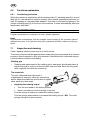
7.1 Inspection and cleaning
Check regularly that the power source is free from dirt.
The power source should be regularly blown clean using dry compressed air at reduced
pressure. More frequently in dirty environments. Otherwise the air inlet/outlet may be-
come blocked and cause overheating.
Welding gun
S Cleaning and replacement of the welding gun’s wear parts should take place at
regular intervals in order to achieve trouble−free wire feed. Blow the wire guide
clean regularly and clean the contact tip.
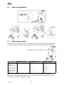
The brake hub
The hub is adjusted when delivered, if
readjustment is required, follow the instructions
below. Adjust the brake hub so that wire is slightly
slack when wire feed stops.
S Adjusting the braking torque:
S Turn the red handle to the locked position.
S Insert a screwdriver into the springs in the hub.
Turn the springs clockwise to reduce the braking torque
Turn the springs anticlockwise to increase the braking torque. NB: Turn both
springs through the same amount.
GB

− 10 −
OC17253e
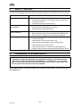
8 FAULT TRACING
Try these recommended checks and inspections before sending for an authorised service technican.
Type of fault
Actions
No arc S Check that the mains power supply switch is turned on.
S Check that the welding current supply and return cables are
correctly connected.
S Check that correct current value is set.
Welding current is interrupted
during welding
S Check whether the thermal overload trip has operated
(indicated by the orange lamp on the front).
S Check the main power supply fuses.
Thermal overload trips
operate frequently
S Check to see whether the air inlets/outlets are clogged.
S Make sure that you are not exceeding the rated data for the
power source (i.e. that the unit is not being overloaded).
Poor welding performance S Check that the welding current supply and return cables are
correctly connected.
S Check that the correct current value is set.
S Check that the correct welding wires are being used.
S Check the main power supply fuses.
S Check the wire feed unit − if proper rolls are applied and
properly set the pressure of the wire feeder’s pressure rollers
9 ORDERING OF SPARE PARTS
OrigoMig C170 3ph/C200 3ph/C250 3ph is designed and tested in accordance with the
international and European standards IEC/EN 60974−1 and EN 60974−10. It is the obli-
gation of the service unit which has carried out the service or repair work to make sure
that the product still conforms to the said standard.
Spare parts may be ordered through your nearest ESAB dealer, see the last page of
this publication.
GB

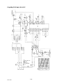
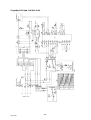
Diagram
− 11 −
dOC17253
OrigoMig C170 3ph, 400−415V

− 12 −
dOC17253
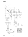
OrigoMig C200 3ph, 400−415V

− 13 −
dOC17253
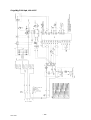
OrigoMig C250 3ph, 400−415V

− 14 −
dOC17253
OrigoMig C250 3ph, 230/400−415V

OrigoMig C170 3ph/C200 3ph/C250 3ph
Edition 060210
− 15 −
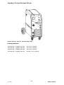
oOC17253
Valid for serial no. 526, 527, 509, 533−XXX−XXXX
Ordering numbers
0349 308 670 OrigoMig C170 3ph 400−415V 3~50/60Hz
0349 308 290 OrigoMig C200 3ph 400−415V 3~50/60Hz
0349 307 840 OrigoMig C250 3ph 400−415V 3~50/60Hz
0349 309 090 OrigoMig C250 3ph 230/400−415V 3~50/60Hz

OrigoMig C170 3ph/C200 3ph/C250 3ph
Edition060210
− 16 −
wOC17253
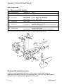
Wear components
(W. F. Mechanism 0455 890 890)
Item Denomination Ordering no. Notes
A Pressure roller 0455 907 001
B Feed roller
0367 556 001
0367 556 002
0367 556 003
0367 556 004
Ø 0.6−0.8mm Fe, Ss, cored wire.
Ø 0.8−1.0mm Fe, Ss, cored wire.
Ø 1.0−1.2mm Fe, Ss, cored wire.
Ø 1.0−1.2mm Al wire.
C Inlet nozzle 0466 074 001
D Insert tube
0455 894 001
0455 889 001
Plastic, must be used together with item 0455 885 001,
for welding with Al wire.
Steel, must be used together with item 0455 886 001.
E Outlet nozzle
0455 885 001
0455 886 001
Must be used together with item 0455 894 001,
for welding with Al wire.
Must be used together with item 0455 889 001.
The rollers are marked with wire dimension in mm, some are also marked with inch.
Welding with aluminium wires.
In order to weld with aluminium wires, proper rollers, nozzles and liners for
aluminium wires MUST be used. It is recommended to use 3m long welding gun for
aluminium wires, equipped with appropriate wear parts.

OrigoMig C170 3ph/C200 3ph/C250 3ph
Edition 060210
Accessories
− 17 −
aOC17253
Digital meter . . . . . . . . . . . . . . . . . . . . . . . . . . . . 0349 302 598
Transformer kit for CO
2
heater . . . . . . . . . . . 0349 302 250
Polarity change KIT . . . . . . . . . . . . . . . . . . . . . 0349 309 310

− 18 −
hints

− 19 −
hints

− 20 −
hints
Page is loading ...
-
 1
1
-
 2
2
-
 3
3
-
 4
4
-
 5
5
-
 6
6
-
 7
7
-
 8
8
-
 9
9
-
 10
10
-
 11
11
-
 12
12
-
 13
13
-
 14
14
-
 15
15
-
 16
16
-
 17
17
-
 18
18
-
 19
19
-
 20
20
-
 21
21


ESAB Origo™Mig C250 3ph User manual
- Category
- Welding System
- Type
- User manual
- This manual is also suitable for
Ask a question and I''ll find the answer in the document
Finding information in a document is now easier with AI