Page is loading ...

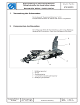
1. Komponenten des Bausatzes
Der Teilesatz 0510 590054 besteht aus den in der Zeichnung
abgebildeten Komponenten.
2. Anbau des Handtasters (mit Montagebeispielen)
Klasse 530, rechts montiert Klasse 510, links montiert
Achtung !
Der Taster ist so vormontiert, dass dieser an der rechten Seite des
Nähautomaten angebaut werden kann. Bei Anbau des Tasters an der
linken Seite des Nähautomaten, muss das Tastengehäuse auf der
anderen Seite des Winkels (Bestell-Nr.: 0510 492020) montiert werden.
Anbauanleitung für Handtaster
Teilesatz 0510 59 005 4
Fitting Instruction for hand switch
Kit 0510 59 005 4
Teile-Nr./ Part-No.:
0791 510701
Ausgabe/Edition:
02. 2005
Blatt: von
Sheet: 1 from 8
Printed in Federal Republic of Germany

2.1. Verlegung der Leitung
–
Entsprechend den Abbildungen vornehmen.
Die Abdeckhaube muss nachgearbeitet w erden (siehe Pfeil).
–
Mit einer Rundfeile etwas ausfeilen.
3. Elektrischer Anschluss des Handtasters
Alt (Bestell-Nr.: 9870 510007) Neu (Bestell-Nr.: 9870 510008)
Achtung !
Der bisherige Adapter (Bestell-Nr.: 9870 510007) entfällt und muss
durch den neuen Adapter (Bestell-Nr.: 9870 510008) ersetzt werden.
An diesem neuen Adapter müssen der Handtaster und das Fusspedal
angeschlossen werden.
Anbauanleitung für Handtaster
Teilesatz 0510 59 005 4
Fitting Instruction for hand switch
Kit 0510 59 005 4
Ausgabe/Edition:
02.2005
Teile-Nr./ Part-No.:
0791 510701
Blatt: von
Sheet: 2 from 8
Printed in Federal Republic of Germany
Pedal
Pedal
Handtaster

4. Aktivierung des Handtasters (ab Softwareversion A05)
Der Handtaster ist eine optionale Baugruppe und muss in der
Steuerung angemeldet werden.
–
Maschine einschalten.
–
Taste ”F” drücken.
–
Code ”25483” eingeben und mit ”OK” bestätigen.
–
Menü ”Maschine” anwählen und mit ”OK” bestätigen.
–
Menü ”Einrichtung” anwählen und mit ”OK” bestätigen.
–
Menü ”Ausstattung” anwählen und mit ”OK” bestätigen.
–
Menü ”Handtaster” anwählen und mit Taste “ OK” Menü aktivieren.
Mit der Taste ”é” Funktion auf ” EIN” stellen und mit ”OK ”
bestätigen.
–
Mit Taste ”ç” ins Menü “Einrichtungen” wechseln.
–
Mit Taste ”ç” ins Menü “Maschine” wechseln.
–
Mit Taste ”ç” ins Hauptmenü der Technikerebene wechseln.
Punkt 5. beachten.
5. Auswahl des Handtaster-Modus
– Im Hauptmenü der Technikerebene Menü “Benutzer” anwählen.
– Menü ”Handtaster” anwählen und mit Taste “ OK” Menü aktivieren.
Mit der Taste ”é” Funktion auf Modus ”A” oder ”B” stellen und mit
”OK” bestätigen
– Mit Taste ”ESC” ins Hauptmenü wechseln
Modus: A = Schnellstart
Taster 1: - Heben und Senken des Klammerfusses.
- Unterbrechung des Nähvorgangs.
- Abbruch des Nähvorgangs nach Unterbrechung.
Taster 2: - Wenn der Klammerfuss nicht abgesenkt ist, wird
er abgesenkt.
- Nähstart.
- Unterbrechung des Nähvorgangs.
- Fortsetzen des Nähvorgangs nach Unterbrechung.
Modus: B = Normal
Taster 1: - Heben und Senken des Klammerfusses.
- Unterbrechung des Nähvorgangs.
- Abbruch des Nähvorgangs nach Unterbrechung.
Taster 2: - Nähstart, wenn der Klammerfuss abgesenkt ist.
- Unterbrechung des Nähvorgangs.
- Fortsetzen des Nähvorgangs nach Unterbrechung.
Anbauanleitung für Handtaster
Teilesatz 0510 59 005 4
Fitting Instruction for hand switch
Kit 0510 59 005 4
Teile-Nr./ Part-No.:
0791 510701
Ausgabe/Edition:
02. 2005
Blatt: von
Sheet: 3 from 8
Printed in Federal Republic of Germany

Für Ihre Notizen:
Anbauanleitung für Handtaster
Teilesatz 0510 59 005 4
Fitting Instruction for hand switch
Kit 0510 59 005 4
Ausgabe/Edition:
02.2005
Teile-Nr./ Part-No.:
0791 510701
Blatt: von
Sheet: 4 from 8
Printed in Federal Republic of Germany

1. Components of the kit
The kit 0510 590054 consists of the components shown in the
drawing below.
2. Assembling the hand switch (incl. fitting demonstrations)
Class 530, fitted onto the right side Class 510, fitted onto to the left side
Attention !
The switch has been preassembled so as to be fitted onto the right
side of the sewing machine. If you want to fit the switch onto the left
side of the sewing machine, you must mount the key housing on the
other side of the bracket (part number: 0510 492020).
Anbauanleitung für Handtaster
Teilesatz 0510 59 005 4
Fitting Instruction for hand switch
Kit 0510 59 005 4
Teile-Nr./ Part-No.:
0791 510701
Ausgabe/Edition:
02. 2005
Blatt: von
Sheet: 5 from 8
Printed in Federal Republic of Germany

2.1. Laying of the cables
–
Proceed according to the pictures.
The covering cap must be reworked (see arrow).
–
Notchwitharattailfile.
3. Electrical connection of the hand switch
Old (Part number: 9870 510007) New (Part number: 9870 510008)
Attention !
The old adapter (part number: 9870 510007) is dropped and must
be replaced by the new adapter (part number: 9870 510008).
Hand switch and pedal must be connected to this new adapter.
Anbauanleitung für Handtaster
Teilesatz 0510 59 005 4
Fitting Instruction for hand switch
Kit 0510 59 005 4
Ausgabe/Edition:
02.2005
Teile-Nr./ Part-No.:
0791 510701
Blatt: von
Sheet: 6 from 8
Printed in Federal Republic of Germany
Pedal
Pedal
Hand switch

4. Activating the hand switch (from software version A05 onward)
The hand switch is an optional equipment and must be recognized by
the control.
–
Switch on the machine.
–
Press the key ” F”.
–
Enter the code ”25483” and confirm with ”OK”.
–
Select the menu ”Machine” and confirm with ”OK”.
–
Select the menu ”Settings” and confirm w ith ”OK”.
–
Select the menu ”Equipment” and confirm w ith ”OK”.
–
Select the menu ”Hand switch”and activate the menu by actuating
the “OK” key. By using the ”é” key, set the function to ”ON” and
confirm with ”OK”.
–
Go to the menu “Settings” by using the ”ç”key.
–
Switch to the menu “Machine” by using the ”ç”key.
–
Switch to the main menu of the technician level by using the ”ç”
key. Heed point 5.
5. Selecting the hand switch mode
– Select the menu “User” in the main menu of the technician level.
– Select the menu “hand switch” and activate the menu by actuating
the “OK” key. By using the ”é” key, s et the function to mode ”A”or
”B” and confirm with ”OK”.
– Switch to the main menu by actuating the ”ESC”key.
Mode: A = Quick start
Switch 1: - Lifting and lowering of the clamping foot.
- Interruption of the sewing process.
- Abortion of the s ewing process after the interruption.
Switch 2: - If the clamping foot is not lowered, it will be lowered.
-Sewingstart.
- Interruption of the sewing process.
- Continuing the sewing process after the interruption.
Mode: B = Regular
Switch 1: - Lifting and lowering of the clamping foot.
- Interruption of the sewing process.
- Abortion of the s ewing process after the interruption.
Switch 2: - Sewing starts w hen the clamping foot is lowered.
- Interruption of the sewing process.
- Continuing the sewing process after the interruption.
Anbauanleitung für Handtaster
Teilesatz 0510 59 005 4
Fitting Instruction for hand switch
Kit 0510 59 005 4
Teile-Nr./ Part-No.:
0791 510701
Ausgabe/Edition:
02. 2005
Blatt: von
Sheet: 7 from 8
Printed in Federal Republic of Germany

Notes:
Anbauanleitung für Handtaster
Teilesatz 0510 59 005 4
Fitting Instruction for hand switch
Kit 0510 59 005 4
Ausgabe/Edition:
02.2005
Teile-Nr./ Part-No.:
0791 510701
Blatt: von
Sheet: 8 from 8
Printed in Federal Republic of Germany
/