Peavey PV4 Power Amplifier Owner's manual
- Category
- Audio amplifiers
- Type
- Owner's manual

www.peavey.com
PV
®
4
Power Amplier
Operating
Manual

7
PV® 4
Power Amplifier
Congratulations on your purchase of the PV 4, a power amplifier designed for years of reliable, flawless operation under rigorous
use. This amplifier offers the sonic superiority and unsurpassed reliability for which Peavey is famous, while remaining surprising-
ly compact. Advanced technology and extensive protection circuitry allow operation with greater efficiency into difficult loads
and power conditions. The DDT™ (Distortion Detection Technique) circuitry ensures trouble-free operation into loads as low
as 2 ohms. DDT protects drivers and ensures that sonic integrity is maintained, even in extreme overload conditions. The PV 4’s
high-efficiency design uses tunnel-cooled heat sinks and variable-speed DC fans. This cooling topology maintains a lower over-
all operating temperature, resulting in longer output transistor life. For your safety, read the important precautions section, as
well as input, output and power connection instructions.
Although the PV 4 amplifier is simple to operate and housed in an ultra-strong steel chassis, improper use can be dangerous.
This amplifier is very highpowered and can put out high voltages and sizable currents at frequencies up to 30 kHz. Always use
safe operating techniques when operating this amplifier.
Before you send signal through your amplifier, it is very important to ensure that the product has the proper AC line
voltage supplied. You can find the proper voltage for your amp printed next to the IEC line (power) cord on the rear
panel of the unit. Each product feature is numbered. Refer to the front panel diagram in this manual to locate the
particular features next to its number.
Please read this guide carefully to ensure your personal safety as well as the safety of your amplifier.
FEATURES:
• Distortion Detection Technique (DDT)
• Line voltage selector switch
• Dual cooling fans
• 100 Hz Crossover
• Front panel LEDs: DDT, Signal,Thermal Protect and Power
• Switchable 2nd order 40Hz high pass filter
ENGLISH

8
SAVE THESE INSTRUCTIONS
1
Save the carton and packing materials!
Should you ever need to ship the
unit, use only the original factory
packing.
For replacement packaging, call Peavey
Customer Service Department directly.
2
Read all documentation before oper-
ating your equipment. Retain all doc-
umentation for future reference.
3
Follow all instructions printed on
unit chassis for proper operation.
4
Never hold a power switch or cir-
cuit breaker in the "ON" position if
it won’t stay there by itself!
5
Do not use the unit if the electrical
power cord is frayed or broken.
The power supply cords should be
routed so that they are not likely to
be walked on or pinched by items
placed upon or against them.
6
Always operate the unit with the AC
ground wire connected to the elec-
trical system ground. Precautions
should be taken so that the means
of grounding of a piece of equipment
is not defeated.
7
Damage caused by connection to
improper AC voltage is not covered
by any warranty. Mains voltage must
be correct and the same as that print-
ed on the rear of the unit.
8
Do not ground any hot (red) terminal.
Never connect a hot (red) output to
ground or to another hot (red) output!
9
Power down and disconnect units
from mains voltage before making
connections.
10
Do not drive the inputs with a sig-
nal level greater than that required
to enable equipment to reach full
output.
11
Do not run the output of any amplifier
channel back into another channel’s
input.
Do not parallel- or series-connect
an amplifier output with any other
amplifier output.
Peavey is not responsible for dam-
age to loudspeakers for any reason.
12
Do not connect the inputs or out-
puts of amplifiers to any other
voltage source such as a battery,
mains source, or power supply,
regardless of whether the ampli-
fier is turned on or off.
13
Connecting amplifier outputs to oscil-
loscopes or other test equipment
while the amplifier is in bridged mono
mode may damage both the amplifier
and test equipment!
14
Do not spill water or other liquids
into or on the unit, or operate the
unit while standing in liquid.
15
Do not block fan intake or exhaust
ports.
Do not operate equipment on a
surface or in an environment which
may impede the normal flow of air
around the unit, such as a bed,
rug, weathersheet, carpet or com-
pletely enclosed rack.
16
If the unit is used in an extremely
dusty or smoky environment the
unit should be periodically blown
free of foreign matter.
17
Do not use the unit near stoves,
heat registers, radiators or other
heat-producing devices.
18
The equipment power cord should be
unplugged from the outlet when left
unused for a long period of time.
Service Information
Do not remove the cover!
Removing the cover will expose you
to potentially dangerous voltages.
There are no user-serviceable parts
inside.
Equipment should be serviced by
qualified service personnel when:
A. The power supply cord or the plug
has been damaged.
B. The equipment has been exposed to
rain.
C. The equipment does not appear to
operate normally or exhibits a marked
change in performance.
D. The equipment has been dropped or
the enclosure damaged.
To obtain service:
contact your nearest Peavey
Service Center, Distributor, Dealer
or contact Peavey at 601.483.5365
USA or visit www.peavey.com for
additional information, email tech-
serve@peavey.com

9
Unpacking
Connecting Power
Upon unpacking, inspect the
amplifier. If you find any damage,
notify your supplier immediately.
Only the consignee may institute a
claim with the carrier for damage
incurred during shipping. Be sure
to save the carton and all packing
materials. Should you ever need to
ship the unit back to Peavey, one
of its offices, service centers or the
supplier, use only the original fac-
tory packing. If the shipping carton
is unavailable, contact Peavey to
obtain a replacement.
Because of the complexity of the de-
sign and the risk of electrical shock,
all repairs must be completed only
by qualified technical personnel.
Mounting
The PV® 4 amplifier will mount in
standard 19" racks. Rear mounting
ears are also provided for addition-
al support, which is recommended
in non-permanent installations like
mobile or touring sound systems.
The PV 4 amplifier power requirements
are rated at 1/8 power (typical music
conditions) and 1/3 power (extreme
music conditions). The maximum pow-
er current draw rating is limited only by
the front panel circuit breaker. Consult
the specifications in the Specification
section for figures on the current that
each amplifier will demand. Make sure
the mains voltage is correct and is the
same as that printed on the rear of the
amplifier. Damage caused by con-
necting the amplifier to improper AC
voltage is not covered by any warranty.
Therefore, be sure to set the line voltage
selector switch for the voltage in your
area.
Operating Precautions
Make sure the mains voltage is correct and the same as that printed on the rear of the amplifier. Damage caused by connect-
ing the amplifier to improper AC voltage is not covered by any warranty. See the Connecting Power section for more informa-
tion on voltage requirements.
Remember to have the gain controls turned down during power-up to prevent speaker damage if there is a high signal level at
the inputs. Whether you buy or make them, use good-quality connections, input cables and speaker cables, along with good
soldering technique, to ensure trouble-free operation. Most intermittent problems are caused by faulty cables.
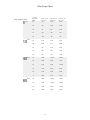
Consult the Wire Gauge Chart to determine proper gauges for different load impedances and cable lengths. Remember that
cable resistance robs amplifier power in two ways: power lost directly to resistance (I
2
R loss), and by increasing the total load
impedance, thereby decreasing the power demanded of the amplifier. Also, make sure the mode switch is correctly set for the
desired application. See Sections on Stereo, Parallel and Bridged Mono Mode for more information.
Installation
Always turn off and disconnect the amplifier
from mains voltage before making audio
connections. Also, as an extra precaution, turn
the attenuators down during power-up.
Cooling Requirements
The PV 4 amplifier uses a forced-air
cooling system to maintain a low,
consistent operating temperature.
Air is drawn into the amplifier by
fan(s) on the rear panel, courses
through the cooling fins of the tun-
nel-configured channel heat sink(s),
and then exhausts through the front
panel grille. If either heat sink gets
too hot, its sensing circuit will open
the output relay, disconnecting the
load from that particular channel.
The PV 4utilizes one common heat
sink and a single fan, but retains the
separate circuitry. NOTE: Maintain
an adequate air supply at the back
of the amplifier and enough space
around the front of the amplifier to
allow the cooling air to escape. If
the amp is rack mounted, do
not use doors or covers on the
front of the rack; the exhaust
air must flow without resistance.
If you are using racks with closed
backs, use fans on the rear rack panel
to pressurize the rack and ensure an
ample air supply.
Make certain that there is enough space around the front and rear of the amplifier to allow the heated air to
escape.
Suggestion: In racks with closed backs, allow at least one standard-rack-space opening for every mounted power
amplifier.

10
AC POWER SWITCH/CIRCUIT BREAKER
The PV® 4 amplifier has a combination AC switch/circuit breaker on the front panel. If the switch shuts off
during normal use, push it back to the ON position once. If it will not stay on, the amplifier needs
servicing.
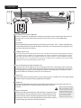
INDICATORS
The PV 4 amplifier features three front panel LED indicators per channel: DDT™, SIGNAL and POWER, plus
a shared Thermal Protect LED. These LED indicators inform the user of each channel’s operating status and
warn of possible abnormal conditions.
THERMAL PROTECT LED
This indicator illuminates when the thermal sensor on either heatsink reaches approximately 90 degrees
C, at which point, the amplifiers are muted while the fan remains on high speed. If this happens repeat-
edly, either reduce the load on the amplifier (detach one of the speakers), or supply additional cooling
to the amplifier, such as a fan. When rack mounting, it is helpful to leave 1 RU open above and below the
amplifier to prevent heat buildup from adjacent units.
DDT (DISTORTION DETECTION TECHNIQUE) LED
A channel’s DDT LED will light at the onset of clipping. If the LEDs are flashing quickly and intermit-
tently, the channel is just at the clip threshold. A steady, bright glow means the amp is clip limiting,
or reducing gain to prevent severely clipped waveforms from reaching the loudspeakers. See the
Distortion Detection Technique section for more information.
SIGNAL LED
This LED lights when its channel produces an output signal of about 1 volt RMS or more. This signal indicates
whether a signal is reaching and being amplified by the amplifier.
POWER LED
The Power LED indicates that its channel is operational. It lights under normal operation and remains on,
even when the channel is in Distortion Detection Technique or DDT gain
reduction.
INPUT ATTENUATORS
Whenever possible, set the attenuators fully clockwise to maintain optimum
system headroom. The input attenuator controls, located at the front panel
(one for channel A, one for channel B), adjust gain for their respective ampli-
fier channels in all modes. See the specifications at the end of this manual for
standard voltage gain and input sensitivity information.
Front Panel
1
2
3
4
5
6
3
2
4
5
6
1
When operating in the Bridged
Mode, both attenuators must
be in the same position so the
speaker load will be equally
shared between the channels.
See the section on Bridged
Mono operation for more
information and precautions.
THERMAL
PWR
6
16
20
23
26
29
32
6
16
20 23
26
29
32
SIG
DDT
TM TM
DDT
SIG PWR
PROTECT

11
Rear Panel
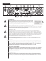
AC POWER INLET:
This is the receptacle for an IEC line cord, which provides AC power to the unit.
Connect the line cord to this connector to provide power to the unit. Damage
to the equipment may result if improper line voltage is used. Be sure to set the
line voltage selector (9) to the proper voltage for your area.
Never break o the ground pin on any equipment. It is provided for your safety.
If the outlet used does not have a ground pin, a suitable grounding adapter should be used and the third
wire should be grounded properly. To prevent the risk of shock or re hazard, always make sure that the
amplier and all associated equipment is properly grounded.
NOTE: FOR U.K. ONLY
As the colors of the wires in the mains lead of this apparatus may not correspond with the colored
markings identifying the terminals in your plug, proceed as follows: (1) The wire which is colored green
and yellow must be connected to the terminal which is marked by the letter E, or by the Earth symbol, or
colored green or green and yellow. (2) The wire which is colored blue must be connected to the terminal
which is marked with the letter N, or the color black. (3) The wire which is colored brown must be con-
nected to the terminal which is marked with the letter L, or the color red.
To avoid the risk of electrical shock, do not place ngers or any other objects into empty tube sockets
while power is being supplied to unit.
FAN GRILLE
A two-speed DC fan supplies cool air to the amplier. THIS INTAKE SHOULD NEVER BE BLOCKED! The fan
switches to high speed automatically when the unit requires additional cooling. At idle and cool, the fan
runs at low speed. The fan should never stop unless the amplier is switched OFF or the AC mains power
source is interrupted, or the thermal breaker in the transformer has tripped due to excess heating. The
thermal breaker in the transformer is self-resetting once the excess heat has dissipated.
LINE VOLTAGE SELECTOR SWITCH
The PV series power transformer is designed with two primaries that can be placed in series or parallel by
means of the line voltage selector switch. It is accessible by loosening one screw and rotating the trans-
parent guard out of the way. Please be sure this is set to the proper voltage for your area before turning
the amplier on for the rst time.
DUAL PRIMARY FUSE
In order to accommodate line voltage switching, the power transformer is designed with two prima-
ries that can be placed in series or parallel by means of the line voltage selector switch. Each primary is
individually fused, so there is no need to change fuse values when a dierent line voltage is selected. It
INPUT
BALANCED
INPUTS
SPEAKER OUTPUTS
MADE IN CHINA
115V 230V
BRIDGE
B
B
A
DDT
TM
STEREO
BRIDGE
ENABLE
DEFEAT
HIGH OUTHIGH OUT
CHANNEL A CHANNEL B
MOUNT IN RACK ONLY. INSTALLER SUR SUPPORT DE MONTAGE SEULEMENT
BRIDGE
T 25AL
250V
40 Hz
100 Hz
X-OVER
7 8 9 1311 1114 15 13 * 8
7
8
9
10
The power only breaks
one side of the AC mains.
Hazardous energy may be
present in the enclosure
when the power switch is in
the OFF position.
10 1612 1217

12
is important to use the fuse values specied on the rear panel. The fuses are provided to limit current to
the associated transformer primary winding, and protect it from overheating and possible destruction
due to fault conditions in the unit. The trip current values have been carefully chosen to allow reasonable
continuous power output performance, while still protecting the power transformer. These fuses should
not open unless there is a fault in the amplier circuitry that causes excessive mains current draw. How-
ever, abnormal conditions such as a short circuit on either or both channels, or continuous operation at
overload or clipping (especially into 2-ohm loads per channel or 4-ohm bridge load) can cause the fuses
to open. If this occurs, UNPLUG from the AC POWER source before replacing the fuses, after waiting a brief
period of time to allow the unit to cool down. Efforts should be made to correct the cause of the overload,
first by disconnecting one output at a time, and then one speaker at a time until the bad cable or damaged
speaker is isolated. If the fuses open instantly each time you attempt to turn the unit on, it should be taken
to a qualified Peavey Service Center for repair.
COMBO INPUT CONNECTOR
Input connections are made via the 3-pin XLR (pin 2+) or 6.3 mm plug “Combi” connectors on the rear panel
of the amplifier. The inputs are actively balanced. The input overload point is +28 dBu.
CONNECTING OUTPUTS
The PV4 has twist lock output connectors. Channel A and Channel B may be accessed individually with 2
conductor connectors, with (+) at terminal 1+ and (-) at terminal 1-. A 4 conductor twist lock may be used
on the channel A output, with channel B appearing at termials 2+ and 2-. For BRIDGE mode, use only the
channel A twist lock connector, and the (+) output is at terminal 1+, and the (-) output is at terminal 2+,
which is fed from Channel B output.
HIGH OUT JACKS
This 1/4” jack supplies high-frequency output signals from the activated crossover for patching to this
amplier and/or additional power amplier inputs. Unlike the low-frequency crossover output that is au-
tomatically routed to the associated channel, the high-frequency output signal must be patched to some
suitable input in order to complete the bi-amped system. This 1/4” jack also provides an unbalanced (tip/
sleeve) output to be patched with single-conductor shielded cables.
40 Hz SWITCH
This switch is used to activate the LOW CUT filter for the corresponding channel. It is a push-type switch, that
requires a small tool to activate. The IN position routes the input signals through the 40 Hz LOW CUT filter,
while the OUT position bypasses the filter. This filter will cut extremely low frequencies, protecting speakers
from the possibility of over-excursion. The filter low-frequency rolloff is 12 dB per octave. The LOW CUT filter
for each channel will function independently of the crossover function.
CROSSOVER SWITCH (100 Hz crossover)
This switch is used to activate the 40 Hz crossover for the corresponding channel. It is also a push-
type switch and requires a small tool to activate. The PV 4 offers two 100 Hz crossovers. These are
designed for use when a subwoofer is added to the system. With the switch IN, the input signals are
routed through the crossover and the low frequencies are automatically sent to the corresponding
channel. At the same time, the high frequencies are sent to the HIGH OUT (9) jack and must then be
patched to the INPUT of the other channel of this amplifier or to another amplifier input to complete
the bi-amped system. With the switch OUT, the crossover is defeated and the input signal is routed
directly to the respective power amp channel. The crossover frequency is fixed at 100 Hz and cannot
be changed. The crossover configuration is a four-pole Linkwitz-Riley approximation.
DDT™
Peavey’s patented DDT (Distortion Detection Technique) limiter circuit enables the sound technician
to maximize the performance of the amplifier/speaker combination by preventing the power ampli-
fier from clipping. When the onset of clipping is detected, the limiter engages to prevent damage to
Rear Panel
13
12
11
14
15
13

13
the loudpeakers and degradation of sound quality. For this reason, DDT should always be enabled.
BRIDGE MODE SELECTOR SWITCH
When a 2-channel amplier is operated in the Bridge mode, it is converted into a single-channel unit with a
power rating equal to the sum of the power rating for each channel, at a load of twice that of the single-chan-
nel rating. For example, the PV 4 is rated at 1250 Watts RMS per channel into 4 Ohms. The Bridge rating is
2800 Watts RMS into 8 Ohms. Bridge mode operation is accomplished by placing the MODE switch in the
BRIDGE position, and using a twist lock connector wired for bridge mode on the channel A output, and using
the CHANNEL A input. All CHANNEL B input functions are defeated and serve no purpose now. Bridge mode
operation can be used to drive sound distribution systems in very large public address applications. Another
common use for the Bridge mode is in subwoofer applications where very high power levels are required to
reproduce extremely low frequencies with adequate headroom. Such enclosures usually contain 2 or 4 loud-
speakers to handle the power levels involved. When using Bridge mode, the connected enclosure impedance
must be 4 or 8 Ohms — never below 4 Ohms.
CONNECTING INPUTS
Input connections are made via the 3-pin XLR (pin 2+) or 6.3 mm plug “Combi” connectors on the rear panel of
the amplifier. The inputs are actively balanced. The input overload point is +28 dBu.
CONNECTING OUTPUTS
The PV4 has twist lock output connectors. Channel A and Channel B may be accessed individually with 2 conduc-
tor connectors, with (+) at terminal 1+ and (-) at terminal 1-. A 4 conductor twist lock may be used on the channel
A output, with channel B appearing at terminals 2+ and 2-. For BRIDGE mode, use only the channel A twist lock
connector, and the (+) output is at terminal 1+, and the (-) output is at terminal 2+, which is fed from Channel B
output.
The input XLR connectors are wired according to standard practive for balanced interconnections, with pin 2 (+),
pin 3(-) and pin 1 ground. The TRS connectors are wired with Tip (+), Ring (-), and Sleeve ground.
*
17
Rear Panel

14
Operation Modes
For stereo (dual channel) operation, turn the amplifier off and set the mode select switches on the back panel to
the OUT (extended) position. In this mode, both channels operate independently of each other with their input
attenuators controlling their respective levels. For example, a signal at channel A’s input produces an amplified
signal at channel A’s output, while a signal at channel B’s input produces an amplified signal at channel B’s out-
put.
Stereo Operation
Both amplifier channels can be bridged together to make a very powerful single-channel monaural amplifier. Use
extreme caution when operating in bridged mode; potentially lethal voltage may be present at the output termi-
nals. To bridge the amplifier, depress the rear panel Bridge Mode switch (17) to the IN position. Direct the signal to
channel A’s input and connect the speakers across pin +1 and pin +2 of the channel A Speakon® output connector.
Only channel A’s input attenuator is active while in Bridged Mono mode.
Bridged Operation
Unlike the Stereo Mode, in which one side of each output is at ground, in the Bridged Mode
both sides are hot. Pin +1 is Channel A’s side, which is the same polarity as the input. The
minimum nominal load impedance in the Bridge Mode is 4 ohms, which is equivalent to
driving both channels at 2 ohms. Driving bridged loads of less than 4 ohms will activate
DDT™ circuitry, resulting in a loss of power and potential thermal overload.

15
Protection Features
Any time a channel is driven into hard, continuous clipping, the DDT circuit will automatically reduce the channel
gain to a level just slightly into clipping, guarding the speakers against the damaging high power continuous
square waves that may be produced. Situations that may activate the DDT circuit include uncontrolled feedback,
oscillation, an improper equipment setting or malfunction upstream from the amplifier. Normal program
transients will not trigger the DDT, only steady, excessive clipping will. The DDT LED will flash on peaks when DDT
is active, and will flash brightly with clipping when DDT is disabled.
Distortion Detection Technique™ (DDT)
Internal fans keep the amplifier operating well within its intended temperature range under all normal conditions.
If either channel's heat sink temperature reaches 90°C, both channels of the amplifier will shut down until it has
cooled. During this time, the THERMAL PROTECT LED will light up and the fans will continue to run at high speed.
Thermal Protection
The PV®4 amplifier incorporates several circuits to protect both themselves and loudspeakers under virtually any
situation. Peavey has attempted to make the amplifiers as foolproof as possible by making them immune to short
and open circuits, mismatched loads, DC voltage, and overheating. If a channel goes into the Distortion Detection
Technique or DDT™ gain reduction mode, the speaker load remains connected, but clipping percentage is instant-
ly reduced. DC voltage on the output, excessive subsonic frequencies or thermal overload will cause the channel’s
output to disconnect from the speaker load until the problem is corrected or the amplifier cools down.
Short Circuit
If an output is shorted, the overcurrent protection circuit will engage and reduce the output of the amplifier to
protect the output devices. Solid red DDT LEDs and dim signal LEDS is an indication of a short circuit and should
be investigated immediately. To find the cause of the overload, start by disconnecting one output at a time, and
then one speaker at a time until the bad cable or damaged speaker is isolated.
DC Voltage Protection
If a DC or subsonic voltage is present at the outputs, a crowbar circuit engages to prevent loudspeaker damage.

16
Protection Features
At power-up, the amplifier stays in mute mode with outputs disconnected for several seconds while the power
supplies charge and stabilize. When power is removed, the mute mode engages so that no thumps or pops are
heard.
Turn-On/Turn-Off Protection

17
Safety
All loudspeakers have electrical, thermal and physical limits that must be observed to prevent damage or failure.
Too much power, low frequencies applied to high frequency drivers, severely clipped waveforms and DC voltage
can all be fatal to cone and compression drivers. The Peavey PV®4 amplifier automatically protects speakers from
DC voltages and subsonic signals. For more information, see the section on Protection Features. Mid- and high-fre-
quency speakers, especially compression drivers, are highly susceptible to damage from overpowering, clipped
waveforms or frequencies below their rated pass band. Be extremely careful that the low and mid bands of an elec-
tronic crossover are connected to the correct amplifiers and drivers and not accidentally connected to those for
a higher frequency band. The amplifier’s clipping point is its maximum peak output power and can deliver more
power than many speakers can safely handle. Be sure the peak power capability of the amplifier is not excessive
for your speaker system.
To ensure that the speakers never receive excessive power and that the amplifier never clips, use a properly adjust-
ed external limiter (or a compressor with a ratio of 10:1 or higher) to control power output. In systems with active
electronic crossovers, use one for each frequency band. The clip limiter will automatically limit the duration of
continuous square waveforms applied to the speakers. Some speaker systems are packaged with processors that
have power limiting circuits and should not require additional external limiting.
Do not drive any low-frequency speaker enclosure with frequencies lower than its own tuned frequency. The
reduced acoustical damping could cause a ported speaker to exceed its mechanical limits and permanently
deform the voice coil, even when driven with comparatively low power. Consult the speaker system specifications
to determine its frequency limits.
Speaker Protection
A PV4 amplifier requires no routine maintenance and should never need any internal adjustment during its
lifetime. Your PV4 amplifier is very powerful and can be potentially dangerous to loudspeakers and humans
alike. It is your responsibility to read the Important Precautions section in the front of this manual and to make
sure that the amplifier is installed, wired and operated properly. Many loudspeakers can be easily damaged
or destroyed by overpowering, especially with the high power available from a bridged amplifier. Read the
Speaker Protection section and always be aware of the speaker’s continuous and peak power capabilities.
Amplifier Maintenance and User Responsibility

18
PV
®
4 Specications
Features and specifications subject to change without notice.
Rated Power Bridge 8 ohms
2800 watts @ 1 kHz at 1% THD
Rated Power (2 x 4 ohms)
1400 WPC @ 1 kHz at 1% THD
Rated Power (2 x 8 ohms)
880 WPC @ 1kHz 1% THD
Rated Power (1 x 4 ohms)
1560 watts @ 1kHz 1% THD
Rated Power (1 x 8 ohms)
950 watts @ 1kHz 1% THD
Minimum Load Impedance
4 ohms
Maximum RMS Voltage
97 volts ; 194 volts in bridge mode
Frequency Response
10 Hz- 30 kHz; +0, -2 dB at 1 watt
Input CMRR
>- 55 dB @ 1 kHz
Voltage Gain
x40 (32 dB)
Crosstalk
> -55 dB @ 1 kHz at rated power @ 8 ohms
Hum and Noise
-88 dB, “A” weighted reference to rated power @
8 ohms
Slew Rate
>12V / uS
Damping Factor (8 ohms)
>400:1 @ 20 Hz-2.5 kHz
Input Sensitivity (x40)
+ 8dBu / 1.95V RMS w/ 2x 4 ohm load
Input Impedance
10k ohms, balanced
Power consumption @ 1/8
power
750 watts with 2 x 4 ohm load
Cooling
Two rear panel temperature dependent variable
speed 80 mm DC fans
Controls
2 front panel attenuators, rear panel Mode switches
Indicator LEDs
2 DDT (Distortion Detection Technique), 2 Signal
presence, 2 Active Status, 1 Thermal Protect
Protection
Thermal, DC, turn-on bursts, subsonic, incorrect
loads
Connectors
Per channel, Combi XLR & 6.3 mm phone input,
twist lock output, 15 amp IEC mains connector
Dimensions
88.9 mm x 482.6 mm x 381mm + 31.8 for rear
support ears and connectors
(3.5" x 19" x 15" + 1.25")
Net Weight
19.5 kg (43 lbs)
Gross Weight
20.6 kg (45.5 lbs)
All power measurements made at 120 VAC, power transformer cold. 2 ohm power is time limited by magnetic circuit breaker.

19
All power measurements made at 120 VAC, power transformer cold. 2 ohm power is time limited by magnetic circuit breaker.
wire gauge power loss into power loss into power loss into
(AWG) 8 Ω load (%) 4 Ω load (%) 2 Ω load (%)
18
16
14
12
10
.79
.50
.31
.20
.125
1.58
1.00
.62
.40
.25
3.16
2.00
1.24
.80
.50
5
feet
18
16
14
12
10
1.58
1.00
.62
.40
.25
3.16
2.0
1.25
.80
.50
6.32
4.00
2.50
1.60
1.00
10
feet
18
16
14
12
10
8
8.00
4.00
2.50
1.60
1.00
.625
12.60
8.00
5.00
3.20
2.00
1.25
25.20
1.60
10.00
6.40
4.00
2.50
40
feet
16
14
12
10
8.00
5.00
3.20
2.00
16.00
10.00
6.40
4.00
32.00
20.00
12.80
8.00
80
feet
cable length (in feet)
standard
Wire Gauge Chart


Logo referenced in Directive 2002/96/EC Annex IV
(OJ(L)37/38,13.02.03 and defined in EN 50419: 2005
The bar is the symbol for marking of new waste and
is applied only to equipment manufactured after
13 August 2005
www.peavey.com
Warranty registration and information for U.S. customers available online at
www.peavey.com/warranty
or use the QR tag below
Features and specications subject to change without notice.
Peavey Electronics Corporation 5022 Hartley Peavey Drive Meridian, MS 39305 (601) 483-5365 FAX (601) 486-1278
-
 1
1
-
 2
2
-
 3
3
-
 4
4
-
 5
5
-
 6
6
-
 7
7
-
 8
8
-
 9
9
-
 10
10
-
 11
11
-
 12
12
-
 13
13
-
 14
14
-
 15
15
-
 16
16


Peavey PV4 Power Amplifier Owner's manual
- Category
- Audio amplifiers
- Type
- Owner's manual
Ask a question and I''ll find the answer in the document
Finding information in a document is now easier with AI
Related papers
-
Peavey CS 4000 Power Amplifier Owner's manual
-
-
-
-
-
 Peavy CS 1400 Power Amplifier User manual
-
-
-
-

Other documents
-
Pyle PMSA20 User manual
-
Kicx SP 4.80AB Instructions Manual
-
Crest Audio Pro 8200 User manual
-
Yamaha P2075 Owner's manual
-
AMC A Series User manual
-
Altronix ALSD1 Datasheet
-
Cerwin-Vega CV-5000 User manual
-
Lab.gruppen LAB 300 User manual
-
 Active Thermal Management 00-301-03 Datasheet
-
Fender 2235 Power Amplifier Owner's manual
