
The SCW-1D is a wall-mount, Decora
®
style
speaker volume control. It connects
between the speaker-level output of an
amplifier, speaker selector, etc. and a pair
of speakers. A perfect application for the
SCW-1D is adjusting the volume of
remotely located speakers.
The SCW-1D adjusts the volume of speakers
connected to it by attenuating the amplifier
signal. Niles volume controls use autoformers
instead of L-pads for the volume controlling
element. The autoformers assure minimal
internal power dissipation with virtually no
power wasted as heat.
B
LENDING H IGH F IDELITY AND A RCHITECTURE
®
SCW-1D
STEREO WALL-MOUNT VOLUME CONTROL
Niles Audio Corporation 12331 S.W. 130 Street Miami, Florida 33186 Tel: (305) 238-4373 Fax: (305) 238-0185
©1999 Niles Audio Corporation. All rights reserved. Niles, the Niles logo and Blending High Fidelity and Architecture are registered trademarks of Niles
Audio Corporation. Decora is a registered trademark of Leviton Manufacturing Co., Inc. Because Niles continuously strives to improve its products, Niles
reserves the right to change product specifications without notice. Printed in the USA 11/96 DS00172A
•
A 10-position control for a broad range
of adjustment
•
Transformers made of the highest quality
grain-oriented silicon steel to provide
20-20,000 Hz (± 2dB) frequencyresponse
andsuperb powerhandling (60watts)
•
Dual set-screw knob to prevent
accidental removal
•
100% electrical and acoustical testing
for frequency response, distortion, and
power handling
•
10 year parts and labor warranty
•
Available in four designer colors
Introduction
Audio Power Handling
100 Watts/channel peak music power
60 Watts/channel continuous power
Mounting
In-wall, fits into most 18 cubic inch single-
gang electrical boxes at least 2-3/4” deep,
Decora-style faceplate
Wiring Requirements
Individual runs of 2-conductor speaker
wire, 14-22 gauge
Unit Dimensions
1-5/8" wide x 2-7/8" high
Face Plate Dimensions
Decora faceplate;
2-3/4” wide x 4-1/2” high
Depth Behind Plate
2-1/4”
Specifications
Niles Audio Corporation (“NILES”) warrants its
passive products (those not requiring AC or battery
power) to the original purchaser to be free of manu-
facturing defects in material and workmanship for a
period of ten years from date of purchase.
This Warranty is subject to the following additional
conditions and limitations. The Warranty is void and
inapplicable if NILES deems that the product has
been used or handled other than in accordance
with the instructions provided by the manufacturer,
including but not limited to damage caused by
accident, mishandling, improper installation, abuse,
negligence, or normal wear and tear, or any defect
caused by repair to the product by anyone other
than NILES or an authorized NILES dealer.
To obtain warranty service, take the unit to the
nearest authorized NILES dealer, who will test the
product and if necessary, forward it to NILES for
service. If there are no authorized NILES dealers in
your area, you must write to NILES and include
your name, model and serial number of your unit,
along with a brief description of the problem. A fac-
tory Return Authorization Number will be sent to
you. DO NOT RETURN ANY UNIT WITHOUT FIRST
RECEIVING WRITTEN AUTHORIZATION AND
SHIPPING INSTRUCTIONS FROM NILES.
If the above conditions are met, the purchaser’s
sole remedy shall be to return the product to
NILES, in which case NILES will repair or replace, at
its sole option, the defective product without
charge for parts or labor. NILES will return a unit
repaired or replaced under warranty by shipping
same by its usual shipping method from the factory
(only) at its expense within the United States of
America. THERE ARE NO OTHER WARRANTIES,
INCLUDING WITHOUT LIMITATION, EITHER
EXPRESS OR IMPLIED WARRANTIES OF MER-
CHANTABILITY OR FITNESS FOR A PARTICULAR
PURPOSE, WITH RESPECT TO THE PRODUCT.
REPAIR OR REPLACEMENT AS PROVIDED
UNDER THIS WARRANTY IS THE EXCLUSIVE
REMEDY OF THE CONSUMER/PURCHASER.
NILES SHALL NOT BE RESPONSIBLE FOR ANY
INCIDENTAL OR CONSEQUENTIAL DAMAGES
EXCEPT TO THE EXTENT PROVIDED (OR PROHIB-
ITED) BY APPLICABLE LAW.
Some states do not allow the exclusion or limitation
of incidental or consequential damages, so the
above limitation may not apply to you. This warran-
ty gives you specific legal rights, and you may also
have other rights which vary from state to state.
For the name of your nearest authorized NILES
dealer contact:
NILES AUDIO CORPORATION
P.O. BOX 160818, Miami, Florida 33116.
Limited Warranty
Features and Benefits
Niles Audio Corporation
1. Make sure the amplifier or
receiver is OFF and set the
volumetominimum.
2. Set the SCW-1D volume
to maximum (fully clock-
wise).
3. If you are using a Niles
speaker selector system, locate
the ON/OFF button which
corresponds to the speaker
pair you wish to play. Set it to
the ON position.
4. Turn on the amplifier or
receiver and select a source,
such as tuner or CD player.
5. Slowly turn up the ampli-
fier or receiver volume and
set it to a comfortable (not
maximum) listening level.
Be careful not to overdrive
or “clip” your amplifier. If
the sound becomes muddy
or distorted, you have
reached the limit of your
amplifier’s volume capabili-
ty and should quickly
reduce the volume to avoid
damaging your speakers.
6. Adjust the volume of the
speakers to the desired lis-
tening level by using the
SCW-1D. If all the speaker
pairs in your system are
equipped with Niles volume
controls, you can leave the
amplifier or receiver volume
set at one position and use
the Niles controls exclusively.
7. You can turn off the
speakers by turning the
knob on the SCW-1D com-
pletely counter-clockwise, or
by pressing the ON/OFF
button on your speaker
selector.
Operation

The SCW-1D is a Decora-
style module designed to
use “Decora-style” face-
plates and mounting hard-
ware. Decora faceplates (up
to 6-gang) with color-
matched plate screws are
available from your Niles
dealer.
P-Ring and Electrical
Boxes
The mounting depth of the
SCW-1D is 2-3/8”. When
installed, the unit extends
1-7/8” behind the sheet-
rock wall (assuming 1/2”
sheetrock). For installation,
you must choose between a
standard light switch plaster
ring (p-ring) or a standard
18 cubic inch (or larger)
electrical box. Suitable p-
rings and electrical boxes
are available from your Niles
dealer or a local electrical
supply company. Using the
p-ring is best because it
gives you unobstructed
access to the full depth of
the wall. In some instances,
the use of a p-ring may be
inappropriate, such as in a
retro-fit (existing construc-
tion) installation, or when
building codes require that
wall devices be enclosed in
electrical boxes. Contact
your local building code
and inspection department
if unsure.
Type of Speaker Wire
For most applications, we
recommend you use 16 or
18 gauge, stranded copper
speaker wire for the SCW-1D
and connections. For wiring
runs longer than 80 feet, 14
gauge wire is recommend-
ed. Using speaker wire larger
than 14 gauge for SCW-1D
and connections is not rec-
ommended — the wire may
not fit into the connectors.
Never use solid-core, alu-
minum or “Romex” type
wire with the SCW-1D.
When running speaker wires
inside walls, most states and
municipalities in the U.S.
specify that you must use a
special type of speaker wire.
Usually, the requirement is
that the wire has a specific
“CL” fire rating, such as
“CL-2” or “CL-3”. Consult
your Niles dealer, building
contractor, or local building
and inspection department
if unsure about which type
of wire is best for your
application.
DO NOT INSTALL THE
SCW-1D INTO ELECTRI-
CAL BOXES WITH 110
VOLT DEVICES.
Some states or municipali-
ties allow devices such as
the SCW-1D to be installed
into the same electrical box
as 110 volt devices, provid-
ed a “low-voltage parti-
tion” is used between the
devices. We do not recom-
mend this. Speaker wires
can act as an “antenna” for
electrical noise. Locating
speaker wires too close to a
light switch or dimmer may
cause a “popping” or
“buzzing” sound to be
heard through the speak-
ers. If you must locate an
SCW-1D near electrical
devices, install it in a sepa-
rate metal electrical box,
ground the box to the elec-
trical system ground, and
route the speaker wires sev-
eral feet away from the
electrical wiring.
If you are installing the
SCW-1D into an existing
wall, take time to consider
any possible obstructions
which may be hidden inside
the wall, such as wood and
metal studs; electrical, tele-
phone wire or other types
of wiring; plumbing; con-
duit; old wall safes; etc.
1. Install the electrical box or
p-ring in the usual manner.
2. Run all the necessary
wiring to the SCW-1D.
Label the wires for future
reference.
3. Make the connections to
the SCW-1D. Strip 1/4” of
insulation from the end of
each wire. Tightly twist the
end of each wire until there
are no frayed ends. Insert
each wire into the appropri-
ate hole on the connector
blocks; secure the wiring to
the connectors by tighten-
ing the small connector
screws. Be certain that
proper phasing is obser-
ved—connect the positive
terminals on the SCW-1D to
the positive terminals on
the amplifier and speakers;
the negative terminals on
the SCW-1D to the negative
terminals on the amplifier
and speakers. See Figure 1.
4. Secure the SCW-1D to
the electrical box or p-ring.
Insert the 1-1/4” long device
screws into the oblong-
shaped screw holes on the
top and bottom of the
SCW-1D. Note that the
oblong shape of the screw
holes allow you to position
the SCW-1D so that it is ver-
tical. Position the SCW-1D
so that the screws are
aligned with the threaded
holes in the electrical box or
p-ring. Tighten the screws
using a philips screwdriver.
DO NOT OVER-TIGHTEN. In
some instances, you may
need to loosen these screws
several turns to allow the
SCW-1D to fit flush with the
Decora cover plate.
5. Use the shorter plate
screws to fasten the Decora
faceplate to the SCW-1D.
DO NOT OVER-TIGHTEN
THE PLATE SCREWS OR
YOU MAY DAMAGE THE
FACEPLATE. Line up all the
screws in the same direction
for a finished look. NOTE:
Certain “old work” or
“retro-fit” boxes, such as
the Carlon B225R, have a
plastic “lip” which interferes
with the Decora faceplate
screws. This lip prevents
you from being able to
tighten the screws com-
pletely. To make the clear-
ance necessary for these
screws, you must remove
the parts of the lip causing
interference. There are two
ways to accomplish this:
1. Drill through the lip of
the box at the screw points.
2. Cut notches into the lip
with a pair of diagonal cutters.
Installation Considerations Installation
SCW-1D
Mounting Locations
Convenient mounting loca-
tions for the SCW-1D are:
•
Near entryways or exits
•
Near a desk
•
At your bedside
•
Close to a telephone
•
Near other wall controls
(a) Electrical Box
(b) Speaker Wire
(c) SCW-1D Volume Control
(d) Knob
(e) Device Screws
(f) Decora Faceplate
(g) Faceplate Screws
a
c
e
e
f
d
g
g
b
b
Figure 1
Input
Receiver
Output
Speaker Pair
-
 1
1
-
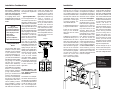 2
2


Ask a question and I''ll find the answer in the document
Finding information in a document is now easier with AI
Related papers
Other documents
-
Niles Audio VCS50 User manual
-
-
 MCM Custom Audio 50-14835 Operating instructions
-
 DIGITECH Audio AC-1401 User manual
-
-
-
-
Welch Allyn 6702W Series User manual
-
-

