RAD Data comm ASM-60 User manual
- Category
- Networking
- Type
- User manual

A
SM-60
Installation and Operation Manual
4
-Wire Symmetrical VDSL
Modem


ASM-60
4-Wire Symmetrical VDSL Modem
Installation and Operation Manual
Notice
This manual contains information that is proprietary to RAD Data Communications Ltd. ("RAD"). No
part of this publication may be reproduced in any form whatsoever without prior written approval by
RAD Data Communications.
Right, title and interest, all information, copyrights, patents, know-how, trade secrets and other
intellectual property or other proprietary rights relating to this manual and to the ASM-60 and any
software components contained therein are proprietary products of RAD protected under international
copyright law and shall be and remain solely with RAD.
ASM-60 is a registered trademark of RAD. No right, license, or interest to such trademark is granted
hereunder, and you agree that no such right, license, or interest shall be asserted by you with respect
to such trademark.
You shall not copy, reverse compile or reverse assemble all or any portion of the Manual or the
ASM-60. You are prohibited from, and shall not, directly or indirectly, develop, market, distribute,
license, or sell any product that supports substantially similar functionality as the ASM-60, based on or
derived in any way from the ASM-60. Your undertaking in this paragraph shall survive the termination
of this Agreement.
This Agreement is effective upon your opening of the ASM-60 package and shall continue until
terminated. RAD may terminate this Agreement upon the breach by you of any term hereof. Upon
such termination by RAD, you agree to return to RAD the ASM-60 and all copies and portions thereof.
For further information contact RAD at the address below or contact your local distributor.
International Headquarters
RAD Data Communications Ltd.
24 Raoul Wallenberg St.
Tel Aviv 69719 Israel
Tel: 972-3-6458181
Fax: 972-3-6498250
E-mail: [email protected]
U.S. Headquarters
RAD Data Communications Inc.
900 Corporate Drive
Mahwah, NJ 07430 USA
Tel: (201) 529-1100, Toll free: 1-800-444-7234
Fax: (201) 529-5777
E-mail: [email protected]
© 1989–2002 RAD Data Communications Ltd. Publication No. 145-200-11/02

Limited Warranty
RAD warrants to DISTRIBUTOR that the hardware in the ASM-60 to be delivered hereunder shall be
free of defects in material and workmanship under normal use and service for a period of twelve (12)
months following the date of shipment to DISTRIBUTOR.
If, during the warranty period, any component part of the equipment becomes defective by reason of
material or workmanship, and DISTRIBUTOR immediately notifies RAD of such defect, RAD shall have
the option to choose the appropriate corrective action: a) supply a replacement part, or b) request
return of equipment to its plant for repair, or c) perform necessary repair at the equipment's location.
In the event that RAD requests the return of equipment, each party shall pay one-way shipping costs.
RAD shall be released from all obligations under its warranty in the event that the equipment has been
subjected to misuse, neglect, accident or improper installation, or if repairs or modifications were
made by persons other than RAD's own authorized service personnel, unless such repairs by others
were made with the written consent of RAD.
The above warranty is in lieu of all other warranties, expressed or implied. There are no warranties
which extend beyond the face hereof, including, but not limited to, warranties of merchantability and
fitness for a particular purpose, and in no event shall RAD be liable for consequential damages.
RAD shall not be liable to any person for any special or indirect damages, including, but not limited to,
lost profits from any cause whatsoever arising from or in any way connected with the manufacture,
sale, handling, repair, maintenance or use of the ASM-60, and in no event shall RAD's liability exceed
the purchase price of the ASM-60.
DISTRIBUTOR shall be responsible to its customers for any and all warranties which it makes relating
to ASM-60 and for ensuring that replacements and other adjustments required in connection with the
said warranties are satisfactory.
Software components in the ASM-60 are provided "as is" and without warranty of any kind. RAD
disclaims all warranties including the implied warranties of merchantability and fitness for a particular
purpose. RAD shall not be liable for any loss of use, interruption of business or indirect, special,
incidental or consequential damages of any kind. In spite of the above RAD shall do its best to provide
error-free software products and shall offer free Software updates during the warranty period under
this Agreement.
RAD's cumulative liability to you or any other party for any loss or damages resulting from any claims,
demands, or actions arising out of or relating to this Agreement and the ASM-60 shall not exceed the sum
paid to RAD for the purchase of the ASM-60. In no event shall RAD be liable for any indirect, incidental,
consequential, special, or exemplary damages or lost profits, even if RAD has been advised of the
possibility of such damages.
This Agreement shall be construed and governed in accordance with the laws of the State of Israel.

General Safety Instructions
The following instructions serve as a general guide for the safe installation and operation of
telecommunications products. Additional instructions, if applicable, are included inside the manual.
Safety Symbols
This symbol may appear on the equipment or in the text. It indicates
potential safety hazards regarding product operation or maintenance to
operator or service personnel.
Danger of electric shock! Avoid any contact with the marked surface while
the product is energized or connected to outdoor telecommunication lines.
.
Protective earth: the marked lug or terminal should be connected to the building
protective earth bus.
Some products may be equipped with a laser diode. In such cases, a label
with the laser class and other warnings as applicable will be attached near
the optical transmitter. The laser warning symbol may be also attached.
Please observe the following precautions:
• Before turning on the equipment, make sure that the fiber optic cable is
intact and is connected to the transmitter.
• Do not attempt to adjust the laser drive current.
• Do not use broken or unterminated fiber-optic cables/connectors or look
straight at the laser beam.
• The use of optical devices with the equipment will increase eye hazard.
• Use of controls, adjustments or performing procedures other than those
specified herein, may result in hazardous radiation exposure.
ATTENTION: The laser beam may be invisible!
Always observe standard safety precautions during installation, operation and maintenance of this
product. Only qualified and authorized service personnel should carry out adjustment, maintenance or
repairs to this product. No installation, adjustment, maintenance or repairs should be performed by
either the operator or the user.
Warning
Warning

Handling Energized Products
General Safety Practices
Do not touch or tamper with the power supply when the power cord is connected. Line voltages may
be present inside certain products even when the power switch (if installed) is in the OFF position or a
fuse is blown. For DC-powered products, although the voltages levels are usually not hazardous,
energy hazards may still exist.
Before working on equipment connected to power lines or telecommunication lines, remove jewelry
or any other metallic object that may come into contact with energized parts.
Unless otherwise specified, all products are intended to be grounded during normal use. Grounding is
provided by connecting the mains plug to a wall socket with a protective earth terminal. If an earth lug
is provided on the product, it should be connected to the protective earth at all times, by a wire with a
diameter of 18 AWG or wider. Rack-mounted equipment should be mounted only in earthed racks
and cabinets.
Always make the ground connection first and disconnect it last. Do not connect telecommunication
cables to ungrounded equipment. Make sure that all other cables are disconnected before
disconnecting the ground.
Connection of AC Mains
Make sure that the electrical installation complies with local codes.
Always connect the AC plug to a wall socket with a protective ground.
The maximum permissible current capability of the branch distribution circuit that supplies power to
the product is 16A. The circuit breaker in the building installation should have high breaking capacity
and must operate at short-circuit current exceeding 35A.
Always connect the power cord first to the equipment and then to the wall socket. If a power switch is
provided in the equipment, set it to the OFF position. If the power cord cannot be readily
disconnected in case of emergency, make sure that a readily accessible circuit breaker or emergency
switch is installed in the building installation.
Connection of DC Mains
Unless otherwise specified in the manual, the DC input to the equipment is floating in reference to the
ground. Any single pole can be externally grounded.
Due to the high current capability of DC mains systems, care should be taken when connecting the DC
supply to avoid short-circuits and fire hazards.
DC units should be installed in a restricted access area, i.e. an area where access is authorized only to
qualified service and maintenance personnel.
Make sure that the DC supply is electrically isolated from any AC source and that the installation
complies with the local codes.
The maximum permissible current capability of the branch distribution circuit that supplies power to
the product is 16A. The circuit breaker in the building installation should have high breaking capacity
and must operate at short-circuit current exceeding 35A.
Before connecting the DC supply wires, ensure that power is removed form the DC circuit. Locate the
circuit breaker of the panel board that services the equipment and switch it to the OFF position. When
connecting the DC supply wires, first connect the ground wire to the corresponding terminal, then the
positive pole and last the negative pole. Switch the circuit breaker back to the ON position.
A readily accessible disconnect device that is suitably rated and approved should be incorporated in
the building installation.

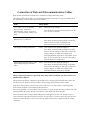
Connection of Data and Telecommunications Cables
Data and telecommunication interfaces are classified according to their safety status.
The following table lists the status of several standard interfaces. If the status of a given port differs from
the standard one, a notice will be given in the manual.
Ports Safety Status
V.11, V.28, V.35, V.36, RS-530,
X.21, 10 BaseT, 100 BaseT,
Unbalanced E1, E2, E3, STM, DS-2,
DS-3, S-Interface ISDN, Analog voice
E&M
SELV Safety Extra Low Voltage:
Ports which do not present a safety hazard. Usually
up to 30 VAC or 60 VDC.
xDSL (without feeding voltage),
Balanced E1, T1, Sub E1/T1
TNV-1 Telecommunication Network Voltage-1:
Ports whose normal operating voltage is within the
limits of SELV, on which overvoltages from
telecommunications networks are possible.
FXS (Foreign Exchange Subscriber) TNV-2 Telecommunication Network Voltage-2:
Ports whose normal operating voltage exceeds the
limits of SELV (usually up to 120 VDC or telephone
ringing voltages), on which overvoltages from
telecommunication networks are not possible. These
ports are not permitted to be directly connected to
external telephone and data lines.
FXO (Foreign Exchange Office), xDSL
(with feeding voltage), U-Interface
ISDN
TNV-3 Telecommunication Network Voltage-3:
Ports whose normal operating voltage exceeds the
limits of SELV (usually up to 120 VDC or telephone
ringing voltages), on which overvoltages from
telecommunication networks are possible.
Always connect a given port to a port of the same safety status. If in doubt, seek the assistance of a
qualified safety engineer.
Always make sure that the equipment is grounded before connecting telecommunication cables. Do
not disconnect the ground connection before disconnecting all telecommunications cables.
Some SELV and non-SELV circuits use the same connectors. Use caution when connecting cables.
Extra caution should be exercised during thunderstorms.
When using shielded or coaxial cables, verify that there is a good ground connection at both ends. The
earthing and bonding of the ground connections should comply with the local codes.
The telecommunication wiring in the building may be damaged or present a fire hazard in case of
contact between exposed external wires and the AC power lines. In order to reduce the risk, there are
restrictions on the diameter of wires in the telecom cables, between the equipment and the mating
connectors.

To reduce the risk of fire, use only No. 26 AWG or larger telecommunication line cords.
Pour réduire les risques s’incendie, utiliser seulement des conducteurs de
télécommunications 26 AWG ou de section supérieure.
Some ports are suitable for connection to intra-building or non-exposed wiring or cabling only. In such
cases, a notice will be given in the installation instructions.
Do not attempt to tamper with any carrier-provided equipment or connection hardware.
Electromagnetic Compatibility (EMC)
The equipment is designed and approved to comply with the electromagnetic regulations of major
regulatory bodies. The following instructions may enhance the performance of the equipment and will
provide better protection against excessive emission and better immunity against disturbances.
A good earth connection is essential. When installing the equipment in a rack, make sure to remove all
traces of paint from the mounting points. Use suitable lock-washers and torque. If an external
grounding lug is provided, connect it to the earth bus using braided wire as short as possible.
The equipment is designed to comply with EMC requirements when connecting it with unshielded
twisted pair (UTP) cables. However, the use of shielded wires is always recommended, especially for
high-rate data. In some cases, when unshielded wires are used, ferrite cores should be installed on
certain cables. In such cases, special instructions are provided in the manual.
Disconnect all wires which are not in permanent use, such as cables used for one-time configuration.
The compliance of the equipment with the regulations for conducted emission on the data lines is
dependent on the cable quality. The emission is tested for UTP with 80 dB longitudinal conversion loss
(LCL).
Unless otherwise specified or described in the manual, TNV-1 and TNV-3 ports provide secondary
protection against surges on the data lines. Primary protectors should be provided in the building
installation.
The equipment is designed to provide adequate protection against electro-static discharge (ESD).
However, it is good working practice to use caution when connecting cables terminated with plastic
connectors (without a grounded metal hood, such as flat cables) to sensitive data lines. Before
connecting such cables, discharge yourself by touching earth ground or wear an ESD preventive wrist
strap.
FCC-15 User Information
This equipment has been tested and found to comply with the limits of the Class A digital device,
pursuant to Part 15 of the FCC rules. These limits are designed to provide reasonable protection
against harmful interference when the equipment is operated in a commercial environment. This
equipment generates, uses and can radiate radio frequency energy and, if not installed and used in
accordance with the Installation and Operation manual, may cause harmful interference to the radio
communications. Operation of this equipment in a residential area is likely to cause harmful
interference in which case the user will be required to correct the interference at his own expense.
Caution
Attention

Canadian Emission Requirements
This Class A digital apparatus meets all the requirements of the Canadian Interference-Causing
Equipment Regulation.
Cet appareil numérique de la classe A respecte toutes les exigences du Règlement sur le matériel
brouilleur du Canada.
Warning per EN 55022 (CISPR-22)
This is a class A product. In a domestic environment, this product may cause
radio interference, in which case the user will be required to take adequate
measures.
Cet appareil est un appareil de Classe A. Dans un environnement résidentiel, cet
appareil peut provoquer des brouillages radioélectriques. Dans ces cas, il peut
être demandé à l’utilisateur de prendre les mesures appropriées.
Dieses ist ein Gerät der Funkstörgrenzwertklasse A. In Wohnbereichen können
bei Betrieb dieses Gerätes Rundfunkströrungen auftreten, in welchen Fällen der
Benutzer für entsprechende Gegenmaßnahmen verantwortlich ist.
Warning
Avertissement
Achtung

ASM-60 with IR-ETH/QH Interface Module
Installation Instructions for
Compliance with EMC Requirements
To comply with electromagnetic compatibility requirements, use a shielded cable (STP) for connecting
a 10/100BaseT LAN to the RJ-45 connector of the IR-ETH/QH interface module.

Declaration of Conformity
Manufacturer's Name: RAD Data Communications Ltd.
Manufacturer's Address: 24 Raoul Wallenberg St.
Tel Aviv 69719
Israel
declares that the product:
Product Name: ASM-60
conforms to the following standard(s) or other normative document(s):
EMC: EN 55022: 1998 Information technology equipment, radio disturbance
characteristics, limits and methods of measurement.
EN 50024: 1998 Information technology equipment, Immunity characteristics,
limits and methods of measurement.
Safety: EN 60950: 2000 Safety of information technology equipment.
Supplementary Information:
The product herewith complies with the requirements of the EMC Directive 89/336/EEC, the Low
Voltage Directive 73/23/EEC and the R&TTE Directive 99/5/EC for wired equipment. The product was
tested in a typical configuration.
Tel Aviv, 29th October, 2002
Haim Karshen
VP Quality
European Contact: RAD Data Communications GmbH, Otto-Hahn-Str. 28-30,
85521 Ottobrunn-Riemerling, Germany


Installing ASM-60 1
Quick Start Guide
Installation of ASM-60 should be carried out only by an experienced technician. If
you are familiar with ASM-60, use this guide to prepare the units for operation.
1. Installing ASM-60
Setting the Internal Switches
To set internal switches:
1. Disconnect the power cord from the power source.
2. Slide the blue side panel forward to detach it from the case.
3. Unscrew the two screws located on the bottom panel at the rear end of the
unit.
4. Separate the two halves of the ASM-60 case by lifting the top cover at the end
of the unit and sliding it forward.
5. Set the internal switches of the Ethernet interface board (IR-ETH, IR-ETH/QH
or IR-IP).
Connecting the Interfaces
1. Connect the line to the RJ-45 rear panel connector.
2. Connect the DTE to the appropriate rear panel connector.
3. Connect the control terminal to the front CONTROL DCE connector.
Connecting the Power
• Connect the AC power to the ASM-60 modem.
The PWR indicator turns on.

Quick Start Guide ASM-60 Installation and Operation Manual
2 Configuring ASM-60
2. Operating ASM-60
Normal Indications
The table below shows the correct status of the indicators a few seconds after
power-up.
Indicator Status
PWR ON
TD Depends on DTE data transmission
RD Depends on DTE data transmission
RTS Depends on DTE RTS signal status
DCD Depends on remote modem data transmission
TEST OFF
ALM OFF
SYNC A/SYNC B Green or red, depending on remote modem data
transmission
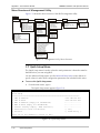
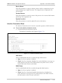
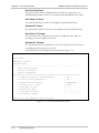
3. Configuring ASM-60
Configure ASM-60 to the desired operation mode via an ASCII terminal using the
embedded management software. Configuration of the ASM-60 modem includes
selection of a data rate.
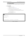
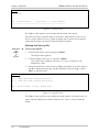
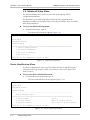
Selecting the Data Rate
To select the data rate:
1. From the Configuration menu, type 1.
The Data Rate menu appears.
2. Select the data rate by typing the number corresponding to the desired value
and then type 2 to save the changes.
Main Menu
↓ 1
Configuration
↓ 1
Data Rate

ASM-60 Installation and Operation Manual i
Contents
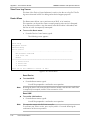
Chapter 1. Introduction
1.1
Overview..................................................................................................................... 1-1
Versions................................................................................................................................1-1
Application ...........................................................................................................................1-1
Features................................................................................................................................1-2
1.2
Physical Description..................................................................................................... 1-3
1.3
Functional Description................................................................................................. 1-4
1.4
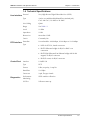
Technical Specifications............................................................................................... 1-5
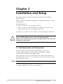
Chapter 2. Installation and Setup
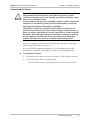
2.1
Site Requirements and Prerequisites ............................................................................ 2-1
2.2
Package Contents ........................................................................................................ 2-2
2.3
Installation and Setup .................................................................................................. 2-2
Performing the Internal Settings.............................................................................................2-2
Connecting the Interfaces .....................................................................................................2-3
Connecting the Power ..........................................................................................................2-5
Chapter 3. Operation
3.1
Front Panel Indicators .................................................................................................. 3-1
3.2
Operating ASM-60 ...................................................................................................... 3-2
Turning On ASM-60 .............................................................................................................3-2
Normal Operation ................................................................................................................3-2
Normal Indications ...............................................................................................................3-2
Turning Off ASM-60 .............................................................................................................3-2
Chapter 4. Management from a Terminal
4.1
Preparing for the Control Session ................................................................................. 4-1
Control Port Interface Characteristics.....................................................................................4-1
Preparing Terminal ...............................................................................................................4-1
4.2
Navigating the Management Menus............................................................................. 4-2
Terminal Management Menus...............................................................................................4-3
4.3
Starting the Control Session ......................................................................................... 4-3
4.4
Configuring ASM-60 .................................................................................................... 4-4
Selecting the Data Rate.........................................................................................................4-4
4.5
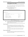
Displaying the ASM-60 System Information ................................................................. 4-5
Displaying the ASM-60 Status ...............................................................................................4-6
4.6
Resetting ASM-60 ........................................................................................................ 4-7

Table of Contents
ii ASM-60 Installation and Operation Manual
Chapter 5. Diagnostics
5.1
Error Detection............................................................................................................ 5-1
Power-Up Self-Test...............................................................................................................5-1
Front-Panel LEDs ..................................................................................................................5-1
Alarms ..................................................................................................................................5-1
5.2
Displaying the VDSL Performance Diagnostics ............................................................. 5-3
5.3
Running the Diagnostic Tests ....................................................................................... 5-5
Running the LEDs Test ..........................................................................................................5-5
Appendix A. IR-ETH Interface Module
Appendix B. IR-ETH/QH Interface Module
Appendix C. IR-IP Interface Module

Table of Contents
ASM-60 Installation and Operation Manual iii
List of Figures
1-1. Typical ASM-60 Application .................................................................................................. 1-1
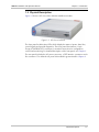
1-2. 3D View of ASM-60 .............................................................................................................. 1-3
1-3. ASM-60 Block Diagram ......................................................................................................... 1-4
2-1 Rear Panel of ASM-60 with HSSI Interface.............................................................................. 2-3
3-1 ASM-60 Front Panel ............................................................................................................... 3-1
4-1. ASM-60 Management Software ............................................................................................. 4-3
4-2. Main Menu ........................................................................................................................... 4-4
4-3. Configuration Menu .............................................................................................................. 4-4
4-4. Data Rate Menu .................................................................................................................... 4-5
4-5. Display Menu........................................................................................................................ 4-5
4-6. Status Screen......................................................................................................................... 4-6
4-7. Reset Menu........................................................................................................................... 4-7
5-1. Alarms Screen ....................................................................................................................... 5-2
5-2. Log File Screen...................................................................................................................... 5-2
5-3. VDSL Performance Screen..................................................................................................... 5-4
List of Tables
1-1. Typical ASM-60 Ranges......................................................................................................... 1-2
2-1 Line Connector Pinout ........................................................................................................... 2-3
2-2. HSSI Interface Connector Pinout ........................................................................................... 2-4
3-1. LED Indicators...................................................................................................................... 3-1
3-2. ASM-60 Indicator Status ........................................................................................................ 3-2
4-1. Control Port Control Signals................................................................................................... 4-2
5-1. ASM-60 Alarms ..................................................................................................................... 5-3
5-2. ASM-60 Performance Monitoring Parameters ........................................................................ 5-4

Table of Contents
iv ASM-60 Installation and Operation Manual

Overview 1-1
Chapter 1
Introduction
1.1 Overview
ASM-60 is a VDSL (Very High-bitrate Digital Subscriber Line) modem handling
high data rates. ASM-60 supports HSSI DTE interface, and several Ethernet
interface modules, which allow LAN-to-LAN connectivity using VDSL technology.
Working in full duplex over 4-wire link, the modem can be configured to operate
at the data rates of up to 10.240 Mbps.
Versions
ASM-60 is available in the two following versions:
• ASM-60/CO, for the central office deployment
• ASM-60/CPE, for customer premises deployment.
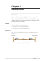
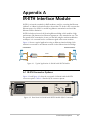
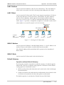
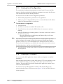
Application
Figure 1-1 shows a typical application for ASM-60, connecting the LANs over a
4-wire line.
ASM-60/CO ASM-60/CPE
LAN LAN
Central Office Customer Premises
4-wire
2.0 km (1.2 miles)
Figure 1-1. Typical ASM-60 Application

Chapter 1 Introduction ASM-60 Installation and Operation Manual
1-2 Overview
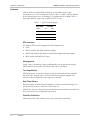
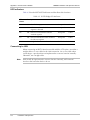
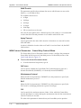
Features
ASM-60 utilizes the QAM VDSL technology to extend the range of data
transmission over 4-wire 24 AWG line up to 2.0 km (1.2 miles). ASM-60 operates
at the following data rates: 4.096 Mbps, 6.144 Mbps and 10.24 Mbps. Table 1-1
lists typical ASM-60 ranges over 24 AWG STP Cat. 5 wire.
Table 1-1. Typical ASM-60 Ranges
Data Rate 24 AWG
(Mbps) km miles
4.096 2.0 1.2
6.144 2.0 1.2
10.24 1.8 1.1
DTE Interface
The ASM-60 DTE interface supports the following interfaces:
• HSSI
• IR-ETH module with built-in Ethernet bridge
• IR-ETH/QH module with built-in Fast Ethernet bridge and VLAN support
• IR-IP module with built-in IP router.
Management
Setup, control, monitoring of status and diagnostics can be performed using an
ASCII terminal connected to the ASM-60 async DCE control port.
Test Capabilities
ASM-60 performs an extensive self-test at start-up. During the self-test, ASM-60
checks its CPU, internal framer, DTE and interfaces and power supplies. The
self-test results are displayed on the supervisory terminal.
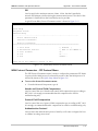
Real Time Alarms
Real time alarms provide real time information on system status indicating loss of
synchronization on line A and line B, DCD status etc.
ASM-60 also features a log file that stores all alarms and events that occurred in the
unit. These alarms can be displayed and cleared.
Statistics Collection
ASM-60 stores the VDSL statistics for the line performance monitoring.
Page is loading ...
Page is loading ...
Page is loading ...
Page is loading ...
Page is loading ...
Page is loading ...
Page is loading ...
Page is loading ...
Page is loading ...
Page is loading ...
Page is loading ...
Page is loading ...
Page is loading ...
Page is loading ...
Page is loading ...
Page is loading ...
Page is loading ...
Page is loading ...
Page is loading ...
Page is loading ...
Page is loading ...
Page is loading ...
Page is loading ...
Page is loading ...
Page is loading ...
Page is loading ...
Page is loading ...
Page is loading ...
Page is loading ...
Page is loading ...
Page is loading ...
Page is loading ...
Page is loading ...
Page is loading ...
Page is loading ...
Page is loading ...
Page is loading ...
Page is loading ...
Page is loading ...
Page is loading ...
Page is loading ...
Page is loading ...
Page is loading ...
Page is loading ...
Page is loading ...
Page is loading ...
Page is loading ...
Page is loading ...
Page is loading ...
Page is loading ...
Page is loading ...
Page is loading ...
Page is loading ...
Page is loading ...
Page is loading ...
Page is loading ...
Page is loading ...
Page is loading ...
Page is loading ...
Page is loading ...
Page is loading ...
Page is loading ...
Page is loading ...
Page is loading ...
Page is loading ...
Page is loading ...
Page is loading ...
Page is loading ...
Page is loading ...
Page is loading ...
-
 1
1
-
 2
2
-
 3
3
-
 4
4
-
 5
5
-
 6
6
-
 7
7
-
 8
8
-
 9
9
-
 10
10
-
 11
11
-
 12
12
-
 13
13
-
 14
14
-
 15
15
-
 16
16
-
 17
17
-
 18
18
-
 19
19
-
 20
20
-
 21
21
-
 22
22
-
 23
23
-
 24
24
-
 25
25
-
 26
26
-
 27
27
-
 28
28
-
 29
29
-
 30
30
-
 31
31
-
 32
32
-
 33
33
-
 34
34
-
 35
35
-
 36
36
-
 37
37
-
 38
38
-
 39
39
-
 40
40
-
 41
41
-
 42
42
-
 43
43
-
 44
44
-
 45
45
-
 46
46
-
 47
47
-
 48
48
-
 49
49
-
 50
50
-
 51
51
-
 52
52
-
 53
53
-
 54
54
-
 55
55
-
 56
56
-
 57
57
-
 58
58
-
 59
59
-
 60
60
-
 61
61
-
 62
62
-
 63
63
-
 64
64
-
 65
65
-
 66
66
-
 67
67
-
 68
68
-
 69
69
-
 70
70
-
 71
71
-
 72
72
-
 73
73
-
 74
74
-
 75
75
-
 76
76
-
 77
77
-
 78
78
-
 79
79
-
 80
80
-
 81
81
-
 82
82
-
 83
83
-
 84
84
-
 85
85
-
 86
86
-
 87
87
-
 88
88
-
 89
89
-
 90
90


RAD Data comm ASM-60 User manual
- Category
- Networking
- Type
- User manual
Ask a question and I''ll find the answer in the document
Finding information in a document is now easier with AI
Related papers
-
RAD Data comm ASM-20 User manual
-
-
-
-
-
-
-
-
-
Other documents
-
Morningstar EMC-1 Quick start guide
-
Black Box PRO SWITCHING SYSTEM User manual
-
 RAD Digital B- Battery Torque Wrench User manual
-
ADTRAN NxT1 HSSI/V-35 User manual
-
Nortel Networks BCM200 User manual
-
DPS Telecom NetGuardian 216 User manual
-
Avaya BCM1000 Installation and Maintenance Manual
-
-
Nokia 100Base-T User manual
-
