Page is loading ...

EAGLE 2
INSTRUCTIONS
Welcome to the sport of Radio Control flying!
Congratulations on selecting the Mark II Eagle--today’s top trainer and all around sport model. Many new improvements
make the Mark II even easier to build and fly than past versions of the Eagle.
It may seem a bit early to speak of flying, but your successful first flight begins right here. Before starting assembly,
please read carefully through this instruction booklet. It won’t take that long, and building your model and installing your
equipment will seem easier, since you will know where you are going.
WARNING
While this aircraft is an excellent first choice for novice pilots, a radio-controlled model is not a toy and is not intended for
persons under 16 years old. Keep this kit out of the reach of younger children, as it contains parts that could be danger-
ous. A radio-controlled model is capable of causing serious bodily injury and property damage. It is the buyer’s respon-
sibility to build this kit correctly and to properly install the motor, radio, and all other equipment. Test and fly the finished
model only in the presence and with the assistance of another experienced R/C flyer. the model must always be operat-
ed and flown using great care and common sense, as well as in accordance with the Safety Code of the Academy of
Model Aeronautics (5151 Memorial Drive, Muncie, IN 47302), 1-800-435-9262). We suggest you join the AMA and
become properly insured prior to flying this model. Also, consult with the AMA or your local hobby dealer to find an
experienced instructor in your area. Per the Federal Communications Commission, you are required to use only those
radio frequencies specified “for Model Aircraft”.
CARL GOLDBERG PRODUCTS, LTD.
PT #2036 10/02
©Copyright 1978

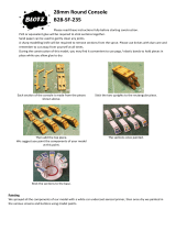
NECESSARY TOOLS AND SUPPLIES.
MISCELLANEOUS RUBBER BANDS,
PLUS A BOX OF #64 RUBBER
BANDS
WAXED PAPER
MODELING KNIFE AND RAZOR
BLADES
SANDPAPER (ASSORTED GRITS,
INCLUDING COARSE (80), MEDIUM
(150) AND FINE (220-320)
SANDING BLOCK
“T” PINS (at least 75)
FLAT BUILDING BOARD(24”x60”)
SOFT ENOUGH TO PUSH PINS INTO
ELECTRIC DRILL AND ASSORTED
DRILL BITS (1/16”, 1/8” & 3/16”)
SCISSORS
SMALL SCREWDRIVER (1/8” x 3/16”
BLADE TIP)
ALLEN WRENCHES (1/16” & 7/64”)
MASKING TAPE
LONG NOSE PLIERS
COVERING IRON AND HEAT GUN
OPTIONAL: CGP ENGINE TEST STAND, PROP BAL-
ANCER, PROP/GLO-PLUG WRENCH, CGP HINGE
SLOTTING KIT.
1
ITEMS NEEDED TO COMPLETE THIS KIT
1 RADIO GUIDANCE SYSTEMS (3 to 4-CHANNEL
REQUIRED)
1 .29 to .45 2-CYCLE OR .40 to .60 4-CYCLE R/C
ENGINE
PROPELLER, FUEL TANK & TUBING TO SUIT
ENGINE
1 2-1/4” CGP SNAP-ON SPINNER
1 2-1/4” WHEEL*
2 2-1/2” WHEELS*
1 2 OZ. BOTTLE CA GLUE
1 CAACCELERATOR
1 20 MINUTE EPOXY
1 TUB BALSA TINTED CGP FILLER
2 ROLLS IRON ON COVERING
1 1/2” x 8” x 12” CGP FOAM RUBBER
1/16” x 1/4” WING SEATING TAPE
FUEL PROOF PAINT
OPTIONAL: ITEMS FOR BOLT-ON WING OPTION
DESCRIBED LATER IN BOOK, 4” SILICONE TUBING
FOR EXHAUST EXTENSION; ART ACRYLIC PAINT FOR
PILOT FIGURE, 1/4” CGP ULTRASTRIPE FOR DETAIL-
ING, CGP SCUFF GUARD TO PROTECT TAIL FROM
SCRATCHES.
* Use next larger size wheel if flying from tall grass.

2
Your model was designed to use three or four- channel
radio control equipment. In flight, the model is primarily controlled
by using the ailerons and elevator (see sketch at left). One radio
channel controls the ailerons. This is the primary turn control - it
rolls the model. Another channel operates the elevator which con-
trols pitch (climbing, level flight and descent). The third channel is
for the engine throttle and controls the engine speed. A fourth
channel is used for rudder which assists the ailerons for turning.
The new R/C flyer will probably only use the rudder for steering the
model on the ground. Note: for three-channel flying, ailerons are
not used and the rudder becomes the primary turn control.
Radio sets are battery powered with either dry cells
(small flashlight type batteries) or more reliable rechargeable
nickel-cadmium batteries (ni- cads). Sets powered with ni-cads
come equipped with a recharging unit, and are more expensive
than dry-cells sets. However, if you intend to do a lot of flying, the
cost of routinely replacing worn out dry cell batteries will be much
greater than the higher initial cost of a re-chargeable ni-cad radio
system; something to consider. Many of the radio systems now
available feature “servo reversing” switches which allow you to
reverse the response of the servo. This feature simplifies radio
installation and is a worthwhile consideration when selecting a
radio system. You may find radios with more sophisticated fea-
tures such as dual rates, exponential and control mixing, etc.
These features are not needed for general sport flying, and are
typically used my more advanced flyers.
When selecting a radio, remember that there are many
radio frequencies available. Not all of these frequencies can be
legally used to operate model airplanes. Tell your dealer that you
want a radio with a model “Airplane” frequency.
WARNING: Per the Federal Communications Commission there
is only one group of frequencies designated for radio control air-
craft use. According to the law, it is your responsibility to use the
designated aircraft frequencies to operate your model airplane.
SELECTING RADIO CONTROL EQUIPMENT
DIGITAL PROPORTIONAL
RADIO CONTROL
ONE OF MANY SYSTEMS AVAILABLE,
PLEASE SEE YOUR LOCAL DEALER OR
CLUB FOR ADVICE ON SELECTING
YOUR RADIO.

3
ENGINE, PROPELLER & ACCESSORIES
Your plane flies well using any 2-cycle engine size from
.35 to .45, or 4-cycle engine .45 to .61. The numbers .35 to .45
refer to the amount of space the piston moves through inside the
cylinder of the engine. This space is called displacement; larg-
er displacement generally means more power. If you live in a hot
climate, or your flying field is approximately 3,000 feet or more
above sea level, you should stay with a .45 engine. It’s a good
idea to select an engine that is popular at the flying field, so that
if you have any engine problems, other modelers will be familiar
with the engine and be able to help.
The propeller size must be matched to the engine. For
example, a .35 may use a 9” diameter prop while a .45 can use a
10” prop. Refer to the propeller chart below for recommended
propeller sizes. It’s wise to buy a few spare props, as everyone
breaks them occasionally, and particularly often when learning
to fly.
Balancing your propeller helps to protect your radio
from the damaging effects of the market. We recommend sand-
ing the heavy blade on the curved face, out near the tip, rather
than on the flat face. Try to maintain the normal airfoil curvature.
Avoid scratches which may cause the prop to break. Never
carve or cut a prop near the hub for any reason (such as to fit a
spinner).
A 2¼” CGP Snap-On Spinner is recommended for the
Eagle. It is a rugged precision molded spinner which does not
require any special mounting nuts or screws. Although a spin-
ner helps reduce the chance of injury from the rotating prop,
extreme caution always must be used when the engine is run-
ning.
Refer to the Prop & Fuel Tank Chart shown here for the
correct size fuel tank for your particular engine. There are many
sizes and brands available. Assemble your fuel tank according
to the manufacturer’s instructions.
As with other precision equipment, a new engine
should be "broken-in" to enhance performance and extend its
life. Breaking-in usually consists of running the engine with a
"rich" fuel mixture and at lower RPMs until all the moving parts
get to "know each other better." This can be done with the
engine mounted in the model or securely clamped into a CGM
Engine Test Stand or similar device. Refer to your engine's
operating manual for the recommended break-in procedure and
follow it carefully.
FIELD EQUIPMENT
The following equipment will be needed at the flying field to start
your engine, make adjustments, and clean your model after fly-
ing.
FLIGHT BOX: Something sturdy in which to carry your
equipment. CGP's SuperTote or ProTote are economical, easy to
build, and pack lots of utility into little space. They hold fuel,
transmitter, starter & battery, as well as many tools, in a bal-
anced load that is easy to carry.
STARTING BATTERY AND GLO-PLUG CLIP: A 1-1/2
volt battery is required to heat your engine's glo-plug for start-
ing. Wires connect the glo-plug clip to the battery. Because
engine starting draws a lot of electric power from the battery,
rechargeable ni-cad batteries are recommended. Although they
cost more initially, they are more economical in the long run
than frequently replacing dry-cell batteries.
FUEL: For best engine performance, use the fuel recommend-
ed by your engine's manufacturer. 2 and 4-cycle engines require
different fuel blends. Ask your dealer to recommend a good
quality 5-10% Nitro fuel.
FUEL PUMP: Needed to transfer fuel from the fuel can to the
model's fuel tank. A simple squeeze-type bulb will do for small
tanks, whereas manual crank or electric pumps fill larger tanks
more quickly.
FUEL LINE: Have about 3 feet of silicone fuel line to make
connections between the fuel pump, the fuel can, and the
model's fuel tank.
EXTRA PROPS: Experts always have a few spares on hand,
so flying doesn't have to stop due to a broken propeller.

4
INTRODUCTION
USING THIS INSTRUCTION MANUAL
Before you start gluing and sanding, take some time
becoming familiar with the plans and looking through this entire
instruction booklet. It is designed to guide you through the con-
struction process step by step, so build in the order given in this
book. Balancing, setting up and flying the model are also cov-
ered.
Like a full-size airplane, the EAGLE II is built from
basic structures (stabilizer, fin, wing, etc.), which are then
assembled into the complete airplane. Special procedures or
comments will usually be explained before a step, so you will be
prepared. If a step begins with a statement like “Note,”
“Warning,” or “Important,” it is a good idea to read through the
step before doing it.
A check-off box appears at the beginning of each step.
Check these boxes as you build, so you can tell at a glance
what steps you have completed. Some steps are repeated and
must be marked twice, as in the case of the left and right wing
panel.
HOW TO READ THE PLAN
There is one plan sheet in this kit, showing the
Fuselage (Body), the Wing, and the Tail Parts. Everything on
the plan is drawn to full-size and shape and shows how the fin-
ished parts fit together.
The plan is drawn to show the model completely
assembled, but as a result, the areas inside or underneath are
covered up, making it hard to understand how these parts fit
together. Therefore, for clarity, some parts are drawn with hid-
den lines, others with breakaway views, and some are entirely
removed from the structure and shown separately.
For example, on the fuselage, the left side of the com-
pleted model has been removed to show the details inside.
Sometimes a surface is broken away to reveal the detail behind
or underneath. Dashed lines indicate details that are hidden
behind or under another part of the surface.
FUSELAGE DRAWN WITH LEFT
SIDE REMOVED TO REVEAL
INNER FUSELAGE DETAILS
THE WING IS SHOWN CUT
THROUGH AT THE CENTER-
THIS IS A “SECTION” VIEW
Dashed lines show
a part “Hidden
behind the fuel tank.
Fuselage side “Breakaway” view
to show how switch is mounted
The model is made from four varieties of wood: balsa,
bass, birch, and various plywoods. Each kind of wood has its
own characteristic end grain pattern (as viewed from the end)
which has been drawn on the plan. You can easily use these
end grain patterns to identify what kind of wood is shown for
that part, if you are in doubt.
HOW TO USE THE PLAN
The plan is used in several ways. The wings, stabilizer,
and fin are assembled directly over the plan. Each wood part is
matched over its corresponding location printed on the plan and
pinned in place. To prevent ruining your plan from gluing your
wings, etc. to it, cover the area you are working on with waxed
paper.
The paper the plan is printed on can expand or contract
slightly with changes in temperature or humidity. Because of this, a
preformed part such as the notched wing trailing edge may not
exactly match the plan. This is no problem, as slight deviations in
the outline or size will not noticeably affect flight performance.
Because the fuselage plugs together and is self-aligning,
it is not built directly over the plan. As you assemble the fuselage,
you will find the plan helpful in identifying parts and how things fit
together.
The plan also shows the installation of a typical radio, battery and
all remaining equipment and hardware needed to complete the
model. By referring to the examples shown, you should be able to
install your own radio, etc., even if it is not the same as what is
shown on the plan.
IDENTIFYING PARTS
Parts for the wing are bundled together; likewise, parts for the tail
assembly are also grouped. Die-cut plywood and balsa sheets of
common sizes are bundled together, so they are less likely to be
damaged during shipping and handling. The various screws,
hinges, and fittings are packaged in plastic bags.
PREPARING FOR ASSEMBLY
Set a flat, warp-free pinning board on your work bench. Any mate-
rial that accepts pins, such as insulation board, soft plywood, or dry-
wall (sheet rock) will work. Important: any warps or bends in the pin-
ning board will result in wings or tail surfaces that are also warped
or bent, making your model more difficult to fly. Make sure that the
pinning board is flat by laying a straight edge across it. You may be
able to correct a warped board by shimming its low areas.
Position the area of the plan (such as the stabilizer) on which you
are going to build over the pinning board and tape it in place so the
plan lays flat and wrinkle free.
Place a sheet of waxed paper over the work area to prevent
SUPER JET from sticking to your plan and ruining it.
CONSTRUCTION TIPS
In assembling your model, the following tips will prove helpful.
IMPORTANT: ALWAYS READ A FEW STEPS AHEAD. This will
alert you to coming instructions and will help you plan accordingly.
You may find it convenient to empty all of the small parts
from the hardware bags into a common container, such as a mar-
garine tub. This will help you find items quickly.
Punch out only the die-cut (D/C) parts you need as you
proceed. This will help you keep track of parts, especially the small
ones.
After completing each section of the aircraft, you may want
to go back and re-glue the joints, just in case some area has been
missed. Be careful not to use too little glue, which will leave the
model weak, or too much glue, which can make the model heavy.
Properly glued joints are important to the overall strength of the
model. SUPER JET™ is recommended for most parts of the
assembly, although JET Epoxy may be used when more time is
needed for careful placement.

5
The EAGLE II was designed for fast assembly using SUPER
JET™ glue, which is a specially formulated cyanoacrylate adhe-
sive CA that can firmly glue the plywood, hardwood, and balsa
used in your model.
ADHESIVES
WARNING
Never use water THIN type CA glue for general construction of your
model, especially for gluing plywood and hardwood parts. Thin CA's do
not adequately bond these areas.
Although most of you construction should be done with SUPER JET™,
there are times, such as when you are installing the stabilizer and fin
on the fuselage and want more set-up time for careful alignment and
positioning, when you may wish to use SLOW JET™. And occasional-
ly, you may also wish to use JET EPOXY™ for added strength.
Aliphatic resin glue or similar water-based glues can also be used, but
they will add to the assembly time because they dry so much more
slowly than SUPER JET™ -
GLUING TECHNIQUES
SUPER JET™ is strongly recommended for most building tasks
because, when pressed into a very thin layer, it sets almost instantly.
After the initial bond, SUPER JET™ continues to strengthen. However,
because of SUPER JET's™ quick set-up, you must be careful to read
instruction thoroughly, as you will have only moments for positioning of
parts. Be sure to trial fit pats together before gluing.
SUPER JET™ is used in two general ways. One is to apply SUPER
JET™ to one part and then press the two parts to be glued together. Or,
you can position parts in contact and then run SUPER JET™ into the
joint. As it seems into the joint, it will leave a slight reinforcing filler. If
you don't see a slight fillet, the CAhas soaked into the wood edges and
a second coat is needed.
SUPER JET™ sets up a bit slower with plywood and hardwood, so hold
such parts together a little longer than you would for balsa. Comer fil-
lets take even longer to dry because there is not a thin layer.
The tendency is for all CA glues to set slower on harder woods or when
in a thick layer. Corner fillets also take a while longer to dry. To speed
up such slow drying joints, use JET SET™, an accelerator for all brands
of CA glue. JET SET™ bridges greater gaps, speeds up slow bonds,
and provides string glue joint fillets
Epoxy glues come in two parts which need to be mixed before using.
When buying epoxy, check to see how long the glue takes to set We
recommend either JET 6 MINUTE EPOXY™ or JET 20 MINUTE
EPOXY™. Disposable wood strips, cotton swabs, cheap stiff bristle
brushes or acid brushed from auto stores make good applicators.
Because epoxy is so thick, it is easy to apply too much. Use sparingly,
especially when assembling the fin, stabilizer, and wings.
CAUTION
Some people may experience an allergic reaction when exposed to
fumes from CA glue or epoxy. As with paints, thinners, and solvents, it
is always important to use glues only where there is adequate ventila-
tion to carry fumes away. A fan is recommended.
Also, special care must be taken when using CA, as it will bond skin as
well as other surfaces. JET DE-SOLV™ is a CA solvent which removes
hardened glue from fingers and softens glued joints for repositioning.
When using CA, protective eye-wear and care in keeping the glue away
from the face is highly recommended. If CAdoes happen to get into the
eye, hold lid open and seek immediate medical attention.
MAJOR COMPONENTS BEFORE COVERING

6
NOTE: In this kit version, D/C Sheets 5601, 5603, 5605, 5608 & 5609 have been
replaced with D/C Sheet 5611, 5612 & 5613 (shown below)
WOOD PARTS
Be careful when removing parts (such as fuselage sides) from
the die-cut sheets. Long parts are fragile until Super Jeted into
a structural unit. If necessary, use a razor knife or razor saw to
assist in the removal of parts from the sheet. Sometimes a little
trimming and sanding can improve parts where desired. Save
scrap until the model is completed, in case a part is missing or
damaged. Also, scrap is used in some building steps.
ABOUT THE WOOD IN THE KIT
We strive to supply good quality materials in your kit. Wood parts
are inspected with regard to the function they will serve. If an
imperfection is spotted in a scrap comer of a die-cut sheet and
doesn't affect actual parts; the sheet is considered acceptable
Also, internal stresses in wood are relieved as it is cut into parts.
These relieved stresses may cause some parts to bow. Bows in
wood parts (such as leading edges) readily straighten out as they
are Super Jeted into a structural unit

7
Trailing Edge
Stab Tip
Leading Edge
Trailing Edge Joiner
Center Platform
Leading Edge Joiner
3. Make stab leading edge (LE.) from 1/4" x
1/2" balsa sticks. Cut balsa carefully to
match with plan at center joint.
Pin in position and glue to L.E. Joiner.
Make stab T.E. from 1/4" x 1/2" balsa. Cut to
match length shown on plan and glue to
T.E. joiner.
Complete stab outline by gluing die-cut
balsa stab tips in place.
TAIL ASSEMBLY
1. Set your flat warp-free pinning board on
work bench.
Tape Eagle plan so stabilizer (stab) is in
position over pinning board.
Tape a sheet of wax paper or plastic
kitchen wrap over stab area to prevent
gluing parts to the plan as you build.
2. Carefully position die-cut leading and
trailing edge joiners and center platform
and pin in place over the plan. Glue these
parts together using Super Jet (Thick
C.A.).
4. From 1/8" x 1/4" strip balsa, cut all trusses to
size over plan. Working one-at-a-time, trim to
fit well -don't force into place. Glue in place.
Jet set makes all brands of CA glue dry faster. Use
Jet Set on corner joints for extra-strong fillets.
Glue gussets in place.
Let dry thoroughly.

8
5. Position balsa elevator against stab T.E.
and mark elevator ends for match with
stab tips.
Place elevator on top of T.E. and transfer
hinge locations to elevator.
7. Assemble the fin in the same manner as
stab. Let dry.
8. Mark hinge locations on fin and rudder.
9. Using the CG Center-Line Marker provided,
mark center lines along edges of parts as
shown. Tilt marker so guide pegs touch the
wood, then lightly pass the marker back and
forth. Point will scribe center line.
6. Transfer hinge locations from plan toT.E.
Cut elevator at marks to match stabilizer
tips.

9
On Stab & Fin, Mark center
lines at hinge locations
On elevator & rudder, mark
center lines along entire lead-
ing edge.
Use your CG Hinge Marker to mark
the center of the wood surfaces to be
joined.
Carefully cut a slot approximately 1/2”
deep and slightly wider than the
hinge, using your favorite knife
blade.
After all slots have been made, mark
the center of your hinge and insert a
pin (see illus.) This will hold the hinge
in place while sliding the matching
part (aileron, etc.) onto the JET
HINGE.
DO NOT GLUE!
With both surfaces hinged and
assembled, check the alignment. For
good control response, the hinge gap
should be as small as possible, but
should allow for full deflection when
needed.
Remove the hinges and complete the
construction of the airplane.
Note: in the next few steps the hinges will be TEMPORARILY
installed - they are not permanently installed until after
the model is covered.
Flat sand fin and stab, round outer edges
(except bottom & lower 2" of fin L.E. Sand
elevator tips to blend with stab.

10
Narrow Strip
Wide Strip
“R” Tool
Used for Rudder
“EA” Tool used for elevator
(Later used for Ailerons
14a. First glue narrow strip to handle, keeping
them square, as shown. Then glue wide
strip to handle and narrow strip, again
keeping things square.
ASSEMBLING DIE-CUT BEVELING TOOLS
(FROM 1/8” PLY)
15. Tape T.E. of elevator and rudder to work
surface. Using appropriate beveling tool,
sand LE. to center line. Turn parts over
and repeat beveling for other side.
14b. Cut two strips of 100-200 grit sandpaper
to size shown above. Tack-cement sand-
paper to tools.
THIS COMPLETES THE TAIL ASSEMBLY CONSTRUCTION.

11
WING ASSEMBLY
IMPORTANT! READ THIS BEFORE STARTING ASSEMBLY YOUR
EAGLE'S WING CAN BE BUILT TWO WAYS
Select The Wing That Fits Your Radio and Flying Requirements.
"A" or "B" WING
For 4-CHANNEL FLYING
"A" WING — Aileron Wing for Sport & Training
"B" WING - More Aerobatic Aileron Wing
"C" WING
For 3-CHANNEL FLYING
High Dihedral Wing for Control Without
Ailerons
To build either the "A", "B", or "C" wing, simply proceed with the following instructions.
After you have finished gluing the wing together, go back and re-glue all the joints for added strength and
just in case some joints may have been missed the first time.
1. THIS STEP FOR "C" WING ONLY (for "A" or "B"
wing start with Step 2). Align aileron and inboard
section along any straight line on plan and pin in
place. Glue them together. Glue trailing edge (T.E.)
to aileron & inboard section. Note; from Step 4 on
in the wing assembly photos & sketches, the "A"-
"B" wing is shown (ailerons not glued to T.E.). but
the wing assembly procedure is the same for the
"C" wing.
The Ailerons, the movable control surfaces at the trailing
edge of the "A" or "B"wing; allow more precise control of
maneuvers, The "A" wing has average dihedral (the
upward bend of the wings), and is quite stable and
maneuverable. The "B" wing has very little dihedral (it is
almost flat), which decreases stability slightly, but
increases stunting ability. It is recommended for experi-
enced flyers only! Ailerons require 4 (or more) channel
equipment, and more work in the wing construction.
Because the "C" wing has greater dihedral angle, it
inherently is more resistant to banking, and more respon-
sive to being turned. The model is turned by the rudder,
which then reacts against the dihedral. The "C" wing is
recommended for 3-channel equipment, or if you want to
keep things simple, or for learning to fly without an
instructor.

12
No notch
here
Rib scrap
wood
1/8” ply T.E. brace
Do not glue rib no. 2
at this time.
SINCE THE WING IS BUILT IN TWO HALVES, AND STEPS 2
TO 14 ARE REPEATED IN THE PROCESS, TWO CHECK
BOXES ARE PROVIDED WITH EACH OF THESE STEPS,
ONE FOR THE RIGHT WING HALF AND ONE FOR THE
LEFT HALF. THE RIGHT WING HALF IS BUILT FIRST.
3. Using no pins, set TRAILING EDGE (T.E.) in place
on plan. IMPORTANT: The T.E. has no notch at one
end — this unnotched end must be at the wing cen-
ter as shown.
Using no glue, place the following four ribs in
their respective T.E. notches: ribs Nos. 2. 4, 4,
& 4, hooking them over the spar as you go.
Place rib wood scrap under rib 2 as a shim.
Align T.E. and ribs over plan, and pin in place,
(Note: if a part appears not to "fit" the plan
exactly, don't worry; this is due to expansion
and shrinkage of the plan paper).
Do not glue rib No. 2 at this time. Glue ribs
No.4 to T.E. and spar.
Glue 1/8" x 7/16"" x 3-9/16" ply T.E. brace to
T.E. as shown. Note: four 3-9/16" pieces are
provided; two are T.E braces & the other two
are later used as servo mounting rails.
Do not glue rib no. 2 at
this time.
4. Position rib 3 in place over plan, and glue it to T.E.
brace and spar.
Position 30" LEADING EDGE (LE.) dowel in
place over plan. Press L.E. into rib recesses,
holding it tight with angled pins as you go.
Do not glue Rib No. 2 at this time. Glue rib 3
and ribs No. 4 to LE.
2a. IMPORTANT! Compare the leading edge dowels
to a wing spar If dowels are longer than spar, cut
dowels to match spar.
2b. Position one spar in place over RIGHT WING (or
LEFT WING) on plan. Align spar end at center of
wing on plan. Hold spar in exact position by
crosspinning at circled locations on plan. CAU-
TION; Do not build two RIGHT WINGS!

13
Hold parts down flat when
gluing
Flush
Flush
5. Pin end of L.E. and spar in place as shown .
Remove rib No. 2 and scrap shims.
Slide front bottom sheet forward until it just
touches the L.E, and align it with end of L.E.
(Note wood grain direction). Gently hold
sheet in position and mark spar location on
both rear corners of sheet with your knife.
Remove sheet from wing, and using metal
straight edge, cut a One across sheet at
spar "marks." Replace sheet in wing, trim
slightly if required until it fits well.
6. Position one rear bottom sheet at rear of spar.
Place other rear bottom sheet at T.E, so it overlaps
the first one. Holding both sheets in place, trim first
sheet even with edge of second sheet.
7. Glue L.E. sheeting to L.E. and spar.
Glue two rear sheeting halves together, and
to spar and T.E.
8. Position and glue two ribs No. 2 to L.E., bottom
sheeting, spar and T.E. (align rib fronts over guide
lines on plan).

14
Do not glue any new ribs to the
L.E. at this time.
Laser cut sheet 5600
Cut web height for sheeting clearance.
9. A doubled rib is necessary at the wing tip so that
when you cover the wing, the tip rib won't bend.
Glue two No. 4 ribs together: apply SUPER JET to
one rib, stand them next to each other to check
alignment, then press together.
10. Glue double thickness rib No, 4 in place at
wing tip, gluing to spar and T.E. only. Hold rib
straight up until it sets.
Working one at a time, glue remaining ribs
No. 4 to spar & T.E. only. Hold each rib up
straight as it dries.
11. Three set-back gauges are supplied, one for "A",
one for "B", and one for "C" wing. Position proper
gauge touching bottom spar. Touch end of top spar
to gauge, and set spar in rib slots.
Glue top spar to all ribs.
Glue wing tip gussets to L.E. and T.E.
12. Working a few ribs at a time, apply SUPER JET to
glue loose ribs to L.E. Gently squeeze LE. into ribs
and hold until set. Repeat until all ribs are glued to
L.E.
13. The shear webs to be installed in the next step are
located on die cut sheet #5600.
13a.Install pre-cut webs in wing at positions shown on
the plan as follows: Apply two beads of glue (along
top and bottom), then press web up in place
against spars until set.

15
IMPORTANT:
“A” at top for “A” wing.
“A” wing only!
IMPORTANT:
“B” at top for “B” wing.
IMPORTANT:
“C” at top for “C” wing.
“B” wing only!
“C” wing only!
Dihedral Joiners
Joiner clamps
15. With left wing still pinned down, position RIGHT WING
in place next to it. Raise RIGHT WING tip and support it
at 4th rib in from tip using dihedral gauges. NOTE:
gauge ends are stamped, "A," "B" and "C."
For "A" wing, gauge end "A" must be up.
For "B" wing, remove shaded area of gauge (as shown
at left).
For "C" wing, gauge end "C" must be up.
Hold gauges firmly to the ribs by tack-cementing or stationary
clamps, clothespins, etc.
16. Study entire center joint; all end parts of right wing
should just touch those of the left (tiny gaps are alright).
If the fit between most parts is a little loose because one
part protrudes too much: slightly sand only the protrud-
ing part for better fit. When sanding, it is better to take
off too little than too much!
TEMPORARILY set dihedral joiners in place on each
side of spars, using die-cut clamps provided to hold join-
ers tight against spars.
Be sure RIGHT WING is held firmly against LEFT WING
and pin in place as shown above. Remove joiners.
17. Apply a liberal bead of SUPER JET to joints of L.E.
spars, sheeting, and T.E.
13b. Continue gluing webs to spars at locations shown on
plan; cut 1/4" off webs next to center sheeting.
14. Repeat steps 2 through 13 for LEFT wing.
READ THIS STEP THOROUGHLY BEFORE GLUING!
WEBS MUST BE INSTALLED BETWEEN ALL RIBS
REFER TO PLAN FOR ALL WEB LOCATIONS.
SUPPORT WING AT 4th RIB IN FROM TIP
SUPPORT WING AT 4th RIB IN FROM TIP
SUPPORT WING AT 4th RIB IN FROM TIP

16
Position “T2” stamp
near spar.
Wing upside down
1-1/2”
1/8” Balsa rib No. 1
*For bolt on wing option only*
Glue T.E. filler blocks
Ailerons & inboard sections shown reversed
18. Apply two ribbons of SUPER JET to one side of both
joiners, near the top and bottom, Position one end of
joiner in place and swing the other end up against spars
— hold momentarily. Repeat for other joiner — immedi-
ately reinstall clamps (from step 16) to hold both joiners
tight on spars.
* IMPORTANT I *
SEE BOLT-ON WING OPTION
19. For "A" or "B" wing, cut opening in rib No. 1 for your
servo at stamped line on rib.
Position front and rear halves of one rib No. 1 so one
side aligns with centerline of wing. Adjust rib to align
with spar center joint, T.E., bottom sheeting, and L..E.
joints. Glue in place.
Glue remaining halves of second No. 1 rib to first rib,
making double thickness center rib at center joint.
Be sure to glue any joints in the wing still needing glue.
20. Remove all clamps, etc.
Try top sheeting in place, trimming to fit as required.
Match edge of sheeting with center of rib No. 1. Glue in
place.
Turn wing upside down and glue any joints still needing
glue. For "C" wing only, proceed directly to step 34a.
21. Using Center Line Marker, make a center line along
entire lengths of T.E., inboard section, and ailerons.
Mark front of ailerons 1 -1/4" from inner ends.
22. Make a clearance groove 1-1/4" long at the inner end of
the ailerons. The groove must be deep enough so that
the aileron wire wilt lie recessed in the aileron.

17
24. Cut 1-1/4" off wing tip end of ailerons, and glue to T.E.
flush with end of T.E. as shown above.
23a. Place wing over plan and mark T.E. for nylon aileron
bearing locations. Using a razor knife, cut slot through
T.E. center-line for each bearing glue tab.
IMPORTANT: IN THE NEXT STEPS THE WING MUST
BE TURNED BOTTOM SIDE UP.
Cut a clearance slot 1/2" from center joint in wing T.E.
and 1/2" from inner ends of T.E. inboard sections. These
are clearance slots for the strip aileron wires-they allow
the threaded end ("horn") of the wire to rotate forward
and back.
23b. Using NO GLUE AT FIRST, temporarily slide bearing
tabs in wing slots and position both T.E. inboard sec-
tions over aileron wires. Check for "horn" movement-top
to move about 3/4" total fore and aft.
Remove TE. inboard sections and glue bearing tabs into
wing.
Carefully glue TE. inboard sections in place (CAUTION:
Keep glue off wires).
Position ply horn angle gauge at threaded end of horn
wire, slowly press aileron on other (3/8" long end) of
wire to make a mark. With a small nail, make a hole for
the wire Work carefully, keeping hole centered inside
aileron. Repeat for other aileron.

18
So ailerons don’t fit tight after everything gets covered,
gently sand both ends of aileron. The clearance is cor-
rect when you can fit each aileron in place with a piece
of matchbook cover (about 1/32") at both ends.
Place TE. on plan and mark hinge locations (three
hinges per wing half).
Transfer hinge locations to ailerons.
26. Temporarily fit ailerons in wing with hinges, checking for
hinge alignment.
27. Using beveling tool "EA", bevel front edge of aileron to
centerline. Turn aileron ever and repeat sanding.
Repeat for other aileron.

19
30. Glue one end of 2½" wide nylon fabric to scrap wood.
Let dry until the nylon is glued solidly to the balsa.
31. Apply a line of SUPER JET at center joint on wing bot-
tom and stick one end of 2½" wide nylon to it. Let dry
until the nylon is glued solidly to the balsa.
28. Lightly sand plastic wing tips to remove burrs from pre-
cut edges. TEMPORARILY fit tips in place (they are per-
manently installed after wing is covered as shown on
page 39). If they bind at T.E., try gently forcing them on,
or sand a slight recess for them in T.E.
29. Using 240 grit (fine) sandpaper, flat sand entire wing to
blend surfaces and remove high spots.
Cut 1" x 6" half-hard aluminum sheet into 3" pieces
Lightly sand aluminum surfaces for better gluing. Apply
a bead of SUPER JET to half of a 3" aluminum sheet
and glue it to wing T.E. as shown. When dry, apply
glue to other halt and then wrap it around T.E. Repeat
for other 3" piece.
32. Apply a squiggle of glue to wing and pull nylon fabric
into it. Rub nylon into glue with your finger (cover finger
with plastic bag or similar).
/