KVH Industries KVH TracVision TracVision G6 Installation & Technical Manual
- Category
- Satellite antennas
- Type
- Installation & Technical Manual

TracVision G6
Installation & Technical Manual
This manual provides detailed instructions on the proper
installation, configuration, troubleshooting, and maintenance of
the KVH TracVision G6 system. Complete instructions on how to
use the TracVision G6 system is provided in the TracVision G6
User’s Guide.
Throughout this manual, important information is marked for
your attention by these icons:
Direct questions, comments, or suggestions to:
KVH Industries, Inc. KVH Europe A/S
50 Enterprise Center Ved Klaedebo 12
Middletown, RI 02842 USA 2970 Hoersholm Denmark
Tel: +1 401 847-3327 Tel: +45 45 16 01 80
Fax: +1 401 849-0045 Fax: +45 45 86 70 77
Internet: www.kvh.com Internet: www.kvh.com
If you have any comments regarding this manual, please e-mail
them to [email protected]. Your input is greatly appreciated!
A helpful tip that either directs you to
a related area within the manual or
offers suggestions on getting the
best performance from your system.
An alert to important information
regarding procedures, product
specifications, or product use.
An electrical safety warning to help
identify electrical issues that can be a
hazard to either this KVH product or
a user.
Information about installation,
maintenance, troubleshooting, or
other mechanical issues.
KVH Part # 54-0161 Rev. D (Unreleased)
© 2003, KVH Industries, Inc.
TracVision G6 Serial Number
This serial number will be required
for all troubleshooting or service
calls made regarding this product.
Welcome to TracVision G6

TracVision
®
and KVH
®
are registered trademarks
of KVH Industries, Inc.
GyroTrac
™
is a trademark of KVH Industries, Inc.
DVB
®
(Digital Video Broadcasting) is a registered trademark of the DVB Project
DIRECTV
®
is an official trademark of DIRECTV, Inc.,
a unit of GM Hughes Electronics.
DISH
™
Network is an official trademark of
EchoStar Communications Corporation.
ExpressVu is a property of Bell ExpressVu, a wholly owned
subsidiary of Bell Satellite Services.
Cetrek
™
is a trademark of Cetrek USA.
Furuno
®
is a registered trademark of Furuno USA, Inc.
B&G
®
and Halcyon
®
are trademarks of Brooks and Gatehouse, Inc.

54-0161
i
Table of Contents
Table of Contents
1 Introduction . . . . . . . . . . . . . . . . . . . . . . . . . . . . . . . . .1
1.1 TracVision G6 System Overview . . . . . . . . . . . . . . . . . . . .3
1.2 TracVision G6 Components . . . . . . . . . . . . . . . . . . . . . . . .5
1.3 Materials Provided With the TracVision G6 . . . . . . . . . . . . .6
2 Installation . . . . . . . . . . . . . . . . . . . . . . . . . . . . . . . . .7
2.1 Planning the Installation . . . . . . . . . . . . . . . . . . . . . . . . . .9
2.2 Mounting the TracVision Antenna . . . . . . . . . . . . . . . . . . .15
2.3 Mounting the GyroTrac Sensor . . . . . . . . . . . . . . . . . . . .19
2.4 Mounting the ADCU . . . . . . . . . . . . . . . . . . . . . . . . . . . .24
2.5 Connecting the Antenna RF Cable(s) . . . . . . . . . . . . . . .26
2.6 Wiring the ADCU . . . . . . . . . . . . . . . . . . . . . . . . . . . . . . .30
2.7 Calibrating the Sensor . . . . . . . . . . . . . . . . . . . . . . . . . . .42
2.8 Activating/Programming the IRD . . . . . . . . . . . . . . . . . . .44
2.9 Installing Satellites Using the ADCU . . . . . . . . . . . . . . . .46
2.10 Setting the Skew Angle
(European Systems Only) . . . . . . . . . . . . . . . . . . . . . . . .55
2.11 Checking Out the System . . . . . . . . . . . . . . . . . . . . . . . .56
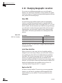
2.12 Changing Geographic Location . . . . . . . . . . . . . . . . . . . .58
3 Using the ADCU Interface . . . . . . . . . . . . . . . . . . . . . . .59
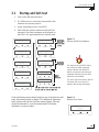
3.1 Startup and Self-test . . . . . . . . . . . . . . . . . . . . . . . . . . . .61
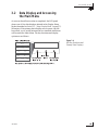
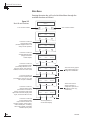
3.2 Data Display and Accessing the Main Menu . . . . . . . . . .63
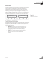
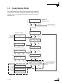
3.3 Setup Display Mode . . . . . . . . . . . . . . . . . . . . . . . . . . . .67
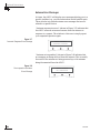
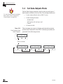
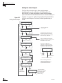
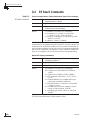
3.4 Set Data Outputs Mode . . . . . . . . . . . . . . . . . . . . . . . . . .68
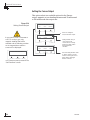
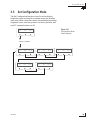
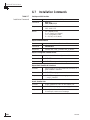
3.5 Set Configuration Mode . . . . . . . . . . . . . . . . . . . . . . . . . .73
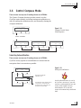
3.6 Control Compass Mode . . . . . . . . . . . . . . . . . . . . . . . . . .77
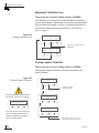
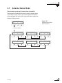
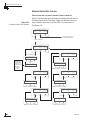
3.7 Antenna Status Mode . . . . . . . . . . . . . . . . . . . . . . . . . . .79
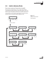
3.8 Control Antenna Mode . . . . . . . . . . . . . . . . . . . . . . . . . .81

54-0161
ii
TracVision G6 Technical Manual
4Troubleshooting . . . . . . . . . . . . . . . . . . . . . . . . . . . . .91
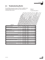
4.1 Troubleshooting Matrix . . . . . . . . . . . . . . . . . . . . . . . . . .93
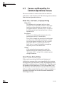
4.2 Causes and Remedies for Common
Operational Issues . . . . . . . . . . . . . . . . . . . . . . . . . . . . .94
4.3 GyroTrac-specific Issues . . . . . . . . . . . . . . . . . . . . . . . . .97
4.4 IRD Troubleshooting . . . . . . . . . . . . . . . . . . . . . . . . . . . .98
4.5 Antenna Gyro and LNB Faults . . . . . . . . . . . . . . . . . . . . .98
4.6 Computer Diagnostics . . . . . . . . . . . . . . . . . . . . . . . . . . .98
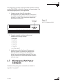
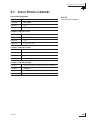
4.7 Maintenance Port Parser Commands . . . . . . . . . . . . . . .99
5 Maintenance . . . . . . . . . . . . . . . . . . . . . . . . . . . . . .101
5.1 Warranty/Service Information . . . . . . . . . . . . . . . . . . . . .103
5.2 Preventive Maintenance . . . . . . . . . . . . . . . . . . . . . . . .103
5.3 TracVision G6 Field Replaceable Units . . . . . . . . . . . . .104
5.4 PCB Removal and Replacement . . . . . . . . . . . . . . . . . .106
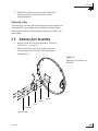
5.5 Antenna Gyro Assembly . . . . . . . . . . . . . . . . . . . . . . . .109
5.6 Azimuth Limit Switch Assembly . . . . . . . . . . . . . . . . . . .112
5.7 Elevation Motor and Belt Replacement . . . . . . . . . . . . .114
5.8 Antenna LNB Replacement . . . . . . . . . . . . . . . . . . . . . .116
5.9 GyroTrac Replaceable Parts . . . . . . . . . . . . . . . . . . . . .118
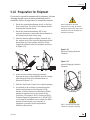
5.10 Preparation for Shipment . . . . . . . . . . . . . . . . . . . . . . . .119
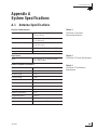
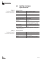
Appendix A System Specifications
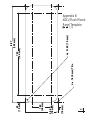
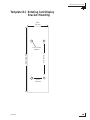
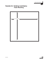
Appendix B ADCU Flush Mount Panel Template
Appendix C Comprehensive TracVision G6 System
Wiring Diagram
Appendix D Optional Rotating Card Display
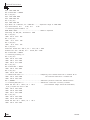
Appendix E Startup Data Sequences
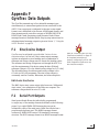
Appendix F Data Outputs
Appendix G Maintenance Port Parser Commands

Introduction
54-0161
1
1 – Introduction
This section provides a basic overview of the TracVision G6 system. It
explains how the TracVision system works and describes the function of
each component.
Contents
1.1 TracVision G6 System Overview . . . . . . . . . . . . . . . . . . . . . . . . . .3
1.2 TracVision G6 Components . . . . . . . . . . . . . . . . . . . . . . . . . . . . .5
1.3 Materials Provided With the TracVision G6 . . . . . . . . . . . . . . . . . .6


Introduction
54-0161
3
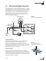
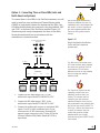
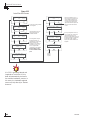
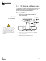
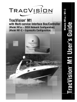
1.1 TracVision G6 System Overview
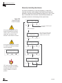
A complete satellite TV system, illustrated in Figure 1-1, includes
the TracVision G6 antenna unit connected to the GyroTrac digital
gyro-stabilized sensor, Advanced Digital Control Unit (ADCU),
an IRD (satellite TV receiver) and a television set. A desktop or
laptop computer is used to configure the system for satellite
selection and conduct diagnostics. System specifications are
provided in Appendix A on page 123.
System Compatibility
The TracVision G6 satellite antenna is fully compatible with
Digital Video Broadcasting (DVB
®
) satellites, as well as
DIRECTV
®
‘s Digital Satellite Service (DSS) satellites. The
system is also fully compatible with KVH’s TracNet
™
2.0 Mobile
High-speed Internet System (for more information about TracNet 2.0,
please visit our web site at www.kvh.com).
In-motion Tracking
The TracVision G6 uses a state-of-the-art actively stabilized
antenna system. Once the satellite is acquired, the antenna gyro
continuously measures the heading, pitch, and roll of your vessel
and sends commands to the antenna motors to keep the antenna
pointed at the satellite at all times.
Satellite Receiver 2
Satellite Receiver 1
Options Purchased Separately
GyroTrac Sensor
Advanced Digital
Control Unit (ADCU)
TracVision G6 Antenna
Interfaces to:
Autopilots
Radars
Plotters
Remote Displays
PC Diagnostics
GPS or
Ship's Gyro
11-16 VDC
3.5 - 4.5 Amps
Power
RF
TV 1
TV 2
RF
Data
Figure 1-1
TracVision G6 System Diagram
TracVision
Figure 1-2
TracVision Identifies and
Compensates for Vessel Motion

54-0161
4
TracVision G6 Technical Manual
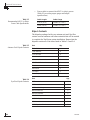
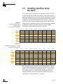
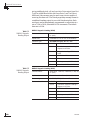
Satellite Library
Your TracVision G6 includes a pre-programmed satellite library
of European, North American, and Latin American satellite
services. When configuring the TracVision G6, you may choose a
pair of satellites from the library to be active in the system and
with your IRD. For the antenna to track and receive signals from
two satellites, they must be within 10º longitude of each other in
orbit. As a result, certain satellites can be paired only with certain
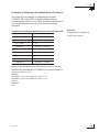
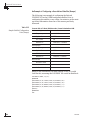
other satellites. Tables 1-1 and 1-2 list the possible satellite pairs
that may be selected in North America and Europe. In Latin
America, the system can track either Galaxy8W or Galaxy8E to
receive DIRECTV Latin America service (Latin American LNB
required). If the satellite service you wish to receive is not already in
the “satellite library,” you may also add two additional satellites of
your choice to the library.
TracVision G6’s default satellite
pairs are:
N. America (US DIRECTV):
DSS_101 & DSS_119
Europe: Astra 1 & Hotbird WB
L. America (DIRECTV LA):
Galaxy 8W & None
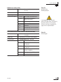
Table 1-2
Available Satellite Pairs - Europe
(European LNB required)
DSS_101 ✓✓✓
DSS_119 ✓✓✓
Echo_61 ✓✓ ✓✓
Echo_110 ✓ ✓✓✓✓
Echo_119 ✓✓ ✓✓✓
Echo_148 ✓✓ ✓✓
Expressvu ✓ ✓✓✓✓✓ ✓
ExpressTV ✓ ✓✓✓✓✓✓
DSS_101 DSS_119 Echo_61 Echo_110 Echo_119 Echo_148 Expressvu ExpressTV
Astra 1 ✓✓ ✓✓ ✓
Astra 2N ✓✓✓
Astra 2S ✓✓✓
Hispasat
Hotbird WB ✓✓✓ ✓
Sirius ✓✓✓
Thor ✓✓
Arabsat ✓✓✓ ✓
Nilesat ✓✓
Astra 1 Astra 2N Astra 2S Hispasat Hotbird WB Sirius Thor Arabsat Nilesat
Table 1-1
Available Satellite Pairs
- North America
(U.S.-style LNB required)

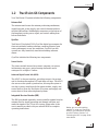
1.2 TracVision G6 Components
Your TracVision G6 system includes the following components:
Antenna Unit
The antenna unit houses the antenna positioning mechanism,
signal front end, power supply, and control elements within a
molded ABS radome. Weathertight connectors on the bottom of
the baseplate join the power, signal, and control cabling from
below-decks units.
GyroTrac
TracVision G6 includes KVH’s GyroTrac digital gyrocompass for
three-axis attitude/heading reference, ensuring superior open
water performance in any sea conditions. GyroTrac can also
operate as a fully functional, stand-alone heading reference
sensor.
GyroTrac includes the following two components:
Sensor Module
The sensor module houses the system’s compass/yaw sensor,
inclinometer, rate gyros, and processing electronics and is
waterproof to a depth of 1 meter.
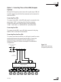
Advanced Digital Control Unit (ADCU)
The ADCU is the user interface, providing access to the system
and its functions through an LCD and three soft keys. The ADCU
also serves as the system’s junction box, allowing the system to
use ship’s power, interface with the sensor module, supply and
receive data to/from the TracVision G6 system, and supply and
receive data to/from other shipboard systems.
Integrated Receiver Decoder (IRD)
The IRD (purchased separately) receives satellite signals from the
antenna unit for signal processing and channel selection, and
sends the signals to the TV set for viewing. Please refer to the
user’s manual provided with your selected IRD for complete
operating instructions.
Introduction
54-0161
5
Before you can start watching
satellite TV using your TracVision
antenna, you will need to activate
your IRD. Refer to Section 2.8,
“Activating the IRD” on page 44 for
more details.

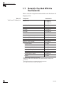
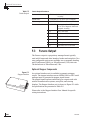
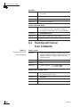
1.3 Materials Provided With the
TracVision G6
Table 1-3 lists the components and materials in the TracVision G6
shipping carton.
Component KVH Part No.
Antenna Unit 02-1045-01
†
02-1045-03
††
02-1045-04
†††
Installation Kitpack 72-0103
Data Cable 32-0619-100
PC Cable 32-0628-06
RF Cable* 32-0566-100
Power Cable 32-0510-100
Ground Cable 32-0583-50
TracVision G6 Technical Manual 54-0161
TracVision G6 User’s Guide 54-0161-01
GyroTrac, which includes: 01-0226-01
Sensor Module 02-1154
ADCU 02-0961
Flush Mount ADCU Panel 20-0667
Horizontal Sensor Bracket 20-0658
Vertical Sensor Bracket 20-0666
Sensor to ADCU Cable 32-0623-30
Kitpack 72-0095
†
North American TracVision G6 system
††
DIRECTV Latin America TracVision G6 system (formerly “Galaxy Latin
America”)
†††
European TracVision G6 system with quad-output LNB
* Not supplied with quad-output LNB systems.
54-0161
6
TracVision G6 Technical Manual
Table 1-3
TracVision G6 Packing List

Installation
54-0161
7
2 – Installation
This section explains how to install, configure, and test the
TracVision G6 system. Follow the simple procedures in this section
sequentially to ensure a safe and effective installation.
Contents
2.1 Planning the Installation . . . . . . . . . . . . . . . . . . . . . . . . . . . . . . . .9
2.2 Mounting the TracVision Antenna . . . . . . . . . . . . . . . . . . . . . . . .15
2.3 Mounting the GyroTrac Sensor . . . . . . . . . . . . . . . . . . . . . . . . . .19
2.4 Mounting the ADCU . . . . . . . . . . . . . . . . . . . . . . . . . . . . . . . . . .24
2.5 Connecting the Antenna RF Cable(s) . . . . . . . . . . . . . . . . . . . . . .26
2.6 Wiring the ADCU . . . . . . . . . . . . . . . . . . . . . . . . . . . . . . . . . . . .30
2.7 Calibrating the Sensor . . . . . . . . . . . . . . . . . . . . . . . . . . . . . . . .42
2.8 Activating/Programming the IRD . . . . . . . . . . . . . . . . . . . . . . . .44
2.9 Installing Satellites Using the ADCU . . . . . . . . . . . . . . . . . . . . . .46
2.10 Setting the Skew Angle
(European Systems Only) . . . . . . . . . . . . . . . . . . . . . . . . . . . . . .55
2.11 Checking Out the System . . . . . . . . . . . . . . . . . . . . . . . . . . . . . .56
2.12 Changing Geographic Location . . . . . . . . . . . . . . . . . . . . . . . . . .58


Installation
54-0161
9
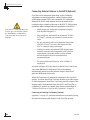
2.1 Planning the Installation
Who Should Install the TracVision G6
KVH recommends that a KVH-authorized technician install the
TracVision G6 system. Installers should have experience
installing electronic equipment on a vessel.
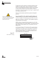
Materials and Equipment Required for Installation
Before you begin installing the TracVision G6 system, you need to
verify that you have all of the following tools and materials:
• Electric drill
• 1⁄2" (13 mm) drill bit and 3" (80 mm) hole saw
• Socket wrenches
• Flat head and Phillips screwdrivers
• Crimp tool (LRC #L3011B or equivalent)
• Light hammer; center punch; tape; scriber/pencil
•Terminal lug crimping tool; wire strippers
• A PC with terminal emulation software such as
PROCOMM or Windows Terminal or
Hyperterminal
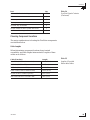
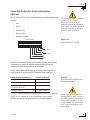
• RG-11 (75 ohms) cable for extra RF signal cables
as needed. Refer to Table 2-1 to determine the number
of RF cables that you will need.
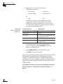
Connecting to: # RF Cables
North American Systems
One IRD 1
Two or more IRDs 2
European Systems
One IRD 1
Two IRDs 2
Three IRDs 3
Four IRDs 4
More than four IRDs *
* Follow multiswitch manufacturer’s guidelines
Plan the entire installation before
proceeding! Take into account
antenna unit placement, cable
running distances between units,
and accessibility to the equipment
after installation.
Table 2-1
Number of RF Cables Required

• Power cable to connect the ADCU to ship’s power
(Table 2-2 provides proper gauge and length
specifications)
Cable Length Cable Gauge
to 50 ft (15 m) 14 AWG (1.5 mm
2
)
+50 ft (+15 m) 12 AWG (2.5 mm
2
)
Kitpack Contents
The kitpacks packaged with your antenna unit and GyroTrac
contain various hardware and other materials that will be needed
to complete the TracVision system installation. Ensure that the
kitpacks contain all of the items listed in Tables 2-3 and 2-4.
Part Qty.
3
⁄8-16 x 3" hex screws 4
3
⁄
8 flat washers 8
3
⁄8-16 hex nuts 4
3
⁄8 lock washers 4
3
⁄
8 fiber shoulder washer 8
#10-32 x
5
⁄
8" flat head screws 6
Plastic screw covers 12
Foam seal 1
Tie-wraps 2
Core clamp 1
Part Qty.
#8 fiber washers 10
#8 flat washers 10
#8-32 self-locking nuts 5
#10 flat washers 5
#10 lock washers 5
#10-32 Phillips head screws 5
#8-32 Phillips head screws 5
#8 lock washers 5
#8 Phillips head black screws 5
54-0161
10
TracVision G6 Technical Manual
Table 2-3
Antenna Unit Kitpack Contents
Table 2-4
GyroTrac Kitpack Contents
Table 2-2
Recommended ADCU-to-Ship’s
Power Cable Specifications

Part Qty.
Velcro self-adhesive backings 8
Velcro washers 4
4" tie-wraps 5
Tie-wrap screw mount 6
Terminal strip connectors 5
Sensor module to ADCU power wire ferrite 1
#4-24 thread-forming screws 4
Choosing Component Locations
The major considerations in locating the TracVision components
are described below.
Cable Lengths
When determining component locations, keep in mind
accessibility and cable lengths between units. Lengths of these
cables are as follows:
Cable (Function) Length
Data Cable (ADCU to Antenna Unit) 100 ft (30 m)
PC Cable (ADCU to PC) 6 ft (2 m)
RF Cable (Antenna to IRD) 100 ft (30 m)
Power Cable (Power to Antenna Unit) 100 ft (30 m)
Sensor to ADCU Cable (GyroTrac) 30 ft (10 m)
IRD Ground to ADCU Ground Cable 50 ft (15 m)
Installation
54-0161
11
Table 2-5
Lengths of Provided
Below-decks Cables
Table 2-4
GyroTrac Kitpack Contents
(Continued)

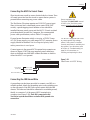
Choosing the Best Location for the TracVision Antenna
There are several factors to consider when choosing the location
for the TracVision antenna.
• Since the TracVision antenna requires a clear view
of the southern sky to receive satellite signals, the
ideal antenna site has an unobstructed view of the
horizon/satellite all around.
• Keep the antenna clear of any obstructions above
decks. The antenna requires a 10º to 80º look angle
to receive satellite signals.
• To minimize tracking errors, place the antenna
unit as close as possible to the intersection of the
vessel’s fore-and-aft centerline and midships. The
antenna unit need not be located exactly on the
vessel’s fore-and-aft axis, but its centerline MUST
be parallel to it.
• The mounting surface should be flat and strong
enough to carry the complete assembly (55 lbs/
25 kg). Make sure that the mounting surface is
rigid so that it cannot flex when the vessel
vibrates. If necessary, add a strength member to
the mounting site to stiffen it.
• Be sure to account for the height and base
dimensions (see Figure 2-2).
54-0161
12
TracVision G6 Technical Manual
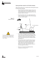
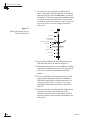
The antenna unit should not be too
high off the water (a height above
the waterline no more than half the
vessel length).
Blocked!
TracVision Antenna
Vessel Platform
Mast
Figure 2-1
Antenna Blockage

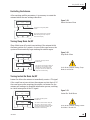
Radar Concerns
The TracVision antenna must be kept out of line with nearby
radars, as their energy levels may overload the antenna’s front-
end circuits. In an ideal installation, the antenna is mounted four
feet above and four feet away from the radar (measured from the
center of the antenna dome to the center of the radar). The best
placement for the TracVision antenna is above the radar.
However, if there will be a significant horizontal separation
between the radar and TV dome (i.e., at least 8 to 10 feet), the
TracVision antenna can be placed below the radar as there will be
little chance of signal blockage.
Installation
54-0161
13
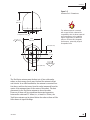
FWD
27.36"
(695 mm)
Compression Seal
4x .50"
(4x 13 mm)
26.2"
(665 mm)
12.0"
(305 mm)
6.0" (152 mm)
6.0" (152 mm)
12.0"
(305 mm)
Figure 2-2
Antenna Unit Dimensions
The radome exterior is treated
with a special finish selected for
compatibility with the dome material
and transparency to the satellite
signals. Application of additional
paints or finishes WILL degrade
performance, potentially beyond
acceptable limits.

Choosing the Best Location for the GyroTrac Sensor Module
• Ideally, the sensor module should be mounted as
low as possible in the center of the vessel – but
NOT in the bilges.
• The mounting surface should be free of excessive
vibration and flexing.
• Maintain at least four feet (1.3 m) separation
between the sensor module and any magnetized
materials, large ferrous masses, cranes, derricks,
other antennas, cables carrying high amperage
direct current, or battery banks. Take extra care
when mounting the sensor on a steel vessel; use an
aluminum, brass, plastic, or wood (NOT steel or
iron) platform to position the antenna at least four
feet (1.2 m) from the steel surface.
•
Be alert for devices that change their magnetic
characteristics when in use, such as CRTs
(computer and TV screens), radar magnetrons,
electric winches, loudspeakers, windshield wipers,
and other devices with DC motors. GyroTrac
cannot compensate for changing magnetic fields
created by these devices.
• If you need to fabricate custom mounting brackets
for the sensor module, they should be made from
non-ferrous materials such as wood, brass,
aluminum, fiberglass, or plastic.
Choosing the Best Location for the ADCU
• The ADCU should be mounted in a dry location,
allowing enough room at the back for connecting
system cables.
• The ADCU should be placed so that the LCD
display is visible and the buttons are accessible.
• The ADCU is not susceptible to magnetic
interference and does not need to be mounted on a
level surface.
54-0161
14
TracVision G6 Technical Manual
If uncertain of the best location
for the sensor module, make a
temporary installation and conduct
a compass calibration (as
described in Section 2.7,
“Calibrating the Sensor Module”on
page 42). Any necessary
adjustments to the sensor location
can be made based on the
calibration scores.

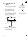
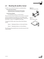
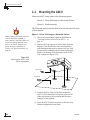
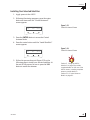
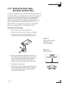
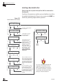
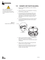
2.2 Mounting the TracVision
Antenna
1. Make sure that you have chosen a suitable
mounting location based upon the guidelines in
“Choosing the Best Location for the TracVision
Antenna” on page 12.
2. Remove the antenna unit from its shipping carton
and set the radome aside in a safe place.
3. Remove the foam shipping restraints from the
antenna unit.
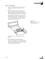
4. Using the template provided at the back of this
manual or the dimensions shown in Figure 2-3, lay
out the four mounting bolt holes and cable access
hole at the mounting site. Make certain that the
Forward arrow is parallel with the vessel’s
centerline and pointed toward the bow.
5. Drill the four
1
⁄2" (13 mm) bolt holes and cut out the
3" (80 mm) diameter cable access hole (following
the layout in Step 4). Smooth the edges of the cable
access hole to protect the cables.
Installation
54-0161
15
The foam shipping restraints must
be removed before power is
applied. Save the foam pieces for
reuse.
Be careful not to strike the exposed
connectors extending from the
bottom of the baseplate or allow
them to carry the weight of the
antenna unit.
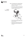
Figure 2-3
Antenna Mounting Holes Layout
FWD
DOME
26.2"
( 67 cm)
4 x 0.5"
(4 x 1.3 cm)
3"
( 7.6 cm)
12"
(30.5 cm)
6"
(15.2 cm)
12"
(30.5 cm)
6"
(15.2 cm)

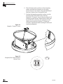
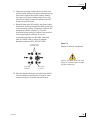
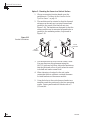
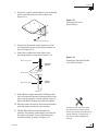
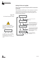
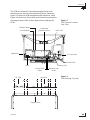
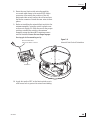
6. Place the foam seal in position on the mounting
surface with the hole centered over the cable
access cutout. Do not remove the paper backing at
this time. Scribe a line all around the seal.
7. Position the baseplate assembly in place over the
mounting holes and cable access, with the
baseplate’s “Forward” arrow (shown in Figure 2-4)
pointing toward the bow. Ensure that all holes line
up and that the connectors are centered over the
cable access as shown in Figure 2-5. Make any
necessary adjustments before seating the foam seal
in place permanently.
54-0161
16
TracVision G6 Technical Manual
Figure 2-4
Baseplate “Forward” Arrow
FWD
Figure 2-5
Baseplate/Foam Seal Orientation
(Bottom View)
Page is loading ...
Page is loading ...
Page is loading ...
Page is loading ...
Page is loading ...
Page is loading ...
Page is loading ...
Page is loading ...
Page is loading ...
Page is loading ...
Page is loading ...
Page is loading ...
Page is loading ...
Page is loading ...
Page is loading ...
Page is loading ...
Page is loading ...
Page is loading ...
Page is loading ...
Page is loading ...
Page is loading ...
Page is loading ...
Page is loading ...
Page is loading ...
Page is loading ...
Page is loading ...
Page is loading ...
Page is loading ...
Page is loading ...
Page is loading ...
Page is loading ...
Page is loading ...
Page is loading ...
Page is loading ...
Page is loading ...
Page is loading ...
Page is loading ...
Page is loading ...
Page is loading ...
Page is loading ...
Page is loading ...
Page is loading ...
Page is loading ...
Page is loading ...
Page is loading ...
Page is loading ...
Page is loading ...
Page is loading ...
Page is loading ...
Page is loading ...
Page is loading ...
Page is loading ...
Page is loading ...
Page is loading ...
Page is loading ...
Page is loading ...
Page is loading ...
Page is loading ...
Page is loading ...
Page is loading ...
Page is loading ...
Page is loading ...
Page is loading ...
Page is loading ...
Page is loading ...
Page is loading ...
Page is loading ...
Page is loading ...
Page is loading ...
Page is loading ...
Page is loading ...
Page is loading ...
Page is loading ...
Page is loading ...
Page is loading ...
Page is loading ...
Page is loading ...
Page is loading ...
Page is loading ...
Page is loading ...
Page is loading ...
Page is loading ...
Page is loading ...
Page is loading ...
Page is loading ...
Page is loading ...
Page is loading ...
Page is loading ...
Page is loading ...
Page is loading ...
Page is loading ...
Page is loading ...
Page is loading ...
Page is loading ...
Page is loading ...
Page is loading ...
Page is loading ...
Page is loading ...
Page is loading ...
Page is loading ...
Page is loading ...
Page is loading ...
Page is loading ...
Page is loading ...
Page is loading ...
Page is loading ...
Page is loading ...
Page is loading ...
Page is loading ...
Page is loading ...
Page is loading ...
Page is loading ...
Page is loading ...
Page is loading ...
Page is loading ...
Page is loading ...
Page is loading ...
Page is loading ...
Page is loading ...
Page is loading ...
Page is loading ...
Page is loading ...
Page is loading ...
Page is loading ...
Page is loading ...
Page is loading ...
Page is loading ...
Page is loading ...
Page is loading ...
Page is loading ...
Page is loading ...
Page is loading ...
Page is loading ...
Page is loading ...
Page is loading ...
Page is loading ...
Page is loading ...
Page is loading ...
Page is loading ...
Page is loading ...
Page is loading ...
-
 1
1
-
 2
2
-
 3
3
-
 4
4
-
 5
5
-
 6
6
-
 7
7
-
 8
8
-
 9
9
-
 10
10
-
 11
11
-
 12
12
-
 13
13
-
 14
14
-
 15
15
-
 16
16
-
 17
17
-
 18
18
-
 19
19
-
 20
20
-
 21
21
-
 22
22
-
 23
23
-
 24
24
-
 25
25
-
 26
26
-
 27
27
-
 28
28
-
 29
29
-
 30
30
-
 31
31
-
 32
32
-
 33
33
-
 34
34
-
 35
35
-
 36
36
-
 37
37
-
 38
38
-
 39
39
-
 40
40
-
 41
41
-
 42
42
-
 43
43
-
 44
44
-
 45
45
-
 46
46
-
 47
47
-
 48
48
-
 49
49
-
 50
50
-
 51
51
-
 52
52
-
 53
53
-
 54
54
-
 55
55
-
 56
56
-
 57
57
-
 58
58
-
 59
59
-
 60
60
-
 61
61
-
 62
62
-
 63
63
-
 64
64
-
 65
65
-
 66
66
-
 67
67
-
 68
68
-
 69
69
-
 70
70
-
 71
71
-
 72
72
-
 73
73
-
 74
74
-
 75
75
-
 76
76
-
 77
77
-
 78
78
-
 79
79
-
 80
80
-
 81
81
-
 82
82
-
 83
83
-
 84
84
-
 85
85
-
 86
86
-
 87
87
-
 88
88
-
 89
89
-
 90
90
-
 91
91
-
 92
92
-
 93
93
-
 94
94
-
 95
95
-
 96
96
-
 97
97
-
 98
98
-
 99
99
-
 100
100
-
 101
101
-
 102
102
-
 103
103
-
 104
104
-
 105
105
-
 106
106
-
 107
107
-
 108
108
-
 109
109
-
 110
110
-
 111
111
-
 112
112
-
 113
113
-
 114
114
-
 115
115
-
 116
116
-
 117
117
-
 118
118
-
 119
119
-
 120
120
-
 121
121
-
 122
122
-
 123
123
-
 124
124
-
 125
125
-
 126
126
-
 127
127
-
 128
128
-
 129
129
-
 130
130
-
 131
131
-
 132
132
-
 133
133
-
 134
134
-
 135
135
-
 136
136
-
 137
137
-
 138
138
-
 139
139
-
 140
140
-
 141
141
-
 142
142
-
 143
143
-
 144
144
-
 145
145
-
 146
146
-
 147
147
-
 148
148
-
 149
149
-
 150
150
-
 151
151
-
 152
152
-
 153
153
-
 154
154
-
 155
155
-
 156
156
-
 157
157
-
 158
158
-
 159
159
-
 160
160
-
 161
161


KVH Industries KVH TracVision TracVision G6 Installation & Technical Manual
- Category
- Satellite antennas
- Type
- Installation & Technical Manual
Ask a question and I''ll find the answer in the document
Finding information in a document is now easier with AI
Related papers
-
KVH Industries KVH TracVision TracVision G6 Technical Manual
-
-
-
-
-
-
-
-
-
Other documents
-
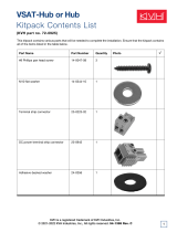 KVH VSAT HUB Contents List
-
 KVH TracNet H60 in 1 m (41.5") Dome Kitpack Contents List
-
 KVH TracNet H90 Contents List
-
 KVH TracNet H60 Contents List
-
 KVH TracNet H60 Contents List
-
Lennox iComfort Thermostat Mag-Mount (12X99) Installation guide
-
 TracVision TV6 Installation guide
-
 KVH TracNet H90 AgilePlans Contents List
-
 TracVision TV5 Installation guide
-
 TracVision M1DX User manual


