Page is loading ...

Instruction Sheet Number 1101FIC
Page 1 of 2 Installation Procedure for High Wattage Insulated Ceiling
Frame-In Kits 100IFIC, 1101FIC, 2001FIC
Lightolier a Genlyte company www.lightolier.com
631 Airport Road, Fall River, MA 02720 • (508) 679-8131 • Fax (508) 674-4710
We reserve the right to change details of design, materials and finish.
© 2007 Genlyte Group LLC • B0607
Read and understand these instructions before installing fixture.
This fixture is intended for installation in accordance with the National Electrical Code and local regulations. To assure full compliance with local codes and
regulations, check with your local electrical inspector before installation. To prevent electrical shock, turn off electricity at fuse box before proceeding.
Retain these instructions for maintenance reference.
Fig. A
Frame-In
Fig. B
Wire-In
Fig. C
Swing-Up
Fig. D
Close-In
Fig. E
Snap-On
Fig. F
Push-Up
New Construction
NOTE: I.C. Frame-In Kit may be used in direct contact with insulation.
Warning: Use Only With Lightolier Reflector Trims Marked With I.C. Lamping Information.
Use of Other Manufacturers’ Trims Voids the Underwriters Laboratories Listing and Could Constitute A Fire Hazard
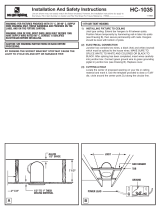
For Joist Spacing Less Than 16" On Center (To 12" On Center):
• MOUNTING BAR CHANNELS can be shortened and used as nailing
legs in tight spaces. Simply remove INNER BAR from holed CHANNEL,
bend CHANNEL at appropriate point and use extra screw to secure it
to the joist. (Fig. G)
5 3/4" 2001FR
5 1/4" 1004ICX
5 5/8" 1101FIC
5 7/8" 2001FIC
6 3/8" 1001FIC
6" 1101FIC
CENTER LINE OF
APERTURE OPENING
HINGED MOUNTING BAR
Note: Integral nail version available
Fig. G
TAB
T-BAR
HINGED BAR ENDS
CHANNEL
TAB
BEND AT TAB
BEND AT HOLE
1. FRAME-IN (Fig. A)
Locate fixture along joist and line up bottom edge of HINGED MOUNTING BAR
with the bottom of joist and fasten in place.
For suspended ceilings:
• Rotate HINGED BAR ENDS to position shown and fully extend bars.
• Crimp bottom of edge of CHANNEL to prevent rotation of
HINGED BAR ENDS.
• Bend NON-HINGED end of mounting bar at featured hole location and
extend out.
• Position notched area of MOUNTING BARS onto T-BAR and lock by
bending TAB underneath T-BAR BEAD as shown.
• For suspended ceiling, make certain that bottom of Mounting Frame is no
higher than 1" above ceiling line.

Lightolier a Genlyte company www.lightolier.com
631 Airport Road, Fall River, MA 02720 • (508) 679-8131 • Fax (508) 674-4710
We reserve the right to change details of design, materials and finish.
© 2007 Genlyte Group LLC • B0607
Instruction Sheet Number 1101FIC
Page 2 of 2 Installation Procedure for High Wattage Insulated Ceiling
Frame-In Kits 100IFIC, 1101FIC, 2001FIC
U.S. and Foreign Patents Pending
HINGED KNOCK OUT
J-BOX COVER
NON-METALLIC
SHEATHED CABLE
(12 OR 14 GAUGE ONLY)
CABLE CLAMP
JUNCTION BOX
DEFORM MATERIAL AT ANY
CORNER OF FRAME FOR ADDI-
TIONAL LOCK IF NEEDED
LOCKING SCREW
2. WIRE-IN (Fig. B)
Open hinged J-BOX COVER fully to its locked position (lift slightly to unlock).
Open hinged KNOCK OUT to allow NON-METALLIC CABLE to enter JUNCTION
BOX. Push CABLE through CLAMP.
Note: Wiring and connections must not be placed in JUNCTION BOX in a
manner which will interfere with the CLAMPS action to provide strain relief.
Wire to SUPPLY LEADS. WHITE FIXTURE LEAD to NEUTRAL SUPPLY LEAD.
BLACK FIXTURE LEAD to HOT (120V) SUPPLY LEAD. BARE FIXTURE WIRE to
SUPPLY GROUND. Use wirenuts (local hardware item). Place all electrical con-
nections in the J-BOX and close the J-BOX COVER.
3. SWING-UP (Fig. C)
Extend MOUNTING BAR to reach opposite joist and fasten in place.
Adjust to desired position along MOUNTING BAR and lock in place using
LOCKING SCREW.
4. CLOSE-IN (Fig. D)
Install plasterboard or other dry type ceiling. Hole in board can be cut either
on the floor or after the board is secured to the ceiling using MOUNTING
FRAME opening as cutting guide. Make sure spring clips are rotated out of
hole area to be cut, also making sure that socket and wiring are positioned
away from hole area. Spring clips can only be rotated counterclockwise. This
detail allows easy removal of reflector trim by rotating TRIM counterclock-
wise and permits installing Reflector Trim tightly against the ceiling surface
by rotating trim clockwise after pushing Trim into ceiling.
5. AIRSEAL
®
INSTALLATION (optional)
Install a bead of silicone caulking compound between the ceiling opening and
edge of HOUSING. Housings are tested in accordance with ASTM E 283 (max
2 cfm @ 75 pa) and comply with WSEC & IECC when installed as instructed.
6. SNAP-ON (Fig. E)
Important - Insert SOCKET CUP in
neck of REFLECTOR making sure
SPRING TABS fully engage into SLOTS
in REFLECTOR.
7. PUSH-UP (Fig. F)
Push REFLECTOR TRIM straight up
until it is tight against ceiling.
8. BALLAST REPLACEMENT
A qualified electrician must perform ballast replacement. Turn off power.
Remove reflector trim from luminaire. Remove fasteners that secure the bal-
last to the housing. Remove ballast assembly through ceiling hole. Disconnect
all input wiring to the ballast. Release all wires from ballast wire connectors
by inserting small blade tool with insulated handle into wire release slots
(Figure H). Remove ballast and replace with new ballast. Rewire, see label on
ballast for wiring diagram then reassemble.
See Separate
Reflector Trim
Instruction
Sheets
}
REMOVE
INSE
RT
BALLAST WIRE
CONNECTORS
WIRE RELEASE
BLADE
(BY OTHERS)
WIRE RELEASE
SLOTS
Figure H
/