
Originalinstructions
Usermanual
MX²30–95G
Desiccantdehumidifier
withgasheaterforreactivation
Appliestoallunitsmanufactured
fromweek01,2015.
190TEN–1090–G1412 ©MuntersEuropeAB2015

Importantuserinformation
Intendeduse
Munters dehumidifiers are intended to be used for the
dehumidificationofair.Anyotheruseoftheunit,or
use which is contrary to the instructions given in this
manual, can cause personal injury and damage to the unit
and other proper ty.
No modification of the unit is allowed without prior
approvalby Munters. Attachment or installation
of additional devic es is only allowed after written
agreement by Munters.
Warranty
Thewarrantyp
eriodisvalidfromthedatetheunit
left our f acto
ry, unless otherw ise stated in writing.
Thewarranty
is limited to a free exchange of parts or
components w
hich have failed as a result of defects in
materials o
rworkmanship.
All war ranty claims must include proof that the
fault has occurred within the warranty period an d
that the u n it has been used in accordance with the
specifications. All claims must specify the unit type and
fabrication number. This infor mation is stamped on the
identification plate, see section Marking.
It is a condition of the war ranty that the unit for the full
warranty period is serviced and maintained by a qualified
Munters engineer or Munter s approved engineer.
Access to specific and calibrated test equipmen t is
necessary. The service and maintenance must be
documented for the warranty to be valid.
Alway s contact Munters for ser vic e or repair. Operating
faults can o ccur if the unit is maintained insufficiently or
incorrectly.
Safety
Information about dangers are in this manual indicated
by the common hazard symbol:
WARNING!
Indicatesapossibledangerthatcanleadtopersonalinjury.
CAUTIO N!
Indicatesapossibledangerthatcanleadtodamagetothe
unitorotherproperty,orc auseenvironmentaldamage.
NOTE!
Highlightssupplementaryinformationforoptimal
useoftheunit.
ConformitywithDirectives
The dehumidifier is in conformity with the essential
safety requirements of the Machinery Directive
2006/42/EC, and in conformity with the provisions
of the Ecodesign Directive (ErP) 2009/125/EC, the
Ecodesign Directive for electric motors 2005/32/EC
and of the EMC Directive 2014/30/EU. The
dehumidifier is manufactured by an organization
certified according to ISO 9001 and ISO 14001.
Copyright
The contents of this manual can be changed without
prior notice.
NOTE!
Thismanualcontainsinformationwhichis
protectedbycopyrightlaws. Itisnotallowedtoreproduceor
transmitanypartofthismanualwithoutwrittenconsentfrom
Munters.
Please send any co mments regarding this manual to:
Munters Euro pe AB
Technical Documentation
P.O. Box 1150
SE- 164 26 KISTA Sweden
e-mail: t-doc@munters.se
ii
Importantuserinformation
190TE N–1090–G141 2

Tableofcontents
Importantuserinformation ............... ii
Intendeduse ...........................
ii
Warranty ...............................
ii
Safety ..................................
ii
ConformitywithDirectives ............
ii
Copyright ..............................
ii
Tableofcontents ........................... iii
1 Introduction ................................. 1
1.1 General ................................
1
1.2 Aboutthismanual .....................
1
1.3 Safetyandcautions ...................
1
1.3.1 Safetylabels ...................
2
1.4 Operationmonitoring .................
2
1.5 Applicationlimitations .................
3
1.6 Faultindications .......................
3
1.7 Marking ................................
4
1.7.1 Identificationplate .............
4
1.7.2 Gasburnerdata ................
4
1.7.3 Pressuretestpoints ...........
5
2 Dehumidifierdesign ....................... 6
2.1 Productdescription ...................
6
2.2 Principleofoperation ..................
6
2.3 Maincomponents,MX²30 ............
8
2.4 Maincomponents,MX²35–95 .......
10
2.5 Gasburnerunit ........................
12
2.6 GasMultiBloc
®
controlunit ............
13
2.6.1 Principleofoperation ..........
13
2.6.2 Overview .......................
14
2.6.3 Lowpressureswitch ...........
14
2.7 Gascontrolvalveunit .................
15
2.8 Burnersafetycontrolunit .............
16
2.8.1 Operation–start-up
sequence .......................
16
2.8.2 Programmeindicator ..........
17
2.8.3 Flamedetection ................
18
2.8.4 Shutdown/Lockout ............
18
2.9 Hightemperaturecut-out .............
19
2.10 Configurationfeatures ................
20
2.10.1Insulatedprocessairinlet .....
20
2.10.2Processfancontrol ............
20
2.10.3Bypassdamper ................
21
2.10.4EnergyRecoveryPurgeand
EnergyEfficiencyPurge .......
22
2.10.5LowDewpointPurge ..........
23
3 Installation ................................... 24
3.1 Safety ..................................
24
3.2 Movingthedehumidifier ..............
24
3.3 Inspectionofdelivery ..................
24
3.4 Storingthedehumidifier ..............
25
3.5 Siterequirements .....................
25
3.6 Foundation ............................
26
3.7 Ductinstallation .......................
27
3.7.1 Generalrecommendations ...
27
3.7.2 Ductforoutdoorairinlet .......
28
3.7.3 Ductforwetairoutlet ...........
28
3.7.4 Ductconnectiondimensions,
airinlets ........................ 29
3.7.6 Ductconnectiondimensions
(unitwithoutprocessfan) ......
30
3.7.7 Ductconnectiondimensions,
processfan ....................
31
3.7.8 Ductconnectiondimensions,
reactivationfan ................ 32
3.8 Gasandairsupply .....................
33
3.9 Electricalconnections ................
34
3.10 Externalhumiditytransmitter .........
34
4 Commissioning ............................. 35
4.1 Pre-startchecks .......................
35
4.2 Adjustmentofgasburner .............
35
4.3 Airflowadjustment ....................
37
4.3.1 General .........................
37
4.3.2 Settingtheratedairflows ......
38
4.3.3 Baseconfigurationsettings ...
39
4.4 Settingandtestingthegasburner ....
39
4.4.1 Settingmaximumeffect .......
39
4.4.2 Settingminimumeffect ........
41
5 Operation .................................... 42
5.1 Controlpanel ..........................
42
5.2 General ................................
43
5.3 Quickstop ..............................
43
190TEN–1090–G1412
Tableofcontents
iii

5.4 Operatingtheunit .....................
44
5.4.1 Initialstart-up,Manualmode
(MAN) ...........................
44
5.4.2 Initialstart-up,Automaticmode
(AUTO)–regulatingtoset
point ............................
44
6 Serviceandmaintenance ................. 45
6.1 Safety ..................................
45
6.2 Regularserviceandmaintenance ...
45
6.3 Serviceoptions ........................
46
6.4 Extendedwarranty ....................
46
6.5 Serviceindicatorlamp ................
46
6.6 Serviceandmaintenanceschedule
(0–24000hours) .......................
47
6.7 Serviceandmaintenanceschedule
(28000–48000hours) .................
48
6.8 Maintenanceofgasheaterunit .......
48
6.8.1 Maintenanceschedule ........
49
6.9 Airfilterreplacement ..................
50
7 Faulttracing ................................. 52
7.1 Safety ..................................
52
7.2 Faulttracinglist,dehumidifier ........
53
7.3 Faulttracinglist,gasheaterunit ......
55
7.3.1 Measuringflamesignaland
differentialgaspressure .......
57
8 Technicalspecification .................... 58
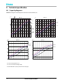
8.1 Capacitydiagrams ....................
58
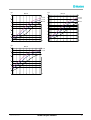
8.2 Noisedata .............................
60
8.2.1 Noisetoroom ..................
60
8.2.2 Noiseinducts .................. 62
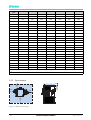
8.3 Dimensionsandservicespace ......
64
8.3.1 Dimensions ....................
64
8.3.2 Dimensions(unitwithout
processfan) ....................
65
8.3.3 Servicespace ..................
66
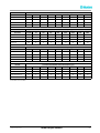
8.4 Technicaldata .........................
67
9 Scrapping .................................... 70
10 ContactMunters ............................ 71
iv
Tableofcontents
190TE N–1090–G141 2

1 Introduction
1.1 General
Munters manufactures a w ide range of e fficient dehumidifiers designed for different uses and applications.
Contact your nearest Munters office if you have any questions reg a rding the installat ion or the use of your
dehumidifier.
For product data, see section Technical specification.
Reactivation using a gas heater means that natural g as or propane/LPG (option) is the source of energy
that is use d to reactivate the dehum idifier's rotor. This technique is intended for use where nat ural gas or
propane/LPG is available as a n alternative to heating with electricity or steam.
1.2 Aboutthismanual
This manual contains necessary information for how to install and use the dehumidifier in a safe and
efficient way. Operation instructions for the control system can be f ound in a separate supplement, also
delivered with t he dehumidifier.
NOTE!
Makesuretoreadallrelevantpartsofthismanualbeforeoperatingorperforminganyworkonthe
dehumidifier. Thismanualshouldbestoredinapermanentlocationclosetothedehumidifier.
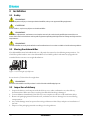
1.3 Safetyandcautions
Every measure has been taken in the design and manufacture of the dehumidifier to ensure that it meets the
safety requirements of the directives and standar ds listed in the EC Declaration of Conform ity.
The information in this manual shall in no way take precedence over individual responsibilities or local
regulations.
During operation and other work with a machine it is always the responsibility of the individual to consider:
■
The safety of all persons concerned.
■
The safety of the unit and other proper ty.
■
The protection of the environment.
The types of dangers that are indicated in this manual are described in section Important user information.
190TEN–109 0–G1412
Introduction
1

WARNING!
-Theunitmustnotbesplashedwithorimmersedinwater.
-Theunitmustneverbeconnectedtoavoltageorfrequencyotherthanthatforwhichitwasdesigned. Refertothe
identificationplate. Linevoltagethatistoohighcancauseanelectricalshockhazardanddamagetotheunit.
-Donotinsertfingersoranyotherobjectsintotheairvents.
-Allelectricalinstallationsmustbecarriedoutbyaqualifiedelectricianandinaccordancewithlocalregulations.
-Thedehumidifiercanrestartautomaticallyafterapowercut. Alwayssetandlockthemainpowerswitchinthe
OFFpositionbeforecarryingoutanyservicework.
-Useonlyapprovedliftin
gequipmenttopreventpersonalinjuryanddamagetotheequipment.
-AlwayscontactMuntersforserviceorrepair.
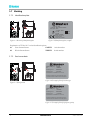
1.3.1 Safetylabels
The safety labels below are attached to the unit. Make sure that all personnel working with or near the unit
are aware of the meaning of each label.
Figure 1.1 Risk of p ersonal inju ry due to electric shock. Figure 1.2 R isk of personal injury due to hot surfaces.
1.4 Operationmonitoring
Thedehumidifier is controlled and monitored from the control panel on the front of the unit, see section
5.1, Control panel. The HMI (Human M achine Interface) is used to display values and parameters, and t o
input settings and commands to the control system. The HMI is described in the separate supplem ent.
2
Introduction
190TEN–1090–G1412

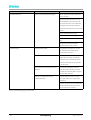
1.5 Applicationlimitations
Thedehumidifier conforms to the emission limits of residential, commercial and light-industrial
environments except for the emission limits for harmonics emission (EN 61000-3-12).
As the equipment exceeds the limits for harmonics it must not be used in residential, commercial or
light-industrial environment without taking proper steps regarding the power installation like supplying the
equipment from a dedicated transformer connected to t he high or medium voltage network.
Thedehumidifier conforms to R
sce
33, see Table 1.1.
Harmonic, number Limit (%)
1)
Measured value (%)
18
0,32
3 4 0,24
4 10,7 4,00
5 2,67 0,05
6
7,2
2,09
7
2
0,05
9 1,6 0,02
10 3,1 0,56
11
1,33 0,01
12 2
0,54
PWHD
2)
22
3,1
1)
Measured values valid for R
sce
=33
2)
Partial Weighted Harmonic Distortion
Table 1.1
Thedehumi
difier must only be used in industrial environments (class A) when the HMI is equipped w ith a
touch pa n
el. If the HMI is equipped with a text panel, the dehumidifier can be used in all environments
since t he
text panel is approved according to class B.
Thedehumidifier is intended for indoor installation only.
1.6 Faultindications
Any faults are indicated by the red light on the control panel. The cause of the alarm is indicated on the
display.
190TEN–109 0–G1412
Introduction
3

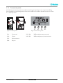
1.7 Marking
1.7.1 Identificationplate
MX² 35-95G
MX² 30G
Figur e 1.3 Position of id
entification plate
1005 170XXX XXXXX
4,1 kW
Max
4,6 kW
Munters Europe AB
Isafjordsgatan 1
164 26 Kista, Sweden
M
GAS
Made in Sweden
Fabr. No.
Fabr. year 2010
3 ~ 400V 50 Hz
Type
IP33
MX² 55G
Figure 1.4 Identificatio
n plate, example
Explanation of "Fabr. N
o" on the identification plat e:
10 Year of manufacture 170XXX Article number
05 Week of manufacture XXXXX Serial number
1.7.2 Gasburnerdata
AT-BE-DK-DE-ES-FI-FR-GB-GR-IE-IT-LU-NL-PT-SE
Qn:
Inlet pressure:
150 kW net.
B22-C12-C32
G20-G25
18-30 mbar
This unit must be installed in accordance with the rules in force.
Consult instructions before installation and use of this appliance.
Unit Gas Category:
Unit Categories:
Figure 1.6 Example of label for natural gas
MX² 30G
MX² 35-95G
Figure 1.5 Label position
AT-BE-DK-DE-ES-FI-FR-GB-GR-IE-IT-LU-NL-PT-SE
Qn:
Inlet pressure:
150 kW net.
B22-C12-C32
G31
18-30 mbar
This unit must be installed in accordance with the rules in force.
Consult instructions before installation and use of this appliance.
Unit Gas Category:
Unit Categories:
Figure 1 . 7 Example of label for pr opane (option)
4
Introduction
190TEN–1090–G1412

1.7.3 Pressuretestpoints
The built-in pressure t est points are used for measuring pressure drop across components during
basic installation work and inspection of the rotor condition. For airflow adjustment, refer to section
4.3, Airflow adjustment .
MX² 30G
MX² 35-95G
Figure 1.8 Label positi
on
TP1
TP2
TP3
TP4
Figure 1.9 Pressure tes
tpoints
TP1. Process air TP1–TP4. Differentialpressur
e, process air
TP2. Wet air TP2–TP3. Differential pressu
re, reactivation a ir
TP3. Reactivation air
TP4. Dr y air
190TEN–109 0–G1412
Introduction
5

2 Dehumidifierdesign
2.1 Productdescription
The desiccant dehumidifier has been designed to effectively dehumidify the air in environments requiring
low air humidity.
All functional components are enclosed in a corrosion resistant Aluzink
®
casing (standard) or stainless steel
casing (option) which makes installation and maintenance easy. The unit is constructed on a steel base frame
which allows the use of a fork-lift truck during transportation and installation.
The electrical control system complies with standard EN 60204-1. The electrical components are mounted
on bus bars. The dehumidifier is manufactured according to E uropean standards and the established
requirements for CE-marking.
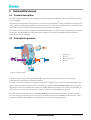
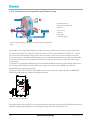
2.2 Principleofoperation
1
4
2
3
Figure 2.1 R otor principle
1. Process air
2. Dr y air
3. Reactivation air
4. Wet air
The desiccant rotor is the adsorption dehumidifying component in the unit. The rot or structure is
comprised of a large number of small air channels.
The desiccant rotor is made of a composite material that is highly effective in attracting and retaining water
vapour. T he rotor is divided in two zones. The airflow to be dehumidified, process air, passes through the
largest zone of the rotor and then leaves the rotor as dry air. Since the rotor rotates slowly, the incoming air
always meets a dry zone on the rotor, thus creating a continuous dehumidification process.
Theairflow tha t is used to dry t he rotor, r e a c tivation air, is heated. The reactivation air passes through
the rotor in the opposite direction to the process air and leaves the rotor a s wet air (warm, moist air). This
principle enables t he dehumidifier to work effectively, even at freezing temperatures.
6
Dehumidifierdesign
190TEN–1090–G1412

A
4
A
3
A
2
A
1
A
5
A
6
A
7
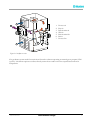
Figur e 2.2 Airflow overview
1. Process air
2. Dry air
3. Reactivation air
4. We t air
5. Reactivation fan
6. Rotor
7. Process fan
The gas burner system used for reactivation is based on a burner operating on natural gas or propane/LPG
(option). The burner operates as a direct fired system to heat outdoor air to the required reactivation air
temp erature.
190TEN–109 0–G1412
Dehumidifierdesign
7

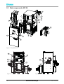
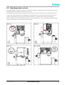
2.3 Maincomponents,MX²30
4
14
3
1
2
7
8
10
12
11
15
5
16
13
17
6
9
Figure 2.3 Exploded view
20
21
15
22
19
18
Figure 2.4 Front view
23
6
Figur e 2.5 Rear view
8
Dehumidifierdesign
190TEN–1090–G1412

Item No.
Description
1.
Reactivation fan
2.
Filter, reactivation air
3. Filter, process air
4.
Gas bur ner unit
5.
Cooling fan with filter
6.
Gas train with GasMultiBloc control unit
7.
Filter, cooling fan
8.
Inspection glass
9. Connector, RJ45
10.
Main power switch
11. Pressure sensor
1)
12.
Process fan
13.
Rotor
14. Drive motor, rotor
15.
Electrical panel
16.
Control syste
mdisplay
17.
Control panel
18.
Burner safety control unit
19.
Pressure switch for reactivation air
20.
Filter guard
21.
Sensor, rotor stop
22.
Duct, bypass damper
1)
23.
Gas shut-off valve
*
Safety thermostat (HTCO)
1)
Option
* Item not illlustrated, see F igure 2.16 .
Table 2.1 Main components, MX² 30
190TEN–109 0–G1412
Dehumidifierdesign
9

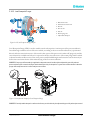
2.4 Maincomponents,MX²35–95
10
9
3
1
12
4
5
7
8
11
16
17
18
13
14
15
6
2
Figure 2.6 Exploded view
3
22
23
26
25
24
20
19
21
Figure 2.7 Front view
27
28
17
Figure 2.8 Rear view
10
Dehumidifierdesign
190TEN–1090–G1412

Item No.
Description
1.
Control system display
2.
Control panel
3.
Process fan
4.
Duct, bypass damper
1)
5. Duct, p urge, right
1)
6.
Safety thermostat (HTCO)
7.
Electrical panel
8.
Drive motor, rotor
9.
Rotor cassette
10.
Duct, purge, left
1)
11.
Filter guard
12.
Plate, bypass
13. Filter, process air
14.
Reactivation fan (left)
2)
15. Reactivation fan
16.
Filter, reactivation air
17.
Gas train with GasMultiBloc control unit
18.
Gas burner unit
19.
Pressure switch for r eactivation air
20.
Burner safety control unit
21.
Electrical panel
22.
Connector, RJ45
23. Main power switch
24
Safety thermostat with reset button
25. Pressure sensor
1)
26. Sensor, rotor stop
27.
Inspection glass
28.
Gas shut-off valve
1)
Option
2)
Only used for reverse d assemblies
Table 2.2 Main c omponents, MX² 35–95
190TEN–109 0–G1412
Dehumidifierdesign
11

2.5 Gasburnerunit
Direct fired gas burners are used on all MX²-series dehumidifiers. T he burner operates on natural gas or
propane (option) and uses the reactivation air to supply the oxygen necessary for combustion. A correct
reactivation airflow is t h erefore essential to e n sure that the burner operates efficiently.
For optimal performance, the reactivation air must contain minimum 20 % oxygen. Bur ner return air cannot
be used. To maintain the efficiency of the unit, it is also important that the outlet for t he wet air is correctly
placed. This is to prevent the wet air contaminating the reactivation air.
The burner is mounted in the reactivation airflow. The gas is mixed with the reactivation air wh ich penetrates
into the space between the V-shaped mixing plates.
A spark ignitor and flame detection probe are mounted in the burner combustion chamber. The flame
detection probe uses the ionisation principle to send a flame signal to the burner safety control unit.
The working principle w ith constant airflow and pressure drop across the bur ner ensures that the
combustion gase s and reactivation air mix well.
4
2
1
6
3
5
Figure 2.9 Gas burner assembly
1. Mixing plates
2. End p lates
3. Flame detection probe
4. Ignition transformer
5. Spark ignitor
6. Burner head
12
Dehumidifierdesign
190TEN–1090–G1412

6
8
2
4
5
3
7
1
Figure 2.10 Side view of the b urner combu stion chamber
1. Burner head port
2. Flame detection probe
3. Mixing plates
4. Spark ignitor
5. Spark ignitor connection plug
6. Gas pipe
7. Flame detection connection plug
8. Silicone cable
2.6 GasMultiBloc
®
contr
olunit
2.6.1 Principleofoperation
A GasMultiBloc control unit in the gas train controls and m onitors the gas pressure and flow. The
GasMultiBloc contains an adjustable flow regulator which in conjunction with an exter nal control valve
enables automatic modulation of the burner capacity, see Figure 2.12 .
L1
N
3
4
V1
V2
5
1
2
N
L1
Figure 2.11 Diagram, GasMultiBloc
3.
Gas filter
N.
Neutral
4.
Low pressure switch
V1.
Solenoid valve
5.
Gas pres
sure regulator
V2.
Solenoid valve (including adjustable flow regulator)
L1.
Phase
Theg asflows into the GasMultiBloc, passes through the gas filter (3) and the adjustable low pressure switch
(4). Valves V1 and V2 are energised by the same control signal and open simultaneously. The pressure is
set by the pressure regulator (5). The maximum allowed gasflow (max. bur ner capacity) is restricted by
the adjustable flow regulator included in valve V2.
190TEN–109 0–G1412
Dehumidifierdesign
13

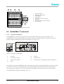
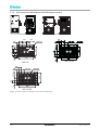
2.6.2 Overview
1
8
5
2
3
4
6
7
9
A
B
Figur e 2.12 Overview, GasMultiBloc
A.
Flow from gas supply
B.
Flow to gas burner
1.
Gas shut-off valve
6.
Cove r for gas filter
2.
Low pressure switch
7.
Screw for cover
3.
Pressure test point for gas supply (P
e
)
8.
Pressure test point (before
valve V1)
4.
Maximum flow adjustment knob
9. Gas control valve with
actuator
5.
Pressure test point (after valve V1)
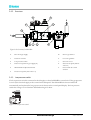
2.6.3 Lowpressureswitch
The low pressure switch is connected to the inlet pipe on the GasMultiBloc control unit. If the gas pressure
is too low, the electrical supply to the control unit is disrupted. T he dehumidifier is then switched off
automatically, and an alarm for low gas pressure is shown on the control panel display. T he low pressure
switch has a range of 5 to 150 mbar. Standard setting is 15 mbar.
Made in Germany
IP 54
5
90
10
20
30
50
70
110
130
mbar
GW 50 A5
pmax.= 500 mbar Gas
~(AC) 50-60Hz 10A 250V
15T70
ID.No:CE-0085
AO 0012
150
Figur e 2.13 Low pressu re switch
14
Dehumidifierdesign
190TEN–1090–G1412

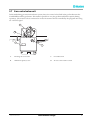
2.7 Gascontrolvalveunit
In this m o dulating gas reactiva tion heater system , there is a c ontrol va lve fitted in the g as line between the
GasMultiBloc and the gas burner. This makes it possible to vary the g a s flow and burner capacity during
operation. The control valve is connected to an electric actuator that is controlled by the program unit using
a0–10VDCsignal.
0
1
0
A
B
C
D
A.
Rotating valve extension
C.
Override button
B.
Minimum capacity screw D.
Inverse contro
lactionswitch
190TEN–109 0–G1412
Dehumidifierdesign
15

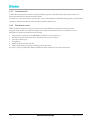
2.8 Burnersafetycontrolunit
The control unit ensures safe ignition, start -up and shut-dow n during both nor mal operation and if a fault
occurs.
It is equipped with a self-checking flame monitoring circuit that controls t he combustion process. T he flame
monitoring circuit applies the necessary safety measures if the flame signal occurs to soon or not at all, and if
any type of fault in the flame detector, detector cables or flame signal amplifier occurs.
Faults that are detected during the start-up procedure or normal operation result in shutdown. Operation is
then preven ted u ntil the fault is remedied and the bur ner safety control unit is reset using the mode switch.
1
2
Figure 2.14 Bur n er con
tr ol unit
1. Prog ramme indicator
2. Warning lamp for shut
down/lockout switch
See the wiring diagram for more inform ation on the control unit connections.
2.8.1 Operation–start-upsequence
When power is applied to the relay and the start contact is closed, the burner control unit runs to ‘start’
position. When the burner control unit receives a star t ing signal from the PLC, an automatic check is carried
out between the burner control unit a nd the pressure switch for the reactivation airflow. This is to ensure
that the pressure sw itch contact is open. If the contact is open, the reactivation air fan can star t .
■
If the pressure switch contact is closed (in the 'no air' position), the control unit does not star t.
Shortly after the reactivat ion air f an starts, the bur ner control unit checks that the pressure switch contact has
closed (combustion air supply available).
■
If the contact has not closed, the contr ol unit abor ts the burner start up .
When the flow sw itch contact is closed, the purge time start. For about 30 seconds, all remaining gasses are
purged from the c ombustion chamber. After the purge time has been terminated, the ignition is started.
A few seconds later the g as supply valves (V1 and V2) are supplied with power. In case a flame has been
established and detected by the flame detection probe, the relay continues to operate until it has reached its
r un position. If no flame is present or not detected, the relay generates a burner lock out, closing (V1 and
V2) immediately. The program indicator s tops in the position where the problem occur red as help for fault
tracing.
16
Dehumidifierdesign
190TEN–1090–G1412
Page is loading ...
Page is loading ...
Page is loading ...
Page is loading ...
Page is loading ...
Page is loading ...
Page is loading ...
Page is loading ...
Page is loading ...
Page is loading ...
Page is loading ...
Page is loading ...
Page is loading ...
Page is loading ...
Page is loading ...
Page is loading ...
Page is loading ...
Page is loading ...
Page is loading ...
Page is loading ...
Page is loading ...
Page is loading ...
Page is loading ...
Page is loading ...
Page is loading ...
Page is loading ...
Page is loading ...
Page is loading ...
Page is loading ...
Page is loading ...
Page is loading ...
Page is loading ...
Page is loading ...
Page is loading ...
Page is loading ...
Page is loading ...
Page is loading ...
Page is loading ...
Page is loading ...
Page is loading ...
Page is loading ...
Page is loading ...
Page is loading ...
Page is loading ...
Page is loading ...
Page is loading ...
Page is loading ...
Page is loading ...
Page is loading ...
Page is loading ...
Page is loading ...
Page is loading ...
Page is loading ...
Page is loading ...
Page is loading ...
Page is loading ...
Page is loading ...
Page is loading ...
Page is loading ...
Page is loading ...
-
 1
1
-
 2
2
-
 3
3
-
 4
4
-
 5
5
-
 6
6
-
 7
7
-
 8
8
-
 9
9
-
 10
10
-
 11
11
-
 12
12
-
 13
13
-
 14
14
-
 15
15
-
 16
16
-
 17
17
-
 18
18
-
 19
19
-
 20
20
-
 21
21
-
 22
22
-
 23
23
-
 24
24
-
 25
25
-
 26
26
-
 27
27
-
 28
28
-
 29
29
-
 30
30
-
 31
31
-
 32
32
-
 33
33
-
 34
34
-
 35
35
-
 36
36
-
 37
37
-
 38
38
-
 39
39
-
 40
40
-
 41
41
-
 42
42
-
 43
43
-
 44
44
-
 45
45
-
 46
46
-
 47
47
-
 48
48
-
 49
49
-
 50
50
-
 51
51
-
 52
52
-
 53
53
-
 54
54
-
 55
55
-
 56
56
-
 57
57
-
 58
58
-
 59
59
-
 60
60
-
 61
61
-
 62
62
-
 63
63
-
 64
64
-
 65
65
-
 66
66
-
 67
67
-
 68
68
-
 69
69
-
 70
70
-
 71
71
-
 72
72
-
 73
73
-
 74
74
-
 75
75
-
 76
76
-
 77
77
-
 78
78
-
 79
79
-
 80
80


Ask a question and I''ll find the answer in the document
Finding information in a document is now easier with AI
Related papers
-
Munters MX2S Owner's manual
-
-
-
-
-
-
-
-
-
Other documents
-
CDA 3B10BL Datasheet
-
 Dehutech 2400 User manual
-
 SnapSafe 75905 Operating instructions
-
 Seaira Global WatchDog NXT60 Operating instructions
-
ETS 5112 User manual
-
Condair 52 Dehumidification Planning Owner's manual
-
 PoolPak PCP Series Start-Up Procedures
-
 Trebor Q-SERIES Operation & Maintenance Manual
-
 Teledyne 8800P User manual
-
ABB LWT300 series User manual


