Bacharach ADM800 User manual
- Category
- Carbon monoxide (CO) detectors
- Type
- User manual
This manual is also suitable for

AGM300 / ADM800
Ammonia Gas Monitoring System
Instruction 3015-4275
Installation / Operation / Maintenance
Rev. 3 – May 2006
Product Leadership • Training • Service • Reliability
INSPECTION EQUIPMENT
MEASURING EQUIPMENT
61KN

A Instruction 3015-4275
Notice:
Product improvements and enhancements are continuous; therefore the specifications and information
contained in this document may change without notice.
Bacharach, Inc. shall not be liable for errors contained herein or for incidental or consequential damages in
connection with the furnishing, performance, or use of this material.
No part of this document may be photocopied, reproduced, or translated to another language without the prior
written consent of Bacharach, Inc.
Copyright © 2003 − 2006, Bacharach, Inc., all rights reserved.
BACHARACH
®
is a registered trademark of Bacharach, Inc. All other trademarks, trade names,
service marks and logos referenced herein belong to their respective owners.

Instruction 3015-4275 i
Table of Contents
INTRODUCTION..............................................................................................................................................................II
SAFETY PRECAUTIONS .................................................................................................................................................III
WARNING STATEMENTS ........................................................................................ERROR! BOOKMARK NOT DEFINED.
CAUTION STATEMENTS .........................................................................................ERROR! BOOKMARK NOT DEFINED.
HAZARD SYMBOLS ON MONITOR ..........................................................................ERROR! BOOKMARK NOT DEFINED.
FUNCTIONAL OVERVIEW .............................................................................................................................................. V
AGM300 INSTALLATION...........................................................................................................................................1
AGM300 - INSTALLATION CONSIDERATIONS................................................................................................................2
AGM300 - MOUNTING INSTRUCTIONS ..........................................................................................................................3
AGM300 - CONNECTING AIR LINES..............................................................................................................................4
AGM300 - INTERIOR SCHEMATIC .................................................................................................................................6
AGM300 - ELECTRICAL WIRING...................................................................................................................................8
AGM300 - CONNECTING COMMUNICATION DEVICES .................................................................................................10
MULTIPLE AGM’S ......................................................................................................................................................12
CONNECTING TO A BUILDING MANAGEMENT SYSTEM ................................................................................................12
AGM300 - PC SOFTWARE...........................................................................................................................................13
AGM300 - CURRENT LOOP INTERFACES.....................................................................................................................16
AGM300 - CONNECTING EXTERNAL ALARMS ............................................................................................................17
ADM800 INSTALLATION .........................................................................................................................................19
ADM800 - INSTALLATION CONSIDERATIONS..............................................................................................................20
ADM800 - MOUNTING INSTRUCTIONS ........................................................................................................................21
ADM800 - INTERIOR SCHEMATIC ...............................................................................................................................22
ADM800 - ELECTRICAL WIRING.................................................................................................................................24
ADM800 - COMMUNICATION CONNECTIONS ..............................................................................................................26
ADM800 - CONNECTING EXTERNAL ALARMS ............................................................................................................28
ADM800 OPERATION ...............................................................................................................................................29
ADM800 - OVERVIEW ................................................................................................................................................30
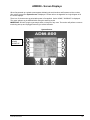
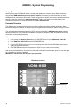
ADM800 - SCREEN DISPLAYS.....................................................................................................................................31
ADM800 - SYSTEM PROGRAMMING ...........................................................................................................................32
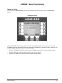
ADM800 - SETUP PROGRAMMING ..............................................................................................................................33
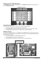
AGM300 - SETUP PROGRAMMING ..............................................................................................................................37
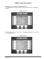
ADM800 - ZONE SETUP PROGRAMMING.....................................................................................................................41
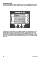
GENERAL OPERATION .................................................................................................................................................44
WORKING WITH ALARMS ............................................................................................................................................50
WORKING WITH THE TREND SCREEN...........................................................................................................................53
WORKING WITH SYSTEM FAULTS ................................................................................................................................54
WORKING WITH THE CALIBRATION SCREEN................................................................................................................57
WORKING WITH THE DIAGNOSTIC SCREEN..................................................................................................................59
SERVICE MODE ...........................................................................................................................................................61
APPENDIX ...................................................................................................................................................................63
AGM300 / ADM800 MAINTENANCE ..........................................................................................................................64
OPTIONAL ACCESSORIES .............................................................................................................................................65
ADM800 - LOGIC DIAGRAM .......................................................................................................................................66
RS-485 COMMUNICATION PROTOCOL.........................................................................................................................67
AGM300 MODBUS RTU OPERATION .......................................................................................................................68
WARRANTY AND SERVICE ....................................................................................................................................81
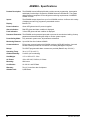
AGM300 - SPECIFICATIONS ........................................................................................................................................83
ADM800 - SPECIFICATIONS ........................................................................................................................................84

ii Instruction 3015-4275
Introduction
How to Use This Manual
Thank you for investing in a BACHARACH Ammonia Gas Monitoring System.
This manual provides important information on how to install, operate, and service the AGM300 Ammonia Gas
Monitor and ADM800 Ammonia Display Module.
Please Read this Manual Carefully Before Use
If you have a working knowledge of gas monitors, you will find this manual useful as a reference tool. If you are
new to the use of gas monitors, you can educate yourself about the principles of gas detection and the proper
operation of this device by reading this manual thoroughly.

Instruction 3015-4275 iii
Safety Precautions
AC Power Supply
Ensure the source voltage matches the voltage of the product before energizing the equipment. It is highly
suggested that the AGM300 be placed on a separate circuit (with UPS or surge protection).
• A switch or circuit-breaker shall be included in the building installation
• It shall be in close proximity to the equipment and within easy reach of the operator
• It shall be marked as the disconnecting device for the equipment
Protective Grounding
Under no circumstances should this equipment be operated without connection to a protective ground. Doing
so poses a potential shock hazard and is also a violation of electrical safety standards applicable to this type
of equipment.
Explosive Atmosphere
Do not operate this equipment in the presence of flammable liquids, vapors or aerosols. Operation of any
electrical instrument in such an environment constitutes a safety hazard.
Proper Exhaust Venting
It is imperative that the exhaust port on this instrument be properly vented as described in this manual. Failure
to do so constitutes a safety hazard.
Working Inside the Instrument
Extreme care should be exercised when accessing the interior of this instrument. Only qualified electrical
maintenance personnel should perform connections and adjustments. Always de-energize the power supply
before working inside the instrument.
Modifications to the Instrument
Under no circumstances should this instrument be modified without written consent from Bacharach, Inc.
Changes or modifications to this instrument, not expressly approved, will void the warranty.
In Case of Malfunction
Do not continue to use this equipment if there are any symptoms of malfunction or failure. In the case of such
occurrence, de-energize the power supply and contact a qualified repair technician or the nearest Bacharach
Service Center. ONLY provided knockouts are to be used for electrical and communication wiring. Drilling into
the box will void the warranty.
Fusing
AGM300, 120 VAC Input, Power Supply P/N 3015-3167
F1: 0.5 A, 250V Fast Acting, 5mm x 20mm, P/N 604-2538
F2: 250 mA, 250V Fast Acting, 5mm x 20mm, P/N 604-2537
F3: 5 A, 250V Fast Acting, 5mm x 20mm, P/N 604-2539
F4: 63 mA, 250V Fast Acting, 5mm x 20mm, P/N 604-2535
AGM300, 230 VAC Input, Power Supply P/N 3015-3161
F1: 250 mA, 250V Fast Acting, 5mm x 20mm, P/N 604-2537
F2: 125 mA, 250V Fast Acting, 5mm x 20mm, P/N 604-2536
F3: 5 A, 250V Fast Acting, 5mm x 20mm, P/N 604-2539
F4: 32 mA, 250V Fast Acting, 5mm x 20mm, P/N 604-2534
ADM800
F1 & F2: 1 A, 250VAC, Fast Acting, 5mm x 20mm, P/N 3015-4011

iv Instruction 3015-4275
Safety Precautions (Cont.)
Installation Category
Installation Category II, Pollution Degree II, as defined by UL.
Altitude Limit
2,000 meters
Cleaning
USE a dry cloth to clean the outside of the case. DO NOT use soap and water.
Warning Statements
The use of the word WARNING in this manual denotes a potential hazard associated with the use of this
equipment. It calls attention to a procedure, practice, or condition, or the like, which if not correctly performed or
adhered to, could result in personal injury or death.
Caution Statements
The use of the word CAUTION in this manual denotes a potential hazard associated with the use of this
equipment. It calls attention to a procedure, practice, condition, or the like, which if not correctly performed or
adhered to, could result in damage to the equipment.
Hazard Symbols on Monitor
This symbol indicates the need to consult this operating instruction
manual when opening the enclosure.
WARNING: A potential risk exists if the operating instructions are not
followed.
This symbol indicates the presence of electric shock hazards when
the enclosure is opened.
WARNING: To avoid risk of injury from electric shock, do not open
the enclosure when power is applied.

Instruction 3015-4275 v
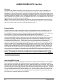
Functional Overview
General Description
The AGM300 is designed to support compliance to federal, state and local safety codes governing ammonia
gas emissions. Avoiding significant ammonia gas loss reduces equipment replacement costs, maintains
equipment efficiency, promotes safety, and protects the environment.
The AGM300 provides for the continuous monitoring of ammonia gas levels in up to 16 separate test zones.
Each zone can be independently programmed to identify leak (small), spill (medium), or evacuation (large)
levels of gas. The instrument also retains a log of previous readings that can be easily accessed for analysis.
An audible alarm and large LED indicators are provided to signal alarm conditions, and relay contacts are
provided for the connection of external alarm devices. The system also includes two 4–20 mA current loop
interfaces (optional) for connection to external devices.
The AGM300 requires only minor periodic maintenance such as the occasional replacement of filters. The
instrument incorporates active diagnostics that continuously monitor the system for proper operation. An LED
indicator is provided to indicate system malfunctions, and fault codes are displayed that enable the operator to
identify the source of the fault.
Communication Options
The AGM300 features full two-way communications via an RS-485 interface. MODBUS RTU is the
communication protocol standard. The instrument can be connected directly to a Building Management System
or it may be operated as a stand-alone system using the ADM800 Ammonia Display Module.
An RS-232C port is also provided for connection to a PC. This enables the AGM300 to be setup from a
personal computer.
Please refer to the Appendix for a more complete discussion of communication protocols.
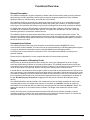
Suggested Location of Sampling Points
At the point of an ammonia gas leak the gas is nearly pure. As the gas is dispersed into the air, the gas
molecules diffuse causing a dilution of the original concentration. The AGM300 measures the ammonia gas
concentration at the precise point the sample is collected. Therefore, if the termination of the collection line is
not at the exact point of the gas leak, then the unit will read a diluted mixture of the gas and air.
It should also be noted that when ammonia gas is cold it is heaver than air and settles below the leak point, but
as the gas warms to room temperature it becomes lighter than air and tends to collect above the point of a leak.
Consequently, sampling points should ideally be located as close as possible to the source of potential leaks. If
this is impractical, then the alarm set points should be adjusted for that zone to compensate for the dilution of
the gas. DO NOT plug any of the zones. Plugging a zone will give the monitor a false indication during
start up.
The AGM300 should be centrally located in the mechanical room and be readily accessible for easy visual
monitoring and servicing. Air sample tubing may be run in lengths up to 500 feet. The fresh air purge line
should draw from an area that does not contain any ammonia gas and cannot exceed 300 feet in length. The
exhaust line should run to an out side location if possible. The length of the exhaust line cannot exceed
300 feet.
Ideally, two to three pick up points spaced around each chiller will provide sufficient coverage. It may be
necessary to perform a “smoke” test of the mechanical room to determine the best locations. The smoke test
would provide the pattern of air currents present in the mechanical room.

vi Instruction 3015-4275
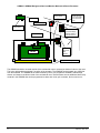
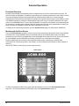
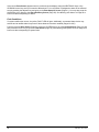
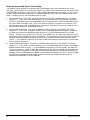
AGM300 / ADM800 Refrigerant Gas Leak Monitor Mechanical Room Placement
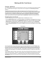
The ADM800 should be mounted outside of the mechanical room or at least just inside of a door to the room.
This is the “split architecture design” for safety of the operator. The ADM800 can be located up to 4500 feet
from the AGM300. The ADM800 is the main interface by which you program the AGM300, acknowledge
alarms, and observe conditions inside of the mechanical room. Note that there are two additional alarm relay
contacts in the ADM800 that can be programmed to alarm with “leak, spill, evacuate, fault or monitor on”.
AGM300
Ammonia
Gas
Monitor
Outside Hallway
Machine Room
Sample Inlet Pickup Points
Chiller
Sample Inlet
Pickup Point
Aux. Horn/Strobe
Remote Alarm
Fresh air purge
from area away
from ammonia
gas
Exhaust Fan
ADM800
Ammonia Display
Module outside of
mechanical room

Instruction 3015-4275 1
AGM300 Installation
Upper Mounting
Bracket
Lower Mounting
Br
ac
k
et
Water Trap
STANDARD ACCESSORIES FOR A 4 POINT SYSTEM
5 Line-End Filters (P/N 3015-3420)
AGM300/ADM800 Instruction Manual (P/N 3015-4275)
LED
Indicators

2 Instruction 3015-4275
AGM300 - Installation Considerations
Locating the Monitor
The AGM300 should be centrally located in the facility and should be easily accessible for visual monitoring and
servicing. Intake sample lines can be up to 500 feet in length, but it is important to remember that sampling
cycle time is proportional to the total number and length of individual sample lines.
Dirt, grease, and oils can adversely affect the operation of the AGM300. The monitor should be installed out of
direct sunlight in a clean, dry area that is not subject to temperature or humidity extremes. Installation of the
monitor in a mechanical room is acceptable provided reasonable environmental conditions exist. If there is a
question, consider installing the unit outside of the mechanical room in a cleaner area of the facility.
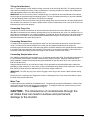
Warnings and Cautions
WARNING – Drilling holes in the AGM300 and
ADM800 enclosure will void the warranty. Please
use knockouts provided for electrical connections.
WARNING - Do not operate this equipment in the
presence of flammable liquids, vapors or aerosols.
Operation of any electrical instrument in such an
environment constitutes a safety hazard.
WARNING - Always de-energize the power supply
before working inside the instrument.
CAUTION - The AGM300 contains sensitive
electronic components that can be easily damaged.
Be careful not to touch or disturb any of these
components.
Inspection
The AGM300 has been thoroughly inspected and tested prior to shipment from the factory. Nevertheless, it is
recommended that the monitor be re-checked prior to installation. Inspect the outside of the enclosure to make
sure there are no obvious signs of shipping damage. Open the door latches and inspect the interior of the
instrument for loose components that may have become dislodged during shipment. If damage is discovered,
please contact the nearest Bacharach Service Center for assistance.

Instruction 3015-4275 3
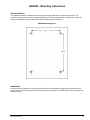
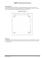
AGM300 - Mounting Instructions
Screw Locations
The AGM300 should be installed plumb and level and securely fastened to a rigid mounting surface. The
enclosure utilizes keyhole mounting brackets designed for #12 pan head fasteners. Locate the four screws as
shown in the diagram and leave the screw heads protruding approximately 3/16".
AGM300 Mounting Specs
Installation
Hold the monitor flat against the mounting surface and allow it to slide down engaging the screw heads in the
keyhole slots of the mounting brackets. Adjust the screws as necessary to hold the monitor securely against the
mounting surface.

4 Instruction 3015-4275
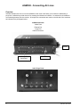
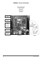
AGM300 - Connecting Air Lines
Overview
Individual sample lines are run from the AGM300 to each area of the facility to be monitored. Additionally, a
purge line is installed to provide clean air for resetting the infrared zero baseline. An exhaust line is installed to
vent residual gas away from the monitor. All sample line connections are made on the left side of the enclosure
as indicated in the photograph below.
AGM300 Side View
Intake Ports
Exhaust Port
Purge Port
RS-232 Connector
Inlet / Purge Ports
RS-232
Inlet/Purge Ports
(see below)
Exhaust Port

Instruction 3015-4275 5
Tubing Considerations
Use ¼" outside diameter (0.040" wall) flex tubing is used for all air lines (P/N 304-2742). The tubing should be
clean and free of residual moisture or other contaminants. The tubing should be cut cleanly with a sharp knife
and care should be taken not to distort the tubing end.
IMPORTANT: Due to the reactive nature of ammonia gas, it is important to use materials that will not absorb
ammonia gas as it passes though the sampling system. The use of unauthorized tubing or any other materials
in the gas sampling stream may lead to erroneously low readings.
To connect the air lines to the monitor simply push the tubing firmly onto the connector. All tubing bends should
have a radius of no less than 5" to assure proper airflow. If kinks or obstructions occur in any of the air lines the
instrument may not function properly.
Connecting Purge Line
A purge line is required to draw fresh air into the instrument and should not exceed 300 feet in length. It is
advisable to terminate the line outdoors, provided the input is not exposed to rain, snow, ice, exhaust fumes, or
other airborne contaminates. If an outdoor installation is impractical, the line should be run to an area inside the
facility that you are certain is not contaminated with ambient ammonia gas. A line-end filter (P/N 3015-3420)
should be attached to the end of the purge line.
Connecting Exhaust Line
An exhaust line is required to vent gas samples away from the instrument and should not exceed 300 feet in
length. The exhaust line should terminate in a location that is completely isolated from the purge line
termination point and other areas of the facility that will be monitored. Ideally this line should terminate outdoors
in a location that is not exposed to the elements. This line does not require a line-end filter. If the exhaust line
terminates outside the building, position the tubing so that no water or moisture can enter it.
Connecting Sample Intake Lines
The AGM300 is designed to accommodate up to 16 separate sample intake lines. The standard configuration of
the unit includes one manifold of 4 intake connectors and 1 purge connector. Additional manifolds can be
easily installed to increase monitoring capacity (field installation kit part P/N 3015-3419, and 4 zone line end
filter kit P/N 3015-3411).
Sample intake lines can be up to 500 feet in length. All line terminations should be positioned to reduce the
possibility of mists, aerosols, oil, water, dust, or other contaminates being drawn into the instrument. A line-end
filter (P/N 3015-3420) should be attached to the end of each sample intake line.
IMPORTANT: DO NOT plug any of the zones. Plugging a zone will give the monitor a false indication during
start up.
Please refer to the earlier Section Suggested Location of Sampling Points to learn more about where to place
the ends of the sample intake lines.
Water Trap
A water trap has been installed as a standard feature. The water trap prevents condensation or moisture from
entering the infrared device and causing serious damage. To empty the water trap, loosen the wing nut and
allow water to drain – be sure to retighten the wing nut.
CAUTION - The introduction of contaminants through the
air intake lines can result in serious and permanent
damage to the monitor.

6 Instruction 3015-4275
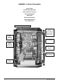
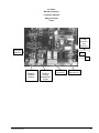
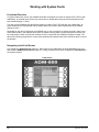
AGM300 - Interior Schematic
Primary Filter
Intake Manifold Solenoids
Intake Solenoid Connectors
Power Supply Board
Main Board
Microcontroller Board
Infrared Optical Bench
Gas Sample Pump
Primar
y
Filter
(
P/N 3015-3071
)
Intake
Manifold
Solenoids
Gas Sample
Pump
Infrared
Optical Bench
Microcontroller
Board
Main Board
Power Supply
Board
120 or 230 VAC
Determined by
Sales Order
Intake
Manifold
Solenoid
Connectors

Instruction 3015-4275 7
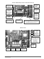
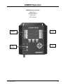
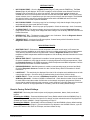
AC Power / RS-485 / Relay Connector / 4-20 mAdc Current Loop
Switches / Fuses
Auxiliary AC Out Connector T2
(Used to Supply AC power to Alarm Devices)
(Overload Protected by Fuse F3)
AC IN
Connector
T1
Location of
AC Input
Line Filter
(230 VAC
Units Only)
Dual 4-20 mAdc
Outputs
(Signal Out Only)
DO NOT APPLY
POWER!
RS-485
Connector
Relay Connector
Alarm 1, 2, 3, Fault
4–20 mAdc
Interface Board
(Optional)
AC Power
ON/OFF
Switch
Ground Stud
Factory
Default
Terminator
IN / OUT
CPU
Reset
Node Address
Switches
AC Power
ON/OFF
Switch
F1
F2
AGM300
Fuses
(Refer to
Maintenance
Section for
values Page 64)
F3
Connects to Aux. AC Out
Connector T2
5 Amp 250VAC
(P/N 604-2539)
F4

8 Instruction 3015-4275
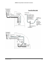
AGM300 - Electrical Wiring
It is highly recommended that the AGM300 be connected directly to the AC power source, preferably on its own
circuit. The connection should be completed with a UL rated multi-conductor wire (14-18 AWG).
Locate service knockouts on exterior of enclosure and install electrical conduit in the typical manner.
The AGM300 is available in either a 120 or 230 VAC configuration. The unit’s AC voltage rating is marked on
the outside of the enclosure. Do one of the following to connect the AC power leads and ground:
• 120 VAC Installation
Locate the AC IN connector T1 and the Ground Stud on the inside of the enclosure (Page
7).
Remove the AC IN connector from the Power Supply board, and then secure the incoming AC power line
(black) and neutral (white) wires to this connector as shown in the following illustration. Carefully plug the
connector back onto the circuit board.
Using the supplied crimp-on ring terminal, washers, and nuts, connect the AC input ground wire (green) along
with the ground wire connected to the enclosure’s lid to the monitor’s Ground Stud.
• 230 VAC Installation
Locate the AC Input Line Filter’s black and white wires, and the Ground Stud on the inside of the enclosure
(Page
7).
Using wire nuts, secure the incoming AC power Line 1 (black) and Line 2 (white) wires to the AC Input Line
Filter as shown in the following illustration.
Using the supplied crimp-on ring terminal, washers, and nuts, connect the AC input ground wire (green) along
with the ground wire connected to the enclosure’s lid to the monitor’s Ground Stud.
WARNING – Drilling holes in the AGM300 enclosure will
void the warranty. Please use knockouts provided for
electrical connections.
WARNING - Electrical installation should be performed
by a certified electrician and should comply with all
applicable local, state, and federal electrical safety
codes.
WARNING - Under no circumstances should this
instrument be operated without connection to a
protective ground. Doing so poses a potential shock
hazard and is also a violation of electrical safety
standards applicable to this type of equipment.
• A switch or circuit-breaker shall be included in the building installation
• It shall be in close proximity to the equipment and within easy reach of the operator
• It shall be marked as the disconnecting device for the equipment

Instruction 3015-4275 9
AGM300 AC Input Power and Ground Connections

10 Instruction 3015-4275
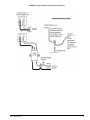
AGM300 - Connecting Communication Devices
Ammonia Display Module (ADM800) Connection
The AGM300 is connected to the ADM800 using a shielded twisted pair instrument cable. The maximum
distance between the farthest away AGM300 and ADM800 is 4500 feet.
Use any of the remaining service knockouts to gain access to the interior of the monitor. The RS-485
communication wiring between the AGM300 and ADM800 must be connected in the following manner:
Locate the RS-485 connector in the AGM300 (Page
7). Connect one lead of a twisted shielded pair to the
“B” connection point (the far left point), note the wire color. Connect the second wire to the “A” connection
point (the middle), note the wire color. Connect the ground to the “GND” connection point
Locate the RS-485 connector marked “TO MONITORS” in the ADM800 (Page
23). This connector is
located on the far-left bottom of the ADM800 PC board. Make the wire run to the ADM800 and connect the
twisted shielded pair to the RS-485 TO MONITORS connector using the same color code as used on the
AGM300.
Integrating with Building Management Systems
The AGM300 may be connected directly to a Building Management System using a shielded twisted pair cable.
The cable from the Building Management System is connected to the RS-485 connector inside the AGM300.
MODBUS RTU is the standard communication protocol.
Use any of the remaining service knockouts to gain access to the interior of the monitor. Locate the RS-485
connector and remove it from the circuit board. Secure the wire leads to the connector orienting them as shown
in the diagram below. Check to make sure that the polarity matches the wiring to the Building Management
System. When you are through securing the connections, carefully plug the connector back onto the circuit
board.
Larger Integrated Systems
You may also connect the AGM300 to a Building Management System through an ADM800. In this case, first
connect the AGM300 to the ADM800 as described above. Then, follow the instructions under the heading
ADM800 – Communications Connections on Page
26 for information on how to connect the ADM800 to a
Building Management System.
RS-485 Connector

Instruction 3015-4275 11
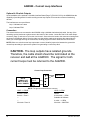
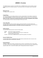
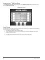
Changing Terminator Settings
The terminator switch is shipped from the factory in the terminated or “IN” position. This is the correct setting if
the AGM300 is connected as a single device, or it is the last device on the network chain. If the AGM300 is
being installed in the middle of a network, the terminator must be moved to the “OUT” position.
Locate the switch and determine its position. If it needs to be moved, slide the switch to the appropriate
position.
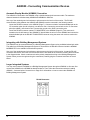
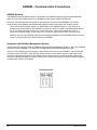
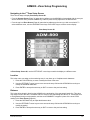
Node Address DIP Switch Settings
(Refer to Multiple AGM's and Connecting to a Building Management System)
Each AGM300 on the network must have a distinct node address. The node address may be set from 1 to 15.
Four dip switches numbered 1, 2, 4, 8 on the main circuit board are used to define this value by setting the
correct combination of dip switches to their ON positions. The node address is the sum of the switch numbers
that are ON.
Example: - For node address “5” switches 1 and 4 are ON.
- For node address “13” switches 1, 4, & 8 are ON.
Power must be cycled to elect this change.
Personal Computer
(Refer to AGM300 PC Software Section)
The AGM300 may be connected to a personal computer using the RS-232 interface on the left side of the
enclosure.
Software will be provided upon request or as a download from:
http://www.bacharach-inc.com/downloads.htm.
Network Node
Address
Switch
Terminator
Switch
IN OUT

12 Instruction 3015-4275
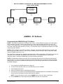
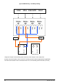
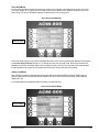
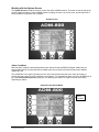
Multiple AGM’s
MULTIPLE AGM300’S WITH ADM800
NOTE 1: The last AGM300 or ADM800 on either end of the network must have its terminator
in the “IN” position, and all other units must have their terminators in the “OUT” position.
NOTE 2: The total length of the RS-485 cable cannot exceed 4500 feet. (Use instrument
cable 20 gage multi-strand shielded and twisted pair – similar or equal to Belden
cable #8762.)
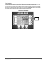
RS-485 CONNECTIONS BETWEEN AGM300’s
NOTE: The terminators in the ADM800 and AGM300 Unit 4 must be in the “IN” position. The
terminators in AGM300 Units 1, 2 & 3 must be in the “OUT” position.
TERMINATOR TERMINATOR TERMINATOR TERMINATOR
“OUT” “OUT” “OUT” “IN”
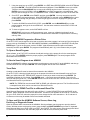
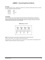
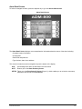
Connecting to a Building Management System
The AGM300 may be connected to a Building Management System via the RS-485 connector. The node
address switch on each AGM300 may be set from “1” to “15” in order to identify itself to the Building
Management System. Note that Building Management Systems set to a “0” or “1” address both respond to
messages from the ADM800 as address “1” therefore you should not have a unit set to “0” and another set to
“1” on the same network.
If the AGM300 network is connected directly to a Building Management System it may not
be connected to the
ADM800. However, the ADM800 has two communication ports, an “upstream” port (labeled TO HOST) and a
“downstream port (labeled TO MONITORS). A BMS node may be connected to the up stream ADM800 port
while the downstream ADM800 port talks to the AGM300’s. In this case, the BMS is talking “through” the
ADM800 to the AGM300’s, but not physically on the AGM300/ADM800 network.
NOTE: If the AGM300 is not at the end of the line in a series connection, then the terminator on the AGM must
be set to “OUT.” Also, each end of the series must have the terminator set to “IN”.
MULTIPLE AGM300'S CONNECTED TO A BUILDING MANAGEMENT SYSTEM
TERMINATOR
“OUT”
TERMINATOR TERMINATOR TERMINATOR TERMINATOR
“IN” “OUT” “OUT” “IN”
AGM300
NODE 1
AGM300
NODE 2
AGM300
NODE 3
AGM300
NODE 4
BMS
AMD800
AGM300
UNIT 2
NODE 2
AGM300
UNIT 3
NODE 3
AGM300
UNIT 4
NODE 4
TERMINATOR
“IN”
AGM300
UNIT 1
NODE 1
RS-485
Page is loading ...
Page is loading ...
Page is loading ...
Page is loading ...
Page is loading ...
Page is loading ...
Page is loading ...
Page is loading ...
Page is loading ...
Page is loading ...
Page is loading ...
Page is loading ...
Page is loading ...
Page is loading ...
Page is loading ...
Page is loading ...
Page is loading ...
Page is loading ...
Page is loading ...
Page is loading ...
Page is loading ...
Page is loading ...
Page is loading ...
Page is loading ...
Page is loading ...
Page is loading ...
Page is loading ...
Page is loading ...
Page is loading ...
Page is loading ...
Page is loading ...
Page is loading ...
Page is loading ...
Page is loading ...
Page is loading ...
Page is loading ...
Page is loading ...
Page is loading ...
Page is loading ...
Page is loading ...
Page is loading ...
Page is loading ...
Page is loading ...
Page is loading ...
Page is loading ...
Page is loading ...
Page is loading ...
Page is loading ...
Page is loading ...
Page is loading ...
Page is loading ...
Page is loading ...
Page is loading ...
Page is loading ...
Page is loading ...
Page is loading ...
Page is loading ...
Page is loading ...
Page is loading ...
Page is loading ...
Page is loading ...
Page is loading ...
Page is loading ...
Page is loading ...
Page is loading ...
Page is loading ...
Page is loading ...
Page is loading ...
Page is loading ...
Page is loading ...
Page is loading ...
Page is loading ...
Page is loading ...
Page is loading ...
-
 1
1
-
 2
2
-
 3
3
-
 4
4
-
 5
5
-
 6
6
-
 7
7
-
 8
8
-
 9
9
-
 10
10
-
 11
11
-
 12
12
-
 13
13
-
 14
14
-
 15
15
-
 16
16
-
 17
17
-
 18
18
-
 19
19
-
 20
20
-
 21
21
-
 22
22
-
 23
23
-
 24
24
-
 25
25
-
 26
26
-
 27
27
-
 28
28
-
 29
29
-
 30
30
-
 31
31
-
 32
32
-
 33
33
-
 34
34
-
 35
35
-
 36
36
-
 37
37
-
 38
38
-
 39
39
-
 40
40
-
 41
41
-
 42
42
-
 43
43
-
 44
44
-
 45
45
-
 46
46
-
 47
47
-
 48
48
-
 49
49
-
 50
50
-
 51
51
-
 52
52
-
 53
53
-
 54
54
-
 55
55
-
 56
56
-
 57
57
-
 58
58
-
 59
59
-
 60
60
-
 61
61
-
 62
62
-
 63
63
-
 64
64
-
 65
65
-
 66
66
-
 67
67
-
 68
68
-
 69
69
-
 70
70
-
 71
71
-
 72
72
-
 73
73
-
 74
74
-
 75
75
-
 76
76
-
 77
77
-
 78
78
-
 79
79
-
 80
80
-
 81
81
-
 82
82
-
 83
83
-
 84
84
-
 85
85
-
 86
86
-
 87
87
-
 88
88
-
 89
89
-
 90
90
-
 91
91
-
 92
92
-
 93
93
-
 94
94


Bacharach ADM800 User manual
- Category
- Carbon monoxide (CO) detectors
- Type
- User manual
- This manual is also suitable for
Ask a question and I''ll find the answer in the document
Finding information in a document is now easier with AI
Related papers
-
Bacharach Multi-Zone User manual
-
-
Bacharach MGS-408 Quick start guide
-
-
-
-
-
-
-