Page is loading ...

www.furuno.co.jp
All brand and product names are trademarks, registered trademarks or service marks of their respective holders.
INMARSAT MINI-C MOBILE EARTH STATION
FELCOM 16
Installation Manual
TABLE OF CONTENTS
EQUIPMENT LISTS.....................................................................................................................iii
SYSTEM CONFIGURATION.......................................................................................................iv
1. MOUNTING THE UNIT..........................................................................................................1
1.1 Antenna Unit.................................................................................................................1
1.2 Communication Unit.....................................................................................................7
1.3 AC/DC Power Supply Unit PR-240 (option) .................................................................7
2. WIRING .................................................................................................................................8
2.1 Antenna Cable Connector at the Terminal Unit............................................................9
3. SETTINGS AFTER THE INSTALLATION ..........................................................................11
3.1 Installing software.......................................................................................................11
3.2 Setting the IMN (Inmarsat Mobile No.).......................................................................15
4. CHANGING POWER SUPPLY SPECIFICATIONS............................................................16
PACKING LISTS.......................................................................................................................A-1
OUTLINE DRAWINGS..............................................................................................................D-1
INTERCONNECTION DIAGRAM.............................................................................................S-1


i
Confirm that the power supply voltage
is compatible with the voltage rating
of the equipment.
Connection to the wrong power supply
can cause fire or equipment damage. The
voltage rating appears on the label at the
rear of the communication unit.
Use the correct fuse.
Use 10 A fuse (defalt setting) for 12 VDC
power supply, or replace the fuse to 5 A
(supplied as spare parts) with 24 VDC.
Use of wrong fuse can result in damage to
the equipment.
Keep the following compass safe
distances.
Standard Steering
Antenna Unit IC-116
Communication Unit IC-216
AC/DC Power Supply Unit
PR-240
SAFETY INSTRUCTIONS
Do not open the equipment
unless totally familiar with
electrical circuits and
service manual.
Only qualified personnel
should work inside the
equipment.
WARNING
Turn off the power at the
mains switchboard before
beginning the installation.
Post a sign near the switch
to indicate it should not be
turned on while the equip-
ment is being installed.
Fire, electrical shock or
serious injury can result if the
power is left on or is applied
while the eqiuipment is being
installed.
ELECTRICAL
SHOCK
HAZARD
0.3 m 0.3 m
0.3 m 0.3 m
0.9 m 0.6 m
Do not approach the ra-
dome closer than 60 cm
when it is transmitting.
Microwave radiation can
cause severe injury or illness.
Radiation level:
10 W/m at 60 cm
2
CAUTION
Attach securely protection
earth to the ship's body.
The protection earth is required
to the power supply to prevent
electrical shock

ii
EQUIPMENT LISTS
Standard Supply
Name Type Code No. Qty Remarks
Antenna Unit IC-116 - 1
Communication Unit IC-216 - 1
Junction Box* IC-315 - 1
w/CP16-02501
SSAS Alert Unit* IC-307 - 2
w/CP16-03101, FP16-00901
Installation Materials
CP16-02101 004-439-060
1 set For 15/30 m antenna cable**
CP16-02111 004-439-070 For 50 m antenna cable**
CP16-02121 004-439-080 For 100 m antenna cable**
TP58A15W-RG58 000-146-252
1
15 m antenna cable
TP5FBAW-5DFBB 000-146-250 30 m antenna cable
8D-FB-CV 000-117-599 50 m antenna cable
12D-SFA-CV 000-138-866 100 m antenna cable
CP16-02401 004-439-540 For communication unit**
Accessories FP16-00700 004-439-550 1 set FD-ROM, FD (FP16-00601)
Spare Parts SP16-01401 004-439-530 1 set Fuse**
Optional Supply
Name Type Code No. Qty Remarks
Cable assy 17JE-573-10 000-127-108 1 For PC connecting
AC/DC Power Supply Unit PR-240 - 1 set w/CP24-00151**
5-pair cable CO-SPEVV-
SB-C 0.2x5P
000-560-452
1
For junction box, 10m
000-103-868 For junction box, 20m
000-103-869 For junction box, 30m
000-132-829 For junction box, 40m
000-132-828 For junction box, 50m
SSAS Alert Unit IC-307 000-043-473 1 w/CP16-03101, FP16-00901
Flush Mounting Kit OP16-28 004-448-010 1 For SSAS alert unit
FFA Modification Kit** OP16-69 004-448-860 1 set
PC Terminal Software OP16-46 004-450-750 1 Russian Language
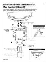
Antenna Mounting Kit CP16-03701 004-555-000 1 set
Antenna Bracket CP16-03702 001-016-260 1 See page D-5.
Antenna Mounting Pipe CP16-03703 001-014-510 1
*: SSAS Specification only.
**: See packing lists at the back of this manual.

iii
SYSTEM CONFIGURATION
Antenna Unit Exposed to Weather
Communication Unit Protected from Weather
Other Units Protected from Weather
PERSONAL
COMPUTER
(PC/AT compatible)
ANTENNA
UNIT
IC-116
COMMUNICATION UNIT IC-216
(with internal GPS receiver)
POWER SUPPLY
100-115/200-230
1φ, 50/60 Hz
: Standard
: Option
: Local Supply
POWER SUPPLY
12-24 VDC
AC-DC
Power Supply
PR-240
POWER
I
O
INMARSAT MINI-C MOBILE EARTH STATION
FURUNO
POWER
LOGIN
TX
ERROR
PRINTER
JUNCTION BOX
IC-315
SSAS ALERT UNIT*
IC-307
SSAS ALERT UNIT*
IC-307
*: At least two SSAS Alert Units are required.
CATEGORY OF UNITS
(Max. 3 units)

iv
This page is intentionally left blank.

1
1. MOUNTING THE UNIT
NOTICE
Do not apply paint, anti-corrosive
sealant or contact spray to coating or
plastic parts of the equipment.
Those items contain organic solvents that
can damage coating and plastic parts,
especially plastic connectors.
1.1 Antenna Unit
Mounting Location
• There should be no interfering object within the line-of-sight to the satellite. Objects within
line-of-sight to a satellite, for example, a mast may block transmission/reception. Mount
the antenna unit as high as possible. This keeps it free of interfering objects and water
spray. The location should be well away from a GPS antenna. A GPS receiver may be
interfered by the Inmarsat C wave.
• If both Inmarsat-B or F ship earth stations are installed, separate the Inmarsat-B/F
antenna at least 8 m.
• Separate the antenna unit from an S-band radar as follows:
HORIZONTAL LINE
Install above this line
PROHIBITED
ZONE
1.5 m
5 m
15
2 m
S-band radar
INSTALLTION
ZONE
2 m
S-band radar and installation area
• The allowable vibration level as specified by Inmarsat is as shown in the table below.
Allowable vibration level
Frequency Level
2 to 10 Hz 2.54 mm Peak Amplitude
10 to 100 Hz 9.8 m/s² Peak Acceleration
• Avoid the location near funnels and stacks; smoke and soot on the radome can lower
signal level.
• Separate the antenna unit 5 m from HF, VHF or 27 MHz antenna.

1. MOUNTING THE UNIT
2
Mounting
Fifteen, 30, 50 or 100 m antenna cable is available. Fifteen and 30 m cable has connectors
on both ends, and one connector for 50/100 m cable. Do not shorten these cables, to
prevent interference. To mount the antenna unit, an exclusive pipe is necessary.
Note: To mount the antenna unit with the optional antenna mounting kit (Type: CP16-03701,
Code No.: 004-555-000), see page D-4.
Locally prepare an antenna mast with a ground stud (M6 stainless steel bolt welded to
antenna mast) and mounting pipe with threads and plate (See the outline drawing of the
mounting plate shown below.) Weld the mounting pipe to the antenna mast.
The distance between the stud and the earth terminal on the antenna unit should be within
340 mm, which also is the length of the supplied ground wire.
Note: Use of the mounting pipe (FURUNO supply or the equivalent) is mandatory in case of
FFA version. See the equipment list at the beginning of this manual for information.
Antenna mast
Welding
Ground stud
Mounting
pipe
(FURUNO
supplied or
equivalent)
Ground wire (340 mm)
1x14 UNS
12-S
200
100
50
25.4
35-S 12-S 25-S
,,
20
6
Mounting pipe and antenna mast

1. MOUNTING THE UNIT
3
For 15 or 30 m cable
1. Apply silicone sealant (local supply) to the threads of the pipe.
2. Unscrew three screws to remove the antenna base from the antenna unit.
3. Pass the antenna cable through the pipe, antenna base in order.
4. Insert the cable protector (supplied) into the slot at the bottom of antenna base.
5. Screw the antenna base onto the antenna pipe by rotating the antenna base.
6. Pass the antenna cable through the shrink tube (SCM2, supplied).
7. Attach the antenna cable to the connector at the bottom of the antenna unit (upper).
8. Slide up the shrink tube until it touches the bottom of the antenna unit (upper).
9. Heat the above shrink tube, and then apply silicone rubber around the upper edge of the
tube. Also wind self-bonding tape around the lower edge of the shrink tube and then
wrap vinyl tape over self-bonding tape.
Note: Between the bottom of the antenna unit (upper) and the end of the taping should be
less than 50 mm.
Antenna unit (upper)
Antenna base
Apply silicone sealant.
Antenna base, bottom view
Insert the cable
protector (wide side)
into this slot.
Cable protector
less than
50 mm
Silicone
rubber
Shrink
tube
(Inner) Shrink tube
(Outer) Vinyl tape
Antenna unit, passing the cable through the pipe

1. MOUNTING THE UNIT
4
10. Wrap self-bonding tape around the connection of antenna base and pipe, and then wind
vinyl tape over self-bonding tape.
11. Remount the antenna unit (upper) on the antenna base. (Torque: 2.6 N·m ± 10%)
12. Fix the ground wire RW-4747 (supplied) between the ground terminal on the antenna
unit and the ship’s ground point.
Cable tie
(weatherproofed)
Taping
(self-bonding
tape and vinyl
tape)
Ground terminal
Ship's ground point
Apply silicone rubber.
Mounting
13. Apply silicone rubber (supplied) to the ground terminal and three screws at the bottom of
antenna base.
14. Fix the antenna cable to the mast with a cable tie (local supply).

1. MOUNTING THE UNIT
5
For 50 or 100 m cable
1. Apply silicone sealant (local supply) to the threads of the pipe.
2. Unscrew three screws to remove the antenna base from the antenna unit.
3. Pass the cable assy TPA5FB0.3NJ5FBA-5DFB (supplied, 300 mm) through the shrink
tube (SCM2, supplied).
4. Attach the above cable assy to the connector at the bottom of the antenna unit (upper).
5. Slide up the shrink tube until it touches the bottom of the antenna unit (upper).
6. Heat the shrink tube, and then apply silicone rubber around the upper edge of the tube,
also wind self-bonding tape around the lower edge of the shrink tube and then wrap
vinyl tape over self-bonding tape.
Note: Between the bottom of the antenna unit (upper) and the end of the taping should be
less than 50 mm.
7. Insert the cable protector (supplied) in to the slot at the bottom of the antenna base.
8. Pass the antenna cable through the pipe, antenna base in order.
When laying the cable along side the pipe, put the cable aside to pass through the projection
in the antenna base. See [A] in the figure shown below.
Antenna unit
(upper)
Antenna base
[B]
[A]
Select [A] or [B].
Antenna base, bottom view
Insert the cable
protector (wide side)
into this slot.
Cable protector
less than
50 mm
Silicone
rubber
Shrink
tube
(Inner) Shrink tube
(Outer) Vinyl tape
Apply silicone sealant.
Waterproofing
9. Remount the antenna unit (upper) on the antenna base. (Torque: 2.6 N·m ± 10%)
10. Screw the antenna unit onto the antenna pipe by rotating the antenna unit.
11. Wind self-bonding tape (supplied) at the connection of antenna base and pipe, and then
wrap vinyl tape over self-bonding tape.

1. MOUNTING THE UNIT
6
12. Fix the ground wire RW-4747 (supplied) between the ground terminal on the antenna
unit and the ground stud on the mast.
13. Connect the antenna cable (50 or 100 m) and cable assy (attached at step 4).
14. Wrap the connector with self-bonding tape and then vinyl tape. Bind the cable end with a
cable tie (local supply).
15. Fix the cable to the mast with cable tie (local supply).
Mast
Pipe
Taping
(Self-bonding
tape and vinyl
tape)
Cable tie
(Weatherproofed)
Ground terminal
See the figure in below.
Ship's ground point
Apply silicone rubber.
Mounting
Waterproofing

1. MOUNTING THE UNIT
7
1.2 Communication Unit
Mounting
Select the following place to mount the communication unit.
• Provide sufficient ventilation.
• For maintenance and checking purpose, leave sufficient space at the sides and rear of
the unit.
Use two tapping screws (4x40, supplied) to fix the communication unit. You can insert
screws from the top and bottom side of the communication unit for bulkhead mounting.
After the screwing, attach the cosmetic caps (2 pcs, supplied) to fixing holes to cover the
screw head.
184 + 0.5
72.5 + 0.5
2- 4.5
Fixing hole
Communication unit, dimensions
1.3 AC/DC Power Supply Unit PR-240 (option)
Fix the unit on a table with four tapping screws (4x16).
272 + 1
100 + 1
4 - 6
AC/DC power supply unit, dimensions

8
2. WIRING
Power supply
12-24 VDC
1.2 m
Copper strap
Ground wire
RW-4747
TP58A15W-RG58, 15 m
TP5FBAW-5DFBB, 30 m
0.34 m
8D-FB-CV, 50 m
12D-SFA-CV, 100 m
For 50 or 100m antenna cable
TNCP-NJ
Cable assy
TPA5FB0.3NJ5FBA-5DFB
0.3 m
Connector N-P-12DSFA
N-P-8DFB
(supplied, local arrange)
17JE-573-10
(5 m, option)
FM-C3FPS-002-035, 3.5 m
PC
This unit is shipped with 10 A fuse.
Replace fuse with 5 A when using
the equipment with the power supply
24 VDC .
And then, attach a label for 5 A to the
fuse cover on power cable.
Use of wrong fuse can result in damage
to the equipment.
CAUTION
Wiring of FELCOM 16

2. WIRING
9
2.1 Antenna Cable Connector at the Terminal Unit
8D-FB-CV (50 m)
Outer Sheath
Armor Inner Sheath Shield
Dimensions in millimeters.
50 30
Cover with heat-shrink tubing and heat.
30 10
Clamp
Nut Gasket
(reddish
brown)
Clamp
Trim shield here.
Aluminum Foil
Insulator
Trim aluminum
tape foil here.
1
5
Pin
Shell
Clamp Nut
Solder through
the hole.
Remove outer sheath and armor by the
dimensions shown left.
Expose inner sheath and shield by the
dimensions shown left.
Remove insulator and core by 10 mm.
Twist shield end.
Slip on clamp nut, gasket and clamp as shown
left.
Fold back shield over clamp and trim.
Cut aluminum foil at four places, 90 from one
another.
Fold back aluminum tape foil onto shield and trim.
Expose the insulator by 1 mm.
Expose the insulator by 5 mm.
Slip the pin onto the conductor. Solder them
together through the hole on the pin.
Insert the pin into the shell. Screw the clamp
nut into the shell.
(Tighten by turning the clamp nut. Do not
tighten by turning the shell.)
How to fabricate antenna cable 8D-FB-CV (50 m)

2. WIRING
10
12D-SFA-CV (100)
Outer Sheath
Armor Inner Sheath Shield
Dimensions in millimeters.
80 12
Nut
Washer Gasket Clamp
1.8
4.5
Clamp Nut Pin
Solder through
the hole.
Remove outer sheath and armor by the
dimensions shown left.
Expose inner sheath and shield by the
dimensions shown left.
Twist shield end.
Slip on clamp nut, gasket and clamp as shown left.
Expose the insulator by 1.8 mm.
Expose the core by 4.5 mm.
Slip the pin onto the conductor. Solder them
together through the hole on the pin.
Insert the pin into the shell. Screw the clamp
nut into the shell.
(Tighten by turning the clamp nut. Do not
tighten by turning the shell.)
How to fabricate antenna cable 12D-SFA-CV

11
3. SETTINGS AFTER THE
INSTALLATION
3.1 Installing software
After installing the equipment, install the FELCOM 16 software (F16PC) in the PC as
follows:
1. Turn on the PC.
2. Set FD-ROM in floppy disk drive.
3. Click the icon of “SETUP.EXE” in the floppy disk. The setup procedure begins, showing
the welcome dialog box.
16
16
Welcome dialog box

3. SETTINGS AFTER THE INSTALLATION
12
4. Click the [Next] button.
16
16
16
Choose destination location dialog box
5. Click the [Next] button.
16
Select program folder dialog box

3. SETTINGS AFTER THE INSTALLATION
13
6. Click the [Next] button.
16
Start copying files dialog box
7. Click the [Next] button and the installation begins. When the installation is completed,
the FELCOM 16 dialog box appears.
FELCOM 16 dialog box
/