Page is loading ...

User Manual
1
Boogie
Drive
User Manual

Boogie Drive
2
IMPRINT
SORG Rollstuhltechnik GmbH+Co.KG
Benzstraße 3-5
D-68794 Oberhausen-Rheinhausen
Germany
Tel. +49 7254-9279-0
Fax +49 7254-9279-10
E-mail info@sorgrollstuhltechnik.de
Web www.sorgrollstuhltechnik.de
REVISION STATUS
Revision: 2018-09-25
TECHNICAL STATUS
Technical changes and misprints reserved. The pictures in
this user manual can – depending on the individual equip-
ment – differ from the actual equipment components. Ho-
wever, a corresponding conduction is possible.
REHAKIND
We are a member of rehaKIND e.V.
International association
child and adolescent rehabilitation
COPYRIGHT
© by SORG Rollstuhltechnik GmbH + Co. KG Benzstraße
3-5, 68794 Oberhausen-Rheinhausen.
All texts and pictures in this user manual underlie the
international copyright protection and are not allowed to be
published without our consent – not even in excerpts!
CERTIFICATION
Our Quality Management System is certi ied according
to the ISO 9001:2015 under the certi icate no. 12 100
20070 TMS.

User Manual
3
TABLE OF CONTENT
IMPRINT 2
REVISION STATUS 2
TECHNICAL STATUS 2
REHAKIND 2
We are a member of rehaKIND e.V. 2
COPYRIGHT 2
CERTIFICATION 2
OVERVIEW MOBILE STANDING DEVICE 5
1 PREAMBLE 6
1.1 GENERAL INFORMATION 6
1.2 SIGNS AND SYMBOLS 6
1.3 INDICATION 6
1.4 COUNTER INDICATION 6
1.5 SPECIFICATION BOOGIE DRIVE 7
1.6 BASIC EQUIPMENT 7
1.8 APPLICATION 7
1.9 RECEPTION 8
1.10 DOCUMENTATION 8
1.11 SERVICE AND MAINTENANCE 8
2 SAFETY INSTRUCTIONS 9
2.1 GENERAL INDICATIONS 9
2.2 DANGER OF TIPPING AND
FLIPPING OVER 9
2.3 OTHER RISKS 9
2.4 LOADING AND TRANSPORTING 9
3 HANDLING AND FINE
ADJUSTMENTS 10
3.1 ACTIVELY GETTING IN AND OUT 10
3.1.1 Actively getting in with posterior truss
pad with additional standing support
10
3.1.2 Actively getting out with posterior truss
pad with additional standing support 11
3.1.3 Actively getting in with posterior truss
pad with crank and swivel bracket
11
3.1.4 Actively getting out with posterior truss
pad with crank and swivel bracket 12
3.2 POSITIONING THE USER IN
THE MOBILE STANDING DEVICE 12
3.3
CENTRE COLUMN 13
3.4 FOOT STRAPS 13
3.5 BACK TRUSS PADS 14
3.6 CHEST TRUSS PAD 14
3.6.1 Height adjustment of the
chest truss pads
14
3.6.2 Tilt angle of the chest truss pad 14
3.7
SIDE CHEST TRUSS PADS
14
3.8 PELVIC TRUSS PADS 15
3.8.1 Height adjustment 15
3.8.2 Width adjustment 15
3.8.3 Depth adjustment 15
3.9 STANDARD KNEE TRUSS PADS 16
3.9.1 Adjusting the truss pad width size 1 16
3.9.2 Adjusting the truss pad width size 2 16
3.9.3 Adjusting the height 16
3.9.4 Adjusting the depth 16
3.9.5 Adjusting the distance 16
3.10 KNEE TRUSS PADS WITH
RESTING BRACKETS 17
3.10.1 Adjusting the truss pad width 17
3.10.2 Adjusting the shear angle 17
3.10.3 Adjusting the height 17
.310.4 Adjusting the depth 17
3.10.5 Adjusting the distance 17
3.11
WHEEL LOCK 18
3.11.1
Drum brake 18
3.11.2
Displacing the brake control lever 18
3.11.3
Back casters with locking lever
18
3.12 WHEELS 19
3.12.1 Driving wheels 19
3.12.2 Casters in front and back 19
3.13
OVERCOMING OBSTACLES
19
3.14 THERAPY TABLE 20
3.14.1 Standard mounting on
the centre column 20
3.14.2 Mounting on the chest truss pad holder
20
4. REPAIRS AND
MAINTENANCE 21
4.1 REPAIRS 21
4.2 SPARE PARTS 21
4.3 DISPOSAL 21
4.4 REINSTATEMENT 21
4.5 TIRE CHANGE 21
4.6 MAINTENANCE 21
4.6.1 Cleaning and care 21
4.6.2 Disinfection 21
4.7 SERVICE/INSPECTION 21
4.7.1 Check lists 21
4.7.2 Service list 22
4.7.3 Check list yearly inspection 23
4.7.4 Documentation yearly inspection 24
4.8 TECHNICAL DATA 25
4.8.1 Measurements and dimensions 25
4.8.2 Meaning of labels 26
4.9 DECLARATION OF CONFORMITY 26
4.10 RETAILER VERIFICATION 27

Boogie Drive
4

User Manual
5
1
2
3
4
5
6
7
8
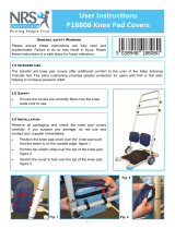
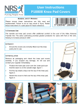
OVERVIEW MOBILE STANDING DEVICE
1. chest truss pad
2. side chest truss pad
3. belt for side chest truss pad
4. cushion for posterior truss
pad with swivel bracket and
crank
5. swivel bracket
6. side posterior truss pad
7. centre column
8. standard knee truss pads
9. sprung back caster
10. standard foot plate
11. drum brake nob
12. gas pressure spring
13. front caster
14. release pedal for gas
pressure spring
1. chest truss pad
2. therapy table
3. toy box
4. crank for posterior truss
pad with swivel bracket
5. side posterior truss pad
6. centre column
7. frame
8. drum brake nob
9. profile wheel
10. built in hand rim
11. side chest truss pad
12. belt for chest truss pad
13. star knob lock for the pelvic
truss pad with crank and
swivel bracket
14. swivel bracket
15. cushion for posterior truss
pad
16. axle plate
17. standard knee truss pads
18. standard foot plates
19. clamping device for the
height adjustment of the
back casters
20. locking lever for the back
casters
21. sprung back casters
1
2
3
4
5
6
7
8
9
9
10
1011121314
21
20
19
18
17
16
15
14
13
12
11

Boogie Drive
6
1 PREAMBLE
1.1 GENERAL INFORMATION
ONLY THE SETTING PROCESSES WHICH CAN BE CARIED
OUT WITHOUT TOOLS AS WELL AS PARTS WHICH
AFFECT THE DIRECT USE ARE STATED IN THIS USER
MANUAL. ALL WORK FOR THE BASIC SETTING AND
THE ADJUSTMENTS ARE DESCRIBED IN THE SERVICE
RECORD. IF NECESSARY RECEIVE THE INFORMATION
THERE.
This mobile standing device has been built, adjusted
and given to you operable according to your individual
instructions. A qualified Technician will make any changes
necessary, should modification be needed during use. As
any other aid, a mobile standing device is a technical device
that can hold risks if not properly used.
Please regard that you can find indications and graphics
here, which may differ to your mobile standing device
because of the individual equipment.
ATTENTION
Read the following instructions and manuals carefully :
READ
General use and safety instructions.
You can also find these online at
www.sorgrollstuhltechnik.de/downloade
ATTENTION
If the user of the wheelchair is a child or a person with
limited competence, the parents or authorized supervisor
have to make sure that they have fully understood the
handling of the mobile standing device as well as the
safety instructions before it is first used.
If you have any questions your medical supply store or our
competent team is glad to assist you (+49 7254-9279.0).
1.2 SIGNS AND SYMBOLS
ATTENTION
This is how individual-related safety aspects of utmost
importance are indicated.
� INDICATION
This is how possible indications of utmost importance are
labelled.
INFORMATION
This is how INFORMATION on mounting and adjustment
work is labelled.
READ
This refers to other chapters within the brochure or to
additional material.
BOLD PRINT
Text in bold print highlights important passages or remarks.
1.3 INDICATION
The maximum amount of time spent in the mobile standing
device depends on the disorder and is set by the users
doctor. These guidlines are to be kept.
Boogie Drive is indicated
• by all therapy forms for uprighting and controlled, careful
strain of all bones,
• to acitvate or to preserve/develop the whole muscle
tone or individual muscle groups,
• to stimulate/strengthen the sensitive integration
(perception) or vestibular stimulation,
• to develop/preserve the motor function differentiation,
• for prophylaxis of tone abnormalties (spastic
malpositions etc.),
• to stimulate/strengthen the complete metabolism,
the autonomic nervous system and the whole
cardiovascular system,
• by vegetative disruptions,
• to work against perception and/or communication
trouble.
1.4 COUNTER INDICATION
Also, it must be cleared with the doctor how far the user
can be put in a stretch position. In many cases it is (at first)
only possible to stand in a bent position.
During the therapeutic use, the following symptoms may
accur:
• circulation problems
• joint and/or muscle pain in legs and/or spine area
• spastic attacks.
THE USE MUST THEN BE STOPPED IMMEDIATELY.
Furthermore, Boogie Drive is counter indicated by:
• severe impaired perception and sense of balance,
• limb loss,
• joint contractures/joint damages on both arms and/or
legs,
• not enough eyesight for active driving
.
ATTENTION
Under the following circumstances and/or symptoms,
please consult your doctor or therapist prior to any
passive or active use of Boogie Drive:
• User whose skin is not intact,
• if the impairment of motor functions is grave.
� INDICATION
WE ARE NOT LIABLE FOR HEALTH-RELATED AND/OR
ANY OTHER KIND OF DAMAGE OF PEOPLE AND OBJECTS
OCCURRING UNDER THE ABOVE CIRCUMSTANCES WHEN
USING THE MOBILE STANDING DEVICE.

User Manual
7
1.5 SPECIFICATION BOOGIE DRIVE
Boogie Drive is a mobile standing device with a centre
column, which can be adjusted steplessly with a gas
pressure spring or set mechanically with a telescope 15°
forward.
(With frame size 1, the centre column can also be set in
length).
With the variable body guiding truss pads and the height
adjustable foot plate holder, an anotomical correct support
according to the three-point-method is achieved.
The body guiding truss pads are all adjustable in height,
depth and, if necessary, width.
The foot plate holder can be adjusted in height.
Each foot plate can be aligned in distance independantly
from one another, can be abducted seperately and
individually spread out (e.g. postoperative cast pants).
The tilting angle of the foot plates can also be set optionally
(talipes equinus), also independant from one another.
These 3 frame sizes are available:
The camber can be set to either 0°, 3°, 6°, 9° and 12°.
The shoulder-wheel-position is set to the user - see the
following list.
Size Frame
width
User mea-
surements
Possible
wheel sizes
Possible
camber
S. 1 36 cm
(+4 cm)
80-110
24“, 26“, 28“
3°, 6°,
9° 12°
S. 2
40 cm
(+4 cm)
100-130
28“, 30“,
32“
3°, 6°,
9° 12°
S. 3
44 cm
(+4 cm)
120-150
32“, 36“
0°, 3°,
6°, 9°
1.6 BASIC EQUIPMENT
• frame with angle adjustable centre column 0°-15°
(optional with gas pressure spring)
• profile wheels with built in hand rims, drum brake and
puncture proof tyres,
• adjustable camber,
• one or two casters in front,
• two sprung casters in back with locking lever
• height adjustable foot plate holder with foot plates,
individual, three dimensional adjustment
• knee truss pads, three dimensional adjustment
• pluggable posterior truss pad, height and depth
adjustable
• chest truss pad, height and angle adjustable
� INDICATION
According to the German Aid Index Number, Boogie Drive
must be equipped with heel edges and foot belts. The-
se are not included in the basic equipment. The profile
wheels are also not included in the base price.
1.7 BASICS TO ALL ADJUSTMENT WORK
ON THE MOBILE STANDING DEVICE
ATTENTION
BEFORE THE FIRST USE OF THE MOBILE STANDING
DEVICE THE CENTRE COLUMN, THE WHEELS, THE FOOT
PLATES, THE KNEE, POSTERIOR AND THE CHEST TRUSS
PADS MUST BE SET TO THE INDIVIDUAL MEASUREMENTS
OF THE USER. IT MUST BE CLOSE TO BEING READY FOR
USE.
IT IS NOT ADMISSIBLE TO MAKE ADJUSTMENTS WHEN
THE USER IS IN THE WHEELCHAIR! THEN, ONLY FINE
ADJUSTMENTS ARE ALLOWED TO BE MADE.
The mobile standing device is set to your individual
measusrements by your therapist or your rehab
technician before the first use.
Although it is still possible that afterwards fine
adjustments need to be made while you are standing in
the Boogie. Your therapist or rehab technician will be
very careful and will be assisted by a qualified assistant.
INFORMATION
If the mobile standing device is used in an area without
threshold, it is recommended to set the back casters so
that each wheel has contact with the ground.
If you need to overcome doorways or the like more
frequently, it is recommended to set the back casters so
that the front casters are not touching the ground.
These adjustments are made by the height adjustment of
the back casters (see service record).
1.8 APPLICATION
The intended use of the mobile standing device requires
thorough instruction of the assisting person or the user
in all adjustement possibilities and the associated safety
hazards.
ATTENTION
THE MOBILE STANDING DEVICE CAN ONLY BE USED
INDOORS ON A FLAT, FIRM SURFACE AND CAN ONLY BE
USED BY THE PERSON FOR WHOM IT WAS BUILT FOR
AND ADJUSTED TO.
ATTENTION
IT IS NOT SUITABLE FOR OUTDOORS.
ATTENTION
THE MAXIMUM LOAD CAPACITY IS NOT TO BE EXCEEDED.
ATTENTION
It is not allowed to be used as means of transportation
for goods, objects or the like.

Boogie Drive
8
ATTENTION
The user can never be left alone in the aid.
ATTENTION
The mobile standing device can not be used with faulty,
worn or missing parts.
ATTENTION
The mobile standing device can only be used when all as-
sembly parts have been correctly mounted on and adju-
sted.
ATTENTION
Because of fire safety reasons, the mobile standing
device cannot be placed next to an open flame or another
heat source such as electric or gas heater.
ATTENTION
Only original spare parts are to be used.
INFORMATION
Follow the care and maintenance plan
.
1.9 RECEPTION
DELIVERY
Each wheelchair/mobile standing device is mounted,
tested for functionality and correctness in our works and
packaged into special cardboard boxes by our shipping
experts.
FORWARDING COMPANY
For liability reasons we have to ask you to check the
wheelchair/mobile standing device immediately after
receiving it AND IN THE PRESENCE OF THE DELIVERER
(forwarding company) for possible damages that may have
occurred during transportation.
� INDICATION
DO NOT SIGN THE NOTICE OF RECEIPT FROM THE
FORWARDING COMPANY BEFORE THOROUGHLY
CHECKING THE WHEELCHAIR FOR DEFECTS.
� INDICATION
In case of damage state on the confirmation of reciept
that you have received the wheelchair with damgages.
TRANSPORTATION DAMAGES
In case of damage write a short record of the damage and
review of events, if possible include pictures clearly showing
the damage,
• get the personal information of the bearer (driver‘s
license etc., or the car number and the delivery
company),
• inform us immediately.
� INDICATION
ACCORDING TO THE VALID LAW, DAMAGES REPORTED
LATE CAN NEITHER BE ASSERTED TO US NOR TO THE
FORWARDING COMPANY!
1.10 DOCUMENTATION
� INDICATION
Keep this user manual in a safe place. Have all work/
repairs done on your wheelchair documented by the
medical supply store in the maintenance plan. If
applicable, hand it back to your benefactor along with
the wheelchair.
� INDICATION
In the event of the wheelchair/mobile standing device
being reused, it is an important source of information
for you benefactor. It provides evidence of regular
inspections which might be relevant in the event of
warranty claim.
ATTENTION
For safety reasons have all repairs done and documented
solely by a qualified specialized trade.
1.11 SERVICE AND MAINTENANCE
READ
According to § 33 subparagraph 1, clause 4, [German]
SGB V, the responsibility of maintenance, repairs and
replacement lies with the benefactor. After agreement
with your benefactor, be sure to have all safety relevant
inspections, maintenance work and if necessary repairs
conducted in order to make the wheelchair functional.
INFORMATION
Be careful with all moveable parts since there is a RISK
of crushing fingers and other body parts.
ACHTUNG
The regular inspection of all safety relevant parts on
the aid by a qualified rehab workshop is the only way to
prevent damages and maintain our liability.
INFORMATION
Proceed according to the maintenance plan in chapter 4 of
this user manual.

User Manual
9
2 SAFETY INSTRUCTIONS
2.1 GENERAL INDICATIONS
ATTENTION
BEFORE THE FIRST USE OF THE MOBILE STANDING DE-
VICE, THE CENTRE COLUMN, THE WHEELS, THE FOOT
PLATES, THE KNEE, POSTERIOR AND CHEST TRUSS PADS
MUST BE SET TO THE INDIVIDUAL MEASUREMENTS OF
THE USER. IT MUST BE CLOSE TO BEING READY FOR USE.
IT IS NOT ADMISSIBLE TO MAKE ADJUSTMENTS WHEN
THE USER IS IN THE WHEELCHAIR! THEN, ONLY FINE
ADJUSTMENTS ARE ALLOWED TO BE MADE.
ATTENTION
TO ADJUST THE ANGLE OF THE CENTRE COLUMN WITH
TELESCOPE AND CLAMP LEVER THE MOBILE STANDING
DEVICE MUST BE EMPTY.
ATTENTION
BEFORE EACH TIME THE USER GETS INTO THE MOBILE
STANDING DEVICE, IT MUST BE SECURED FROM ROLLINT
AWAY.
SECURE THE MOBILE STANDING DEVICE FROM ROLLING
AWAY BY CLOSING THE DRUM BRAKE AND THE WHEEL
LOCKS OF THE BACK CASTERS.
ATTENTION
STEPS AND STAIRS ARE NOT TO BE OVERCOME WITH
THE MOBILE STANDING DEVICE. JUST AS WELL, A PER-
SON CANNOT BE CARRIED UP STEPS OR STAIRS WHILE
IN THE MOBILE STANDING DEVICE.
ATTENTION
Injury risk on all rotating or turnable parts.
ATTENTION
The mobile standing device can only be used according
to its purpose. Any other use or misuse can contain se-
rious risks for you and your surroundings. Also, the gua-
rantee or product liability can be terminated in case of
misuse!
ATTENTION
All building alterations are not to be done without our
approval and must be carried out and documented by us
or a qualified rehab technician.
ATTENTION
Do not make repairs and/or do maintenance work your-
self. Contact your qualified rehab technician.
READ
Before operating the mobile standing device, read this user
manual attentively.
READ
Consider the indications for maintenance and inspection at
the end of the operating instructions.
2.2 DANGER OF TIPPING AND FLIP-
PING OVER
ATTENTION
The danger of tipping and flipping over can occur from all
forms of height differences (steps, doorways, stairs) as
well as leaning out to the side and/or back of the mobile
standing device.
The assistant and/or caretaker is responsible that the
patient is securely in the mobile standing device, is
strapped in where necessary and all lockable truss pads
are tightly locked.
ATTENTION
The most important supporting points according to the
three point method are: knee truss pads, posterior truss
pads and chest truss pads.
Before each use, check the firm and reliable fit of the
chest and knee truss pads and after getting in the firm
and reliable fit of the posterior truss pads.
ATTENTION
IN BOTH MODELS OF THE POSTERIOR TRUSS PAD, THE
STAR KNOB SCREW MUST BE TIGHTENED FIRMLY. THE
LATCH ALONE IS NOT ENOUGH FOR STABILIZING!
ATTENTION
If you operate the release latch of the gas pressure spring
on the centre column, the user can suddenly jerk forward
or backward and at the worst, hurt themselves.
THEREFOR, ONLY OPERATE THE REALEASE LATCH IN THE
PRESENCE OF AN ASSISTING PERSON WHO SUPPORTS
THE USER.
2.3 OTHER RISKS
� HINWEIS
Avoid direct sunrays. Dark parts on the mobile standing
device can heat quickly and can possibly cause burns.
ATTENTION
FIRE RISK of the textile parts (truss pad cushions and
covers). Keep sources of ignition away from the mobile
standing device.
ATTENTION
Do not use or place the mobile standing device in damp
rooms. Important parts my corrod, whereby the lifespan
of the aid is negatively influenced.
2.4 LOADING AND TRANSPORTING
ATTENTION
Stow and tie up all demounted/loose parts of the mobile
standing device securely in the vehicle so that if a sud-
den stop occurs, the parts will not harm anyone.
Secure the mobile standing device and all loose parts
with tension belts in the vehicle.

Boogie Drive
10
(2)
(B) (A)
(1)
(4)
(3)
(C)
(C)
(D)
(D)
(E)
(B)
(B)
(A)
(A)
3 HANDLING AND FINE ADJUST-
MENTS
3.1 ACTIVELY GETTING IN AND OUT
ATTENTION
WITH EVERY TRANSFRER IN/OUT OF THE MOBILE
STANDING DEVICE, AN EXPERIENCED CARER MUST BE
THERE TO ASSIST.
EACH TRANSFER CAN ONLY TAKE PLACE ON FIRM, EVEN
GROUNDS AND WITH ACTIVATED WHEEL LOCK WITH
THE MOBILE STANDING DEVICE AS WELL AS WITH THE
WHEELCHAIR.
DO NOT ONLY ACTIVATE THE DRUM BRAKES, BUT
ADDITIONALLY ALSO THE WHEEL LOCKS OF THE BACK
CASTERS ON THE MOBILE STANDING DEVICE.
3.1.1 Actively getting in with posterior truss
pad with additional standing support
ATTENTION
Getting in actively (independently) requires a lot of
strength and skill and for this reason can only be done
by experienced, strong users and only with the help of an
assisting person.
Getting in:
• (1) Drive with your wheelchair as close as possible
to the back of your mobile standing device.
• Secure it AND the mobile standing device from
rolling away (see above).
• Your carer loosens the star knob (A) and
• pulls the latch (B) to unlock down.
• At the same time, he/she pulls the complete truss
pad on the threaded rod (C) back out of the square
tube (D).
• (2) When your feet are placed in the foot plates (A)
and the belts
(B)
are closed securely,
• (3) grab hold of the centre column with both
hands and pull yourself as far up into a „standing“
position so that your knees are placed securely in
the knee truss pads.
Setting the depth of the posterior truss pad
• (4)
Your carer pushes the posterior tuss pad on
the threaded rod
(C) as far into the square tube
(D) until the wanted depth setting (= the wanted
standing pose)
is reached.
• (5)
With this, the latch (A) automatically relents and
snaps along the grid
(B)
.
• (4)
When the depth setting of the posterior truss
pad is finished,
• your carer will fixate the posterior truss pad by
turning the star knob
(A) until the wedge (E) has
stabilised the truss pad, free of play, in the square
tube (D).
• If available, have the belt of the side chest and/or
pelvic truss pad closed.
ATTENTION
VITAL FOR THE FIRM, SECURE AND RELIABLE FIT OF THE
POSTERIOR TRUSS PAD IS THE STAR KNOB (1A, 4A). FOR
THE SAFE USE OF THE BOOGIE IT IS REQUIRED THAT THE
STAR KNOB WAS TIGHTLY CLOSED! THE BOOGIE IS NOT
OPERABLE WITHOUT A FIRM FIT OF THE STAR KNOB
SCREW.
(5)
(B)
(A)

User Manual
11
3.1.2 Actively getting out with posterior truss
pad with additional standing support
ATTENTION
Secure the mobile standing device AND the wheelchair
(as already described) from rolling away.
• Put the centre column - if possible - in a verticle
position.
ATTENTION
WHEN PLACING THE CENTRE COLUMN WITH A GAS PRES-
SURE SPRING VERTICLY, BE SURE TO NOTE THAT WHEN
RELEASING THE WHOLE WEIGHT OF THE USER PUSHES
BACKWARD.
• Drive backwards as close as possible to the
front edge of your wheelchair seat or have the
wheelchair pushed to the back of the mobile
standing device.
• If necessary, have the belt of the pelvic truss pad
open.
• If possible, hold on to the centre column with both
hands.
• Have your carer open the posterior truss pad
(according to the previous chapter).
• Slowly (!) let yourself back onto the seat of your
wheelchair while being supported.
• When you are securely sitting in the wheelchair
your carer will then open the belts of the foot plates
(see chapter foot plates).
• Place your feet back on to the foot plate/s of your
wheelchair.
•
3.1.3 Actively getting in with posterior truss
pad with crank and swivel bracket
ATTENTION
REGARD ALL INSTRUCTIONS OF CHAPTERS 3.1 AND 3.1.1.
• Proceed as described in chapter 3.1.1 .
• (1) Your carer loosens the star knob (A),
• pulls the latch (B) to unlock down and
• swings the bar (C) all the way back.
• (2) When your feet are placed in the foot plates (A)
and the belts
(B)
are closed securely,
• grab hold of the centre column with both hands
and pull yourself as far up into a „standing“
position so that your knees are placed securely in
the knee truss pads.
• (3)
Your carer closes the bar (A).
• The latch (B) must snap into place.
• Then he/she will tighten the star knob
screw (C).
Setting the depth of the posterior truss pad
• (4)
At the end, your carer will set the necessary
depth of the posterior truss pads and places you in
the wanted standing pose, by turning the crank
(A)
• If available, close the belt of the side chest truss
pads.
ATTENTION
T
HE STAR KNOB SCREW MUST BE SCREWED ON TIGHTLY
IN BOTH VERSIONS OF THE POSTERIOR TRUSS PADS.
THE LATCH ALONE IS NOT ENOUGH FOR STABILISATION!
THE BOOGIE DRIVE IS NOT OPERABLE WITHOUT A FIRM
FIT OF THE STAR KNOB SCREWS
.
(1)
(4)
(3)
(A)
(B)
(A)
(C)
(B)(C) (A)
(2)
(B)(A)

Boogie Drive
12
3.1.4 Actively getting out with posterior truss
pad with crank and swivel bracket
ATTENTION
Secure the mobile standing device AND the wheelchair
(as already described) from rolling away.
• Put the centre column - if possible - in a verticle
position.
ATTENTION
WHEN PLACING THE CENTRE COLUMN WITH A GAS PRES-
SURE SPRING VERTICLY, BE SURE TO NOTE THAT WHEN
RELEASING THE WHOLE WEIGHT OF THE USER PUSHES
BACKWARD.
• Drive backwards as close as possible to the
front edge of your wheelchair seat or have the
wheelchair pushed to the back of the mobile
standing device.
• If necessary, have the belt of the pelvic truss pad
open.
• If possible, hold on to the centre column with both
hands.
• Have your carer open the posterior truss pad
(according to the previous chapter).
• Slowly (!) let yourself back onto the seat of your
wheelchair while being supported.
• When you are securely sitting in the wheelchair
your carer will then open the belts of the foot
plates (see chapter foot plates).
• Place your feet back on to the foot plate/s of your
wheelchair.
3.2 POSITIONING THE USER IN THE
MOBILE STANDING DEVICE
ATTENTION
EACH TRANSFER IN/OUT OF THE MOBILE STANDING
DEVICE MUST BE CARRIED OUT BY AN EXPERIENCED
CARER.
EACH TRANSFER CAN ONLY TAKE PLACE ON FIRM, EVEN
GROUNDS AND WITH ACTIVATED WHEEL LOCK WITH
THE MOBILE STANDING DEVICE AS WELL AS WITH THE
WHEELCHAIR.
DO NOT ONLY ACTIVATE THE DRUM BRAKES, BUT
ADDITIONALLY ALSO THE WHEEL LOCKS OF THE BACK
CASTERS ON THE MOBILE STANDING DEVICE.
Getting in
• Secure the mobile standing device AND the
wheelchair from rolling away (see previous
chapter).
• (1) To remove the posterior truss pad your carer
opens the star knob (A),
• pulls the latch (B) down
• and the threaded rod (D) out of the guide tube, at
the same time.
• (2) With a circular posterior truss pad with crank,
your carer turns the star knob (C) open as far as
needed, pulls the latch (B) down
• and swings the tube (A) back.
• Your carer brings you as close as possible, from
behind, to the mobile standing device.
• When your feet are securely in the foot shells and
are belted,
• your carer will pull you by the arms and/or push
you from behind at the bottom/pelvis into the
mobile standing device.
Setting the depth of the posterior truss pad
• (1) Your carer puts the posterior truss pad in the
square tube (D), until the latch
(B) snaps into the
rows of holes (C) and
• pushes the truss pad as far into the square tube
(D) until the wanted elongation is reached.
• (2) With the posterior truss pad with crank and
swivel bracket, he/she should proceed as stated in
the previous chapters.
ATTENTION
(1+2) THE STAR KNOB SCREW (1A/2C) MUST BE
SCREWED ON TIGHTLY IN BOTH VERSIONS OF THE
POSTERIOR TRUSS PADS. THE LATCH (B) ALONE IS NOT
ENOUGH FOR STABILISATION! THE MOBILE STANDING
DEVICE IS NOT OPERABLE WITHOUT A FIRM FIT OF THE
STAR KNOB SCREWS (1A/2C).
• After, your carer will secure you with the belt on the
chest truss pad or on the side pelvic truss pads.
• If necessary, your carer will put the headrest in the
wanted position and tilt the centre column.
INFORMATION
The fine adjustment work is explained in the service record.
ATTENTION
WHEN TILTING THE CENTRE COLUMN, ALL WHEEL LOCKS
MUST BE LOCKED.
THE MECHANICAL TILTING ADJUSTMENT OF THE CENTRE
COLUMN MAY ONLY OCCUR WHEN THE AID IS EMPTY.
(2)
(A)
(B)
(C)
(1)
(C)
(D)
(B)
(A)

User Manual
13
3.3
CENTRE COLUMN
Setting the angle of the centre column
ATTENTION
THE ANGLE SETTING OF THE CENTRE COLUM WITH
TELESCOPE AND CLAMP LEVER CAN ONLY BE CARRIED
OUT WHEN A PATIENT IS IN THE AID.
Adjusting the angle of the centre column
ATTENTION
(3) IN ORDER TO ADJUST THE CENTRE COLUMN YOU
MUST HOLD THE PATIEND AND/OR THE CENTRE CO-
LUMN WITH BOTH HANDS WHILE YOU ACTIVATE THE RE-
LEASE LEVER (A).
ATTENTION
THE ANGLE ADJUSTMENT OF THE CENTRE COLUMN
WITH GAS PRESSURE SPRING CAN ONLY OCCUR WHILE
STANDING STILL AND WITH ACTIVATED WHEEL LOCK
(DRUM BRAKE AND BACK CASTERS).
• Press the release lever of the gas pressure spring
down with your foot,
• place the centre column in the desired angle and
• let go of the release lever (A).
(A)
(2)
3.4 FOOT STRAPS
To close the foot straps:
• (2) The clasp (A) of the fastener (B) must be open
(see picture).
• (3)
Guide the strap
(C) from the front in the fastener
(B)
, without tightening it too much. When closing the
clasp
(A)
the strap
(C)
tightens.
• Push the strap
(C)
as far as needed in the fastener
(B)
and
• (4) close the clasp (A).
To tense the foot straps:
• Put the clasp (A) out of the half open position
(picture 2) in the closed position (picture 3)
• repeat the process until the user‘s foot is tightly
enclosed by the strap
To open the foot straps:
• (4) Open the clasp (A) all the way (see picture 2)
and
• pull the strap (C) all the way out of the fastener (B).
(A)
(A)
(A)
(B)
(B)
(B)
(C)
(C)
(C)
(C)
(2)
foot straps open
foot straps half open/closed
foot straps closed
(3)
(4)

Boogie Drive
14
(1)
3.5 BACK TRUSS PADS
(1) Height adjustment of the back truss pad:
• Open the clamp lever (A) of the posterior truss
pads so far that you can push the beam (B) of the
back truss pad in the holder (C) freely up or down.
• Place the beam (B) in the wanted height.
• Turn the clamp lever (A) through one of the
alternative holes (D) and
• retighten the clamp lever (A).
Adjusting the depth and angle of the back truss pads:
• Loosen the set screw (E),
• push the headrest in the wanted position and
• retighten the set screw (E).
• To adjust the angle loosen the screw (F),
• place the cushion in the wanted tilt
• and retighten the screw (F).
3.6 CHEST TRUSS PAD
3.6.1 Height adjustment of the chest truss
pads
ATTENTION
The necessary work is described in the service book and
can only be done by a qualified rehab technician.
3.6.2 Tilt angle of the chest truss pad
To adjust the tilt angle of the chest truss pad:
• (1) Loosen the clamp lever (A)
• turn the holder (B) of the chest truss pad in the
wanted tilt and
• retighten the clamp lever (A).
3.7
SIDE CHEST TRUSS PADS
(3) To adjust the width of the side chest truss pads:
• (2) Remove both set screws (A)
• extend the holder (B) to the wanted distance
• replace and retighten the set screws (A).
(3) To adjust the depth of the side chest truss pads:
• (2) Remove on both sides both setscrews (C)
• place the cushions (B) in the desired distance
• and replace and retighten the setscrews (C).
(A)
(C)
(B)
(E)
(F)
(D)
(2)
(A) (B)
(3)
(A)
(C)
(B)

User Manual
15
(A)
(B)
(1)
(2)
(3)
3.8 PELVIC TRUSS PADS
INFORMATION
Die Pelotten können wahlweise mit Stellschrauben oder
Klemmhebel ausgestattet sein.
Im Folgenden wird der Einstellvorgang anhand des je-
weils benutzten Bildes beschrieben. Sollte Ihr Stehfahrer
anders ausgestattet sein, verfahren Sie bitte sinngemäß.
3.8.1 Height adjustment
(1) To adjust the height:
• Open the clamp lever (A),
• move the holder (B) along the centre column (C) to
the desired position
• and retighten the clamp lever (A).
3.8.2 Width adjustment
(2) To adjust the width:
• Open the clamp levers (A),
• telescope both bails (B) to the desired measure-
ment
• and retighten both clamp levers (A).
3.8.3 Depth adjustment
(3) To adjust the depth
• Open the clamp levers (A) on both sides,
• displace both truss pads (B) to the desired position
• and retighten both clamp lever (A).
(A)
(A)
(B)
(B)
(C)

Boogie Drive
16
3.9 STANDARD KNEE TRUSS PADS
ATTENTION
THE KNEE TRUSS PADS MUST HAVE BEEN SET TO
THE INDIVIDUAL MEASUREMENTS OF THE CHILD/
ADOLESCENT AS EXACT AS POSSIBLE BEFORE THE FIRST
USE OF THE MOBILE STANDING DEVICE.
WHEN THE USER
IS STANDING IN THE MOBILE STANDING DEVICE, ONLY
FINE ADJUSTMENTS ARE THEN ALLOWED TO BE MADE.
INFORMATION
We recommend BEFORE the first use, to set the width of
the knee truss pads to the measurements of the user. For
this, please remove the knee truss pads.
3.9.1 Adjusting the truss pad width size 1
(1) To adjust the knee truss pad:
• Loosen both screws (A),
• telescope both holders (B) along the elongated
hole to the desired measurement
• and retighten both screws (A).
3.9.2 Adjusting the truss pad width size 2
(2) To adjust the knee truss pad:
• Loosen all four screws (A),
• telescope both holders (B) to the desired
measusrements
• and retighten all screws (A).
3.9.3 Adjusting the height
(3) To adjust the height:
• Loosen the screw (A),
• displace the holder (B) to the desired height and
• retighten the screws (A).
(3) And/or:
• Loosen the screws (D) on both sides,
• turn the holders (C) 180° and
• retighten the screws (D).
(3) And/or:
• Loosen the screws (D) on both sides,
• remove the holder (C),
• turn the holder (C) vertical 180°,
• place it back on the holder (B) and
• retighten the screws (D).
3.9.4 Adjusting the depth
(3) To adjust the depth:
• Loosen the screws (D) on both sides,
• move the pillars (C) of the knee truss pads, on both
sides, to the desired position
• and retighten the screws (D).
3.9.5 Adjusting the distance
(3) To adjust the depth:
• Loosen the screws (D) on both sides,
• move the holders (E) of the knee truss pads, on
both sides, to the desired position
• and retighten the screws (D).
(1)
(A)
(B)
(2)
(A)
(B)
(3)
(A)
(B)
(C)
(D)
(E)

User Manual
17
3.10 KNEE TRUSS PADS WITH RESTING
BRACKETS
ATTENTION
THE KNEE TRUSS PAD MUST HAVE BEEN SET TO
THE INDIVIDUAL MEASUREMENTS OF THE CHILD/
ADOLESCENT AS EXACT AS POSSIBLE BEFORE THE FIRST
USE OF THE MOBILE STANDING DEVICE.
WHEN THE USER
IS STANDING IN THE MOBILE STANDING DEVICE, ONLY
FINE ADJUSTMENTS ARE THEN ALLOWED TO BE MADE.
INFORMATION
We recommend BEFORE the first use, to set the width
and the shear angle of the resting brackets to the mea-
surements of the user. For this, please remove the knee
truss pads
3.10.1 Adjusting the truss pad width
(1) The brackets (A) of the knee truss pads can be bent.
• Press the brackets (A) on both nuts (B) apart or
togther to the desired measurement.
• After, test the fitting of the knee truss pads on the
user.
ATTENTION
INJURY RISK
ONLY PRESS THE BRACKETS TOGETHER WHEN THE TRUSS
PAD IS „EMPTY“. VICE VERSA, YOU CANNOT FORCE THE
KNEE OF THE USER IN A TOO TIGHT TRUSS PAD IN ORDER
TO WIDEN IT.
3.10.2 Adjusting the shear angle
(1) To change the shear angle:
• Loosen both nuts (B) of the truss pad on the inner
and outer side,
• place the brackers (A) in the desired angle
• and retighten all nuts (B).
• Test the fitting of the knee truss pads on the user.
• After, mount the knee truss pads back on to the
Boogie.
3.10.3 Adjusting the height
(2) To adjust the height:
• Loosen the clamp lever (A),
• displace the whole pillar of the knee truss pads (B)
to the desired position and
• retighten the clamp lever (A).
.310.4 Adjusting the depth
(3) To adjust the depth:
• Loosen the clamp lever (A),
• displace the whole pillar of the knee truss pads (B)
to the desired position and
• retighten the clamp lever (A).
3.10.5 Adjusting the distance
(4) To adjust the distance:
• Loosen the clamp lever (A),
• displace the holder (C) of the knee truss pads in
the desired position and
• retighten the clamp lever (A).
(1)
(2)
(3)
(4)
(B)
(A)
(B)
(A)
(A)
(B)
(B)
(A)
(C) (C)

Boogie Drive
18
(1)
(B)(A)
(C)
(2)
(A)
(B)
(C)
(3)
(B)
(D)
(E)
(4)
(A)
3.11
WHEEL LOCK
3.11.1
Drum brake
Normally the control lever of the drum brake is attached to
the therapy table.
To lock/unlock the drum brake:
• (1+2) Depending on the position of the control lever, in
order to lock the drum brake, pull the brake lever (A)
up so far until the small locking lever (B) snaps into the
groove (C).
• The drum brakes are now blocked.
• (1+2) To loosen the blockage pull the brake lever (A)
a little further up, so that the small locking lever (B)
unlocks out of the groove (C).
• Then release the brake lever (A).
• The drum brakes are now deactivated.
ATTENTION
To secure the mobile standing device always use, in
addition, the locking levers of the back casters (regard the
corresponding chapter).
3.11.2
Displacing the brake control lever
To displace the lever:
• (3) Loosen the clamp lever (A) by lifting up,
• pull the whole control lever (B) back, out of the holder
(C),
• (2) place the control lever (B) in the alternative holder
(D) on the centre column and
• tighten this clamp lever (E).
• The height adjustment of the holder on the centre
column is described in the service record.
3.11.3
Back casters with locking lever
To lock/loosen the back casters:
• (4) Push the locking lever (A) with your foot back and
down.
• To release the brake push the upward sticking pedal (A)
back into its original position.
ATTENTION
SECURING THE MOBILE STANDING DEVICE SOLELY WITH
THE BRAKES OF THE BACK CASTERS IS NOT ENOUGH! IN
ADDITION ALWAYS USE THE DRUM BRAKES.

User Manual
19
(A)
(B)
(3)
(A)
(1)
(2)
(4)
3.12 WHEELS
3.12.1 Driving wheels
• (1+2) To loosen or apply the quick release axle push
the locking knob (A) in the middle of the hub and
release it after.
• (3) After application, the locking ball (A) should stick
out visualy at the end of the quick release axle fitting
(B). The wheels should not be removable anymore.
ATTENTION
(3) When putting on the driving wheels always be sure
that the locking ball (A) of the quick release axle is
visually sticking out on the inside of the quick release
axle fitting (B).
Varify the functionality of the small locking ball (A) at the
end of the quick release axle regularly.
Wheels are turning parts and can hurt your fingers.
3.12.2 Casters in front and back
The mobile standing device is constructed in a way so
that when the centre column is in a verticle position, no
weight is on the front caster/s but all of it on the back
ones.
INFORMATION
The back casters are sprung in order to absorb impacts
(e.g. when bobbing). Should a modification of the
back caster height be necessary, because of possible
obstacles in your surroundings, the distance between
ground and back casters can be set.
Please contact your rehab technician for necessary
adjustment work.
3.13
OVERCOMING OBSTACLES
With surroundings that are not barrier free, the aid must
be modified so that the back casters float over the ground
when unloaded. This way the aid can be easily tilted back
on to the sprung casters in order to bring the front casters
easily over the obstacle.
ATTENTION
(4) NEVER OVERCOME STAIRS ETC. WITH THE MOBILE
STANDING DEVICE
ATTENTION: DANGER OF FLIPPING OVER
Cross over the threshold only at right angle - never
slanted.
In order to drive over a threshold:
• Drive slowly and at a right angle until you have
almost reached the threshold,
• shift your weight back
• and bring the front, now floating caster/s over the
obstacle.
• Shift your weight back to the front and
• drive over the obstacle.

Boogie Drive
20
3.14 THERAPY TABLE
The therapy table is attached to the centre column ex works
(standard assembly). However, it can be varied in height
and also attached to the chest truss pad holder.
3.14.1 Standard mounting on the centre column
(1) To adjust the height:
• Loosen the star screw (A),
• move the therapy table on the holder (B) along the
centre column
• and retighten the star screw (A).
(1) To adjust the distance:
• Loosen the set screws (C),
• place the therapy table on the holder (D) in the
desired position and
• retighten the set screws (A).
(1) To adjust the tilt angle:
• Loosen the clamp lever (E),
• place the therapy table in the wanted tilt and
• retighten the clamp lever (E).
3.14.2 Mounting on the chest truss pad holder
(2) To adjust the height:
• Loosen the set screw (A),
• move the therapy table on the holder (B) along the
chest truss pad holder and
• retighten the set screw (A).
(2) To adjust the distance:
• Loosen the set screw (C),
• place the therapy table in the wanted distance and
• retighten the set screw (C).
(2) To adjust the tilt angle:
• Loosen the clamp lever (D),
• place the therapy table in the wanted tilt
• retighten the clamp lever (D).
(1)
(2)
(B)
(A)
(C)
(B)(A) (C)(D)
(E)
(D)
/