Page is loading ...

Corona Discharge Ozone Generators
INSTALLATION & OPERATION MANUAL
P/N: 4-1397-01 Rev.F

Table of Contents
CoPilot Corona Discharge Ozone Generators
SECTION 1
General Information
1A Dimensions ..............................................................1
1B Description ...............................................................2
1C Specifi cations ...........................................................2
1D Warranty Summary ..................................................2
SECTION 2
Installation
2A Location ...................................................................2
2B Mounting ..................................................................2
2C Electrical ..................................................................2
2D Plumbing ..................................................................2
SECTION 3
Operation
3A General ....................................................................3
3B Initial System Start-Up .............................................3
3C Normal Operation .....................................................3
3D Flow Control Assembly ............................................3
3E System Shut-down ...................................................3
SECTION 4
Maintenance & Service
4A System Electromechanical Overview .......................4
4B System Maintenance ...............................................4
4C Generator Servicing .................................................4
4D Troubleshooting ........................................................5
4E Contact Information ..................................................5
SECTION 5
Replacement Parts and Ordering
Information
5A Standard Replacement Parts List ............................6
IMPORTANT SAFETY INSTRUCTIONS
Read and Follow All Instructions
• Read this manual completely before attempting installation. Failure to install in accordance with the installation instructions
could void warranty and result in injury or death.
• All permanent electrical connections should be made by a qualifi ed electrician.
• For cord and plug-connected units, connect to a grounded, grounding type receptacle only. If the CoPilot electrical connection is to
be attached to the pool controls, be sure the pool controls are protected by a Ground Fault Circuit Interrupter (G.F.C.I.). If the CoPilot
is connected to an independent electrical supply, then a G.F.C.I. must be installed between the CoPilot and the electrical supply.
• Do not bury cord.
• Warning - To reduce the risk of electrical shock, replace damaged cord immediately.
• A pressure wire connector bonding lug is provided on the outside of the unit to permit connection to a minimum No. 8 AWG (8.4
mm
2
) solid bonding conductor between this point and any metal equipment, metal enclosures of electrical equipment, metal
water pipes, or conduit within fi ve (5) feet (1.5m) of the unit as needed to comply with local requirements.
• Install at least 5 feet (1.5 meters) from wall of pool using nonmetallic tubing. Install ozone generator no less than one (1) foot
above maximum water level to prevent water from contacting electrical equipment. Install in accordance with the installation
instructions.
• Follow all applicable electrical codes.
• Electric shock hazard. Be sure to turn power OFF and disconnect from power source before any service work is performed.
Failure to do so could result in serious injury or death.
• The CoPilot must be installed in an outdoor location, or indoors in a forced air ventilated room, and installed so that the orienta-
tion is exactly as shown in Figure 1. Install to provide water drainage of generator to protect electrical components.
• Mount the CoPilot so that it is inaccessible to anyone in the pool. Never attempt any servicing while unit is wet.
• Plastic ozone supply tubing is supplied with the CoPilot. Never replace this tubing with metal tubing.
• Warning - Short-term inhalation of high concentrations of ozone and long term inhalation of low concentrations of ozone can
cause serious harmful physiological effects. DO NOT inhale ozone gas produced by this device.
• For your safety, do not store or use gasoline, chemicals or other fl ammable liquids or vapors near this or any other appliance.
• WARNING - Do NOT touch the ends of the Ozone Check Valve and Tube Assembly or check valve when replacing. Trace amounts of
nitric acid may be present on the check valve and could prove harmful if touched or ingested.
SAVE THESE INSTRUCTIONS!
C

SECTION 1
General Information
General Information
1A Dimensions.
(All dimensions are in inches [millimeters])
2.9
74
2.6
67
2.9
74
COP-2-B: 1/2 THREADED CONDUIT
COP-B-CE: OPEN 18-3 CORD, 44IN LONG
9.3
235
219
8.6
382
15.0
13.6
344
COP-1-A: NEMA 5-15P, 44IN LONG
COP-2-A: 1/2 THREADED CONDUIT
COP-A-CE: OPEN 18-3 CORD 44IN LONG
10.3
262
219
8.6
235
9.3
8.6
217
CoPilot Corona Discharge Ozone Generators
1
Models: COP-1-A, COP-2-A, & COP-A-CE
Models: COP-2-B & COP-B-CE

2
™
rona Discharge Ozone Generator
| [email protected] | www.delozone.com
Generating Ozone Service Required
4-0738-01 Rev. B
TM
1C Specifi cations
Power Requirements:
COP-1-A . . . . . . . . 120V, 60 Hz, 1Ø, 0.06 Amp
COP-2-A . . . . . . . . 220V, 60 Hz, 1Ø, 0.03 Amp
COP-A-CE . . . . . . 230V, 50 Hz, 1Ø, 0.03 Amp
COP-2-B . . . . . . . 220V, 60 Hz, 1Ø, 0.06 Amp
COP-B-CE . . . . . . . 230V, 50 Hz, 1Ø, 0.06 Amp
Shipping Weight:
COP-A: Approx. 3.5 pounds / 1.6 kg
COP-B: Approx. 5.5 pounds / 2.5 kg
Location Requirements:
Mounting: Wall mount in a clean, protected area.
Ambient Temp: 30°F - 120°F (0°C - 50°C)
1D Warranty Summary
Limited Warranty:
See the Warranty Card Supplied with Manifold
Assembly .
Warning: Failure to perform annual replacement of
the Ozone Check Valve and Tubing Assembly may void
the second year of your warranty.
Accessory Kit Contents:
Installation and Operation Manual ....................1 ea
Hose Clamps ....................................................3 ea
Leak Test Cap ...................................................1 ea
Tube Adapter ...................................................1 ea
Flowmeter .........................................................1 ea
Flow Control Assembly .....................................1 ea
Check Valve and Tubing Assembly ...................1 ea
2
SECTION 1
General Information
General Information
1B Description
The CoPilot Corona Discharge (CD) series ozone gen-
erators described in this manual are designed to add the
benefi ts of ozonated water to your AutoPilot system in an
environmentally safe and effective manner. The high quality,
specially engineered components ensure effi cient ozone
output and reliable performance.
As a result of proper use of the CoPilot CD ozone genera-
tors, unpleasant effects of traditional chemical use are virtu-
ally eliminated. The CoPilot CD ozone generators are safe
and harmless to your equipment when installed properly.
SECTION 2
Installation
Installation
2A Location
The CoPilot units are designed for wall mounting. See
Figure 1. Mount generator in a clean, protected area, either
indoors or outdoors (preferably out of direct sunlight). Locate
generator out of reach of sprinklers or drainage spouts. Allow
suffi cient access for maintenance and all tubing and electrical
wires. The ozone generator should be installed at least (not less
than) one foot above the maximum water level.
2B Wall Mounting
1. Refer to Figure 1 to mark the locations for the four mounting
screws.
2. Install screws (or other hardware appropriate for the mount-
ing surface) through the two mounting slots built in to the
bottom end cap on the CoPilot. Install two more screws in
the fl anges towards the top.
2C Electrical
2C-1
. Main Power: The CoPilot must operate simultane-
ously with the pool pump. It may be wired directly to the pool
timing circuit or wired into the Pool Pilot Controller.
CAUTION: Risk of Electric Shock
Refer to the IMPORTANT SAFETY INSTRUCTIONS at the
beginning of this manual for important wiring information
2C-2. Bonding Lug: Using an 8AWG conductor, connect
the bonding lug on the right side of the CoPilot to an appropri-
ate earth contact.
2D Plumbing
Ozone gas is introduced to the pool circulation line using the
venturi injector installed in the AutoPilot Combination Bypass
Manifold. Water passing through the injector creates a suction
that pulls the ozone gas into the water. Water should never
travel back into the CoPilot Ozone Generator.
2D-1 Plumbing the Manifold: The AutoPilot Combination
Manifold is typically installed after all other pool equipment.
Follow the instructions in your Pool Pilot Controller Manual and
AutoPilot Cell/Manifold Assembly – Installation Instructions.
CoPilot Corona Discharge Ozone Generators
Figure 1 Wall Mount

2D-2 Special considerations for the AutoPilot Combina-
tion Manifold
Under normal operation, a small amount of gas is introduced
into the pool system by the injector. Plumb the Manifold so that
these bubbles do not interfere with the operation of pool equip-
ment. For example:
1. Install the manifold after any Pressure Pool Cleaners (such
as a Polaris 360).
2. Install the manifold after any Tablet/Erosion Feeders that
could collect gas bubbles.
2D-3. Water Check Valve: If the pool equipment is mounted
above the water line, a check valve must be installed between
the pump outlet and the Injector Manifold. This will prevent the
pump from draining and losing its prime (when not in use).
2D-4. Pressure Test:
If a pressure test is required, it should be performed prior to
connecting the Ozone Gas Line. A 3/4” pipe cap is provided
for the pressure test.
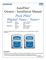
2D-5. Ozone Gas Line - refer to Figure 2.
1. Install Tube Adapter on injector. Use thread sealant if
needed. (Do not use thread tape.)
2. Connect the shorter end of the Ozone Check Valve and
Tube Assembly with the check valve installed onto the
Tube Adapter.
3. Cut off the excess tubing from the longer end so that the
line from the injector to the CoPilot is as straight and free
from dips and loops as possible.
4. Install Clamps on the Tube Adaptor and on both ends of
Check Valve.
Equipment
Ozone Check Valve
From Pool
Flowmeter
Tube Adapter
and Tube Assembly
to Pool
Return
Lug(s)
Bonding
Indicators
Ozone Power
Flow Control Assembly
(Install after checking flow)
(Preinstalled)
Check Valve
Clamps
3
Figure 2 Installation Diagram
5. The base of the CoPilot has two tube connections. Con-
nect the longer end of the ozone supply tubing to the
port marked "OZONE" (see Bottom View - Figure 3).
NOTE: Connecting the Ozone Line to the incorrect port
will cause damage to the ozone generator.
SECTION 3
Operation
Operation
3A General
To achieve optimal performance from the CoPilot system, the
pool must be as clean as possible to start with. Refer to the
“Pool Water Preparation” section of your Pool Pilot manual.
3B Initial System Start-Up
Upon completing all of the system connections and cleaning
the pool, you are ready to start the CoPilot.
1. Check electrical connections.
2. Check for proper voltage.
3. Turn on pool circulation system.
3C Normal Operation
1. Ozone Power Indicator Lights: When the pool’s circulation
system starts, the green LED indicator(s) on the front of
the CoPilot will illuminate. The COP-A and COP-B should
show 1 and 2 indicators, respectively.
2. Gas Flow: Connect the Flowmeter provided to the “AIR IN”
port on the base of the CoPilot (see Figure 3). Under worst-
case system conditions the Flowmeter Ball should indicate
at least a small amount of air fl ow. If not, adjust system
valves as required to reduce back pressure and/or increase
fl ow through the manifold. Under nominal conditions, the
Ball should fl oat above the middle of the fl owmeter. It is ok
if the Ball is all the way at the top if it is not stuck. Tap the
Flowmeter to verify that the Ball is not stuck.
If you experience complications see TROUBLESHOOTING
Section 4D.
3D Flow Control Assembly
Once proper suction is established, remove the Flowmeter
and install the Flow Control Assembly on the “AIR IN” port of
the CoPilot. The Flow Control Assembly must remain attached
to the CoPilot, except when temporarily removed to verify fl ow
with the Flowmeter
3E System Shut-Down
The following sequence of steps must be followed for servicing
or for storage.
CoPilot Corona Discharge Ozone Generators
Figure 3 CoPilot Connections

1. Disconnect the power to the ozone generator.
2. After the ozone generator has been shut down, the pool
water circulation pump may be turned off.
3. If the system is to be shut down for an extended
period, disconnect the Ozone Gas Line from the ozone
generator.
SECTION 4
Maintenance and Service
Maintenance and Service
4A System Electromechanical Overview
Refer to Figure 4.
4A-1 Ozone Module: The CoPilot Ozone Generators are con-
structed with High Voltage Corona Discharge Ozone Modules.
The COP-A has one Module, the COP-B has 2 modules.
4A-2. Indicator Lights: Each indicator light on the base of the
CoPilot corresponds to an Ozone Module inside the unit. Model
COP-A has one indicator, model COP-B has two. A green light
indicates proper operation of its respective Ozone Module. For
red indicators or no indicators, see Troubleshooting Section.
4A-3. Fuse: The CoPilot is equipped with an externally acces-
sible AGC-1 fuse, located on the base of the unit.
4B System Maintenance
4B-1. The green "ozone power” indicator light(s) on the front
of the CoPilot indicate that the ozone power supply is operating
properly. When an indicator light turns red, replace the corre-
sponding ozone module.
4B-2. Each ozone module should be replaced after 15,000
hours of operation. Even if the green indicator light(s) are glow-
ing, the ozone module may be producing little or no ozone
after this period of time due to contamination within the corona
discharge ozone chamber.
4B-3. Regularly reinstall and check the fl owmeter for proper
fl ow. Always remove the fl owmeter after confi rming proper
fl ow. Inspect ozone supply tubing for cracks or wear and
replace as necessary.
4B-4. Replace the Ozone Check Valve and Tube Assembly
every year or sooner, if needed. If there is evidence of water
leaking past the Check Valve toward the CoPilot shut down the
Ozone Generator Immediately and replace the Ozone Check
Valve and Tubing Assembly. If water entered the CoPilot allow
the unit to dry completely before restarting the unit. Evidence
of water in the CoPilot may void the warranty.
WARNING: Do NOT touch the ends of the Ozone Check Valve
and Tube Assembly or check valve when replacing. Trace
amounts of nitric acid may be present on the check valve and
could prove harmful if touched or ingested.
4B-5. While operating, check to see if bubbles are entering
the pool. If MDV is installed, check the MDV for bubbles.
4B-6. Clean or replace the Flow Control Assembly every
year or sooner if needed.
4C Generator Servicing - Refer to Figure 4
4C-1. Removing the Cover: The CoPilot ozone generator
may be serviced on the wall without disconnecting any of the
plumbing or wiring. Simply remove the cover as follows:
1. Shut down the pool system power, then disconnect power
to the ozone generator.
2. From the Top End-cap of the CoPilot, remove the 2 rear
screws.
3. From the Bottom End-cap, remove the 2 front screws. See
Figure 4 - Do not remove the screws securing the unit to
the wall.
4. Carefully lift and pull the cover off of the CoPilot.
5. Hold the cover and locate the screw connecting the ground
wire to the base. Remove the screw and set the cover
aside. Do not hang the cover from the ground wire.
6. The Base will remain fi rmly mounted to the wall with the
Ozone Modules fully accessible for servicing.
4C-2. Ozone Module Replacement
The green indicator lights on the front of the CoPilot corre-
spond from left to right to Ozone Module numbers 1 and 2.
The ozone modules are numbered beginning with number 1
at the bottom.
To replace an ozone module:
1. Open the CoPilot as described in section 4C-1.
2. Disconnect the tubing at both the inlet and outlet of the
ozone electrode.
3. Remove the two nuts that secure the ozone electrode to
CoPilot Corona Discharge Ozone Generators
4
Top View
Top Endcap-
Remove back
screws only
Remove
Cover
Bottom View
Bottom Endcap-
Remove front
screws only
Ozone
Power Supply
Module #1
Module #2
Ozone
Fuseholder
Electrode
Support Nut
Indicators
Electrode
Support Bracket
(Do not remove)
Figure 4 Component Locations (COP-2-B Shown).

the support bracket.
4. Disconnect the plastic power connector between the power
supply and wire harness.
5. Remove the two screws that secure the power supply to
the metal base.
6. Install the new ozone module by reversing the above steps.
4D. Troubleshooting
Knowledge of electrical applications is required for troubleshooting.
Contact a certifi ed electrician if you are unsure of your ability to
service the equipment. Improper servicing will void generator
warranty.
4D-1
Symptom: “LED Indicator” not lit when pool system
is on.
1. No power to the ozone generator from the power
source:
a. Check circuit breaker at the power distribution box.
b. Check for loose connections or wiring breaks from
the power distribution box to the generator.
c. Fuse in the unit has blown and needs to be replaced.
Fuse is an AGC-1 (1/4” x 1.25”long glass fuse).
2. G.F.C.I. has tripped.
a. Check power cord and reset G.F.C.I.
4D-2 Symptom: LED Indicator has turned red.
a. This means that the power supply of that specifi c
ozone module is no longer drawing power and needs
to be replaced. Refer to section 4C for instructions on
how to replace the corresponding ozone module.
Note: It is normal for the LED indicators to shine
red for several seconds as the system powers up.
As long as they turn back to green several seconds
after startup.
4D-3 Symptom: Flowmeter not indicating fl ow.
1. Injector not supplying adequate suction.
a. Check pump, fi lters, and skimmers to ensure water is
fl owing through injector.
b. Ensure that there is no debris clogged inside the injector. A
Union fi tting is installed to simplify the removal of the injector.
2. Tubing is impaired.
a. Check for kinks or clogs.
b. Check for cracks or cuts.
c. Check connections.
d. Check that the check valve is installed with the arrow
pointing towards the injector.
e. Be sure that the check valve has not become fouled
with debris. Disconnect the ozone tubing from the
injector. With the pump running, test the end of the
injector with your thumb, and feel for suction. If there
is suffi cient suction without the check valve, replace
the check valve with a new one.
4D-4 Symptom: Flow Control Assembly is Clogged.
Clean or replace fl ow control assembly.
4D-5 Symptom: Ozone tubing becomes yellow/brown and
brittle.
a. The high concentration of ozone created by the CoPi-
lot family of corona discharge ozone generators, as
well as environmental conditions like UV sunlight,
will tend to deteriorate the supplied ozone tubing.
This is normal and acceptable, as long as the tubing
doesn’t become cracked and leak. Because of this,
The Ozone Check Valve and Tube Assembly should
be replaced every year.
4D-6
Symptom: Can’t get ball to stay in the center of
fl owmeter.
a. The fl owmeter provided is a general tool to setup fl ow
to the ozone generator. Flow will vary depending on
pressures across the injector, and therefore can be
affected by things such as fi lter or strainer loading.
The ozone generator’s effi ciency is optimized near the
center of the fl owmeter. The CoPilot ozone generator
will still perform well at fl ows above and below the rec-
ommended range. However, the ball must be moving
and not stuck on the bottom of the fl owmeter.
4D-7
Symptom: Check Valve is Leaking.
a. Shut down the Ozone Generator Immediately and
replace the Ozone Check Valve and Tubing Assembly.
4E. Contact Information:
What We Need to Know If You need To Contact Us...
If you should need to call AqualCal AutoPilot for questions, service,
or parts, please have the following information ready:
INSTALLER- Please record the following information prior to
installation:
Installer:
Date of Installation:
CoPilot Model Type:
CoPilot Serial Number:
If you have any questions, please refer to our web site at
www.autopilot.com for the latest manual revisions, additional
information, and helpful service advice.
You can also call us toll-free at: (800) 786-7751. We are here
to serve you from 8:00 A.M. to 5:00 P.M. Eastern time, Monday
through Friday. If calling after hours, our voice mail system
will handle your call. Please be sure to leave your name, a
complete address, and your telephone number.
You may also reach us by email at: AutoPilotTechSupport@
teamhorner.com
Or, if you prefer, you may FAX us at: (727) 824-0847. Be certain
to provide your full address and daytime telephone number.
AquaCal AutoPilot, Inc.
2737 24th Street North
St. Petersburg, Florida 33713
U.S.A.
CoPilot Corona Discharge Ozone Generators
5

SECTION 5
Replacement Parts and Order Information
Replacement Parts and Order Information
5A. Standard Replacement Parts List:
Ozone Module, COP-1-A, COP-2-A, & COP-2-B ..........................................................9-0789-01
1
Ozone Module, COP-A-CE & COP-B-CE .....................................................................9-0789-02
1
Indicator Board, All CoPilot units ..................................................................................9-0789-03
Transformer, Ozone Power Supply, COP-2-A & COP-A-CE .........................................9-0789-04
Transformer, Indicator Board, COP-1-A, COP-2-A & COP-A-CE..................................9-0789-05
Transformer, Ozone Power Supply, COP-2-B & COP-B-CE .........................................9-0789-06
Check Valve and Tube Assembly, All CoPilot Models ...................................................9-0789-07
2
Fuse, COP-1-A, COP-2-A, & COP-2-B .........................................................................9-0789-08
Fuse, COP-A-CE & COP-B-CE ....................................................................................9-0789-09
Flow Control Assembly, All CoPilot Models...................................................................9-0789-10
1
Ozone modules should be replaced after 15,000 hours of use.
2
Warranty is void if Check Valve and Tube Assembly is not replaced once a year.
CoPilot Corona Discharge Ozone Generators
6
/