Page is loading ...

Ax68R/Ax78R
360-degree IR camera
User Guide
CONTENTS
1. Warnings and operation notes..........................................3
2. Unpacking....................................................................5
3. Installation.....................................................................6
4. Mounting.........................................................................10
5.
Connecting Ax68R/78R to the SRX-Pro Server............
...17
Please read this guide carefully before you install the dome camera. Keep this guide for future reference.
Rev. 160824

2
i3-TRNG-CAMS-68R_78R.indd Rev. 160824
Ax68/Ax78R-series User Guide
COPYRIGHT © 2015 by i3 International, Inc. All rights reserved.
No part of this manual may be reproduced or transmitted in any form or by any
means, electronic or mechanical, including but not limited to, photocopying,
recording, or by any information storage or retrieval system, without the prior
written permission of the copyright owner and the publisher.
Annexxus is a registered trademark of i3 International Inc.
Table of Contents
1. Warnings and operation notes
2. Unpacking
3. Installation
4. Mounting
5. Connecting Ax68R/Ax78R to the SRX-Pro Server
Disclaimer
This quick start guide is provided as is, without warranty of any kind, expressed or
implied, including but not limited to performance, merchantability, or fitness for any
particular purpose. Neither i3 International Inc. nor its dealers or distributors shall be
liable to any person or entity with respect to any liability, loss, or damage, caused or
alleged to have been caused directly or indirectly by this information.
Furthermore, i3 International Inc. reserves the right to revise this publication, and to
make changes to the content at any time, without notice.
FCC
This device complies with part 15 of the FCC Rules. Operation is subject to the
following two conditions: (1) This device may not cause harmful interference, and (2)
this device must accept any interference received, including interference that may
cause undesired operation.
Address:
i3 International Inc.
780 Birchmount Road, Unit 16
Scarborough, ON M1K 5H4
Canada
Contact us:
Tech Support: 1.877.877.7241
Email. [email protected]
Web Site: www.i3international.com

3
Rev. 160824i3-TRNG-CAMS-68R_78R.indd
1. Warnings and operation notes
Please read this guide carefully before you install the dome camera.
Keep this guide for future reference.
Thank you for purchasing an i3 Ax68R/78R-series 360-degree camera.
If the system needs to be modified or repaired, contact a certified i3 International
Dealer/Installer. When serviced by unauthorized technician, the system warranty
will be voided. Should you have any problems or questions regarding our products,
contact your local i3 International Dealer/Installer.
1.1 Precautions
Installation and serving should be performed only by qualified and
experienced technicians to conform to all local codes and to maintain
your warranty.
When installing your Ax68R/Ax78R camera be sure to avoid:
• excessive heat, such as direct sunlight or heating appliances
• contaminants such as dust and smoke
• strong magnetic fields
• sources of powerful electromagnetic radiation such as radios or TV transmitters
• moisture and humidity
• areas with mechanical vibrations
• fluorescent lamps or objects that reflect light
• unstable light sources as this may cause flickering
• temperatures below -30° Celsius or -22° Fahrenheit and above 60° Celsius or
140° Fahrenheit.
WARNING! To reduce the risk of fire or electric shock, do not
expose the product to rain or moisture.
Camera’s default IP address is 192.0.0.16
Camera’s default Subnet mask address is 255.255.255.0.
Default camera User Name: i3admin and default Password: i3admin

4
i3-TRNG-CAMS-68R_78R.indd Rev. 160824
1.2 Power Supply
Ax68R/Ax78R Power consumption requirement: 12V DC / PoE (IEEE 802.3af).
Ensure the supplied voltage meets the power consumption requirements of this
camera before powering the camera on. Incorrect voltage may cause irreparable
damage to the video camera and will effectively void the camera warranty.
PoE power is supported.
1.3 Cleaning
• For maximum optical clarity, the camera or lens must remain clean. Use a soft,
dry cloth to remove finger prints and dust from the dome cover.
• Use a blower to remove dust from the lens.
• Clean the body with a soft, dry cloth. If it is very dirty, use a cloth dampened
with a small quantity of neutral detergent, then wipe dry.
• Do not use volatile solvents such as alcohol, benzene, or thinners, as they may
damage the surface finish.
1.4 Servicing
To avoid electrical shock and to preserve the product warranty, DO NOT disassemble
the camera. Refer servicing to qualified personnel only.
1.5 Routine Maintenance
• The dome bubble is an optical part. Use a soft and dry cloth to remove any
fingerprints and dust.
• Clean the camera housing with a soft and dry cloth. For more stubborn marks,
use a cloth dampened with a small quantity of neutral detergent, then wipe dry.
• CAUTION: Do not use volatile solvents such as alcohol, benzene or
thinners, as they may damage the surface finish.

5
Rev. 160824i3-TRNG-CAMS-68R_78R.indd
2.1. Accessories (not to scale)
2. Unpacking
Ensure that the items received match those listed on the order form and the packing
slip. In addition to this manual and a fully assembled camera, the dome camera
packing box includes:
1. Waterproof RJ45 connector (x1 package with 4 pcs).
Use to protect RJ45 cable connector from the elements.
2. Surface Mount template x1
3. Plastic Anchor x4
4. Round Head Screw (Tapping Type) x4
If any parts are missing or damaged, contact the dealer you purchased the camera
from.
*Note: Based on installation location and surface type, supplied screws and anchors
may not be adequate. Mounting hardware is site-specific and may need to be
supplied by the installer.
2
1
1
1
TOP
Drill Template
Hole A : for cables routed through the ceiling
Screw hole 1 : for Mounting Base
Figure 1. Ax68/Ax78 Accessories
31
4
Please Note: Scan the QR code below or visit www.i3international.com to view and download the
full User Manual for this camera. Also available for download is the AnnexxusConfigurationTool or
ACT program used to locate and configure your cameras with your SRX-Pro software. This program is
already installed in SRX-Pro v3.3.3.69 and higher. Please contact our Technical Support team if you have
any questions or concerns regarding camera installation or you require software services or support.
Technical support can be reached by email at:
[email protected] or by phone toll free 1.877.877.7241.
QR Code to Complete
User Manual / ACT

6
i3-TRNG-CAMS-68R_78R.indd Rev. 160824
3. Installation
Ax68R/78R 360-degree Fisheye camera series is suitable for both indoor and outdoor
installations in commercial and residential environment.
The Ax68R/78R camera is suitable for surface installation without added equipment.
Available accessories:
DB78BB - back box, for surface, goose-neck, and pendant installations
DB60 - goose-neck bracket, used in conjunction with DB78BB in wall installations
DB78TSM - angle mount bracket for surface installations
3.1 Disassembling the Camera
Before mounting the camera, follow these steps to disassemble the camera.
Step 1
To expose the mounting screw holes,
the camera cover must first be removed.
Lift the safety lock screw cover to reveal
the safety lock screw.
Safety Lock Screw
(lift cover)
Step 2
Use a Phillips screwdriver to loosen
the safety lock screw, then grip the
camera cover and flex on one side,
towards the center.
Lift UP to remove.
Figure 2. Disassembling Ax68R/Ax78R
Step 3
To re-attach the camera cover, match
up the safety lock screw with the screw
hole on the camera body (10), then
push straight down onto the camera
cover to engage the clips. The camera
cover will re-attach.
Step 4
Use a Phillips screwdriver to re-tighten the
safety lock screw.

7
Rev. 160824i3-TRNG-CAMS-68R_78R.indd
3.2 Dimensions & Parts Identification
52 mm
168 mm
Figure 3. Ax68/Ax78 Camera
Side view, with
camera cover
attached
52 mm
168 mm
1
2
3
4
5
Figure 4. Ax68/Ax78 Camera, Top view, with camera
cover attached. Lift the safety lock screw
cover to reveal the safety lock screw (1).
Use a Phillips screwdriver to loosen the lock
screw, then grip the camera cover and flex
on one side, towards the center. Lift UP to
remove.
Figure 5. Camera module with camera cover removed.
Use a Phillips screwdriver to remove the SD card panel cover (2).
to expose microSD card slot (3) and the RESET pin hole (4).
Rubber gasket is provided for an airtight seal and moisture protection (5).

8
i3-TRNG-CAMS-68R_78R.indd Rev. 160824
6
13
9
8
12
11
7
10
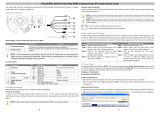
Figure 6. Camera module with camera cover removed.
6. Built-in speaker
7. MicroSD card slot
Insert a micro SDHC card for backup/
emergency recording and/or storage.
RESET pin hole
Use a sharp object to Press the Reset
button, the camera will be rebooted.
8. Light sensor for day/night switching
9. IR LEDs x3
10. Camera cover lock screw hole
11. Mounting screw hole/slot x3
12. Camera cover clips x3
13. Built-in microphone
14. DC12V Power connector
15. RJ45 Network connector
(PoE supported)
14
15
Figure 7. Ax68/Ax78 cabling.

9
Rev. 160824i3-TRNG-CAMS-68R_78R.indd
Important. Please Read:
• Use sealant at the locations shown on the mounting diagrams to maintain
IP66 rating when installing outside.
• It is the installer’s responsibility to ensure that the mounting surface is
suitable for the chosen installation method.
• Based on installation location and surface type, supplied screws and
anchors may not be adequate.
• Mounting hardware is site-specific and may need to be supplied by the
installer.
1
1
1
TOP
Drill Template
Hole A : for cables routed through the ceiling
Screw hole 1 : for Mounting Base
Figure 8. Surface Mount Template
3.3 Surface Mounting
1. Use the Surface Mount
Template to drill three (3)
6 mm (0.2”) screw holes at the
marked template positions on
the mounting surface.
2. Drill the cable opening at the
marked template position.
129.5
112.1
ø
30
3. Insert three (3) supplied screw
anchors into the drilled holes in
the mounting surface.
4. Use a Phillips screwdriver to insert
supplied screws into the screw
anchors. Leave enough screw
length protruding from the each
anchor to allow for the camera
body to be rotated onto the
screws.
Figure 9. Surface Mount - Steps 3-4.

10
i3-TRNG-CAMS-68R_78R.indd Rev. 160824
129.5
112.1
ø
30
129.5
112.1
ø
30
129.5
112.1
ø
30
5. Remove the camera cover.
Use a Phillips screwdriver to loosen
the safety lock screw, then grip the
camera cover and flex on one side,
towards the center.
Lift UP to remove.
6. Feed the camera cabling through
the cable opening drilled in the
mounting surface.
7. Slide the protruding mounting
screws through three matching
mounting screw holes on the
camera body and rotate the camera
clockwise to secure the camera
body on the mounting surface. Use
a Phillips screwdriver to tighten
three mounting screws in place.
8. Replace the camera cover.
Match up the safety lock screw
with the screw hole on the camera
body, then push straight down
onto the camera cover to engage
the clips. The camera cover will
re-attach.
9. Use a Phillips screwdriver to
re-tighten the safety lock screw.
Figure 10. Surface Mount - Steps 6-7.
Figure 11. Surface Mount - Step 8.
Figure 12. Surface Mount - Step 9.

11
Rev. 160824i3-TRNG-CAMS-68R_78R.indd
3.4 Wall Mount w/ Back Box and Gooseneck Bracket
1. Install the i3 Goose-neck
bracket (DB60) on the wall
surface using the hardware
and instructions supplied
with the goose-neck bracket.
Note on supplied mounting hardware and IP66 rating
Based on installation location and surface type, supplied screws and
anchors may not be adequate. Mounting hardware is site-specific
and may need to be supplied by the installer.
It is the installer’s responsibility to ensure that the mounting surface
is suitable for installation method.
Use sealant at the locations shown on the mounting diagrams to
maintain IP66 rating when installing outside.
Use silicone
to maintain IP66
rating
DB60 - Goose-neck
Bracket
DB78BB - Back box
Safety lock screw
2. Attach DB78BB back box to the
threaded end of the goose-
neck bracket DB60 and rotate
clockwise to attach the two
together. Use silicone sealer
as indicated on the diagram
to maintain IP66 rating when
installing outside.
Use silicone
to maintain IP66
rating
DB60 - Goose-neck
Bracket
DB78BB - Back box
Safety lock screw
3. Remove the camera cover.
Use a Phillips screwdriver to loosen
the safety lock screw, then grip
the camera cover and flex on one
side, towards the center. Lift UP to
remove.
4. Use a Phillips screwdriver to insert
three machine-type screws provided
with the DB78BB back box into the
screw holes on the back box.
Leave enough screw length
protruding to allow for the camera
body to be rotated onto the screws.
Figure 13. Wall-Mount - Step 2.
Figure 14. Wall-Mount - Step 4.

12
i3-TRNG-CAMS-68R_78R.indd Rev. 160824
5. Feed the camera cabling through the
gooseneck bracket.
6. Slide the protruding mounting screws
through three matching mounting
screw holes on the camera body
and rotate the camera clockwise
to secure the camera body on the
mounting surface. Use a Phillips
screwdriver to tighten three
mounting screws in place.
Use silicone
to maintain IP66
rating
DB60 - Goose-neck
Bracket
DB78BB - Back box
Safety lock screw
Figure 15. Wall-Mount - Step 6.
Use silicone
to maintain IP66
rating
DB60 - Goose-neck
Bracket
DB78BB - Back box
Safety lock screw
Use silicone
to maintain IP66
rating
DB60 - Goose-neck
Bracket
DB78BB - Back box
Safety lock screw
Figure 16. Wall-Mount - Step 7.
7. Replace the camera cover.
Match up the safety lock screw
with the screw hole on the camera
body, then push straight down
onto the camera cover to engage
the clips. The camera cover will
re-attach.
8. Use a Phillips screwdriver to
re-tighten the safety lock screw.
Figure 17. Wall-Mount - Step 8.

13
Rev. 160824i3-TRNG-CAMS-68R_78R.indd
3.5 Wall Mount w/ Angle Mount Bracket
Note on supplied mounting hardware and IP66 rating
Based on installation location and surface type, supplied screws and
anchors may not be adequate. Mounting hardware is site-specific
and may need to be supplied by the installer.
It is the installer’s responsibility to ensure that the mounting surface
is suitable for installation method.
Use sealant at the locations shown on the mounting diagrams to
maintain IP66 rating when installing outside.
1. Install the i3 angle-mount bracket
(DB78TSM) on the wall surface
using the hardware and instructions
supplied with the angle mount
bracket. Use silicone sealer as
indicated on the diagram to
maintain IP66 rating when installing
outside.
2. Remove the camera cover. Use a
Phillips screwdriver to loosen the
safety lock screw, then grip the
camera cover and flex on one side,
towards the center.
Lift UP to remove.
3. Use a Phillips screwdriver to insert
three machine-type screws provided
with the DB78BB back box into the
screw holes on the back box. Leave
enough screw length protruding to
allow for the camera body to be
rotated onto the screws.
4. Feed the camera cabling through the
angle-mount bracket opening.
Use silicone
to maintain IP66
rating
DB78TSM - Angle-mount
Bracket
Figure 18. Angle-Mount - Step 1.
Use silicone
to maintain IP66
rating
DB78TSM - Angle-mount
Bracket
Figure 19. Angle-Mount - Step 3.

14
i3-TRNG-CAMS-68R_78R.indd Rev. 160824
5. Slide the protruding mounting screws
through three matching mounting screw
holes on the camera body and rotate the
camera clockwise to secure the camera
body on the mounting surface. Use a
Phillips screwdriver to tighten three
mounting screws in place.
Use silicone
to maintain IP66
rating
DB78TSM - Angle-mount
Bracket
Figure 20. Angle-Mount - Step 5.
6. Replace the camera cover.
Match up the safety lock screw with
the screw hole on the camera body,
then push straight down onto the
camera cover to engage the clips.
The camera cover will re-attach.
7. Use a Phillips screwdriver to
re-tighten the safety lock screw.
Use silicone
to maintain IP66
rating
DB78TSM - Angle-mount
Bracket
Figure 21. Angle-Mount - Step 6.
Use silicone
to maintain IP66
rating
DB78TSM - Angle-mount
Bracket
Figure 22. Angle-Mount - Step 7.

15
Rev. 160824i3-TRNG-CAMS-68R_78R.indd
3.6 Wall Mount w/ Back Box
Note on supplied mounting hardware and IP66 rating
Based on installation location and surface type, supplied screws and
anchors may not be adequate. Mounting hardware is site-specific
and may need to be supplied by the installer.
It is the installer’s responsibility to ensure that the mounting surface
is suitable for installation method.
Use sealant at the locations shown on the mounting diagrams to
maintain IP66 rating when installing outside.
1. Install the i3 Back Box (DB78BB) on
the wall surface using the hardware
and instructions supplied with the
back box. Use silicone sealer as
indicated on the diagram to maintain
IP66 rating when installing outside.
Use silicone
to maintain IP66
rating
DB78BB - Back box
Use silicone
to maintain IP66
rating
DB78BB - Back box
2. Remove the camera cover. Use a
Phillips screwdriver to loosen the
safety lock screw, then grip the
camera cover and flex on one side,
towards the center.
Lift UP to remove.
3. Use a Phillips screwdriver to insert
three machine-type screws provided
with the DB78BB back box into the
screw holes on the back box. Leave
enough screw length protruding to
allow for the camera body to be
rotated onto the screws.
4. Feed the camera cabling through the
back box opening.
Figure 23. Wall-Mount - Step 1.
Figure 24. Wall-Mount - Step 3.

16
i3-TRNG-CAMS-68R_78R.indd Rev. 160824
5. Slide the protruding mounting screws
through three matching mounting
screw holes on the camera body
and rotate the camera clockwise
to secure the camera body on the
mounting surface. Use a Phillips
screwdriver to tighten three
mounting screws in place.
Use silicone
to maintain IP66
rating
DB78BB - Back box
Figure 25. Wall-Mount - Step 5.
6. Replace the camera cover.
Match up the safety lock screw with
the screw hole on the camera body,
then push straight down onto the
camera cover to engage the clips.
The camera cover will re-attach.
7. Use a Phillips screwdriver to
re-tighten the safety lock screw.
Use silicone
to maintain IP66
rating
DB78BB - Back box
Figure 26. Wall-Mount - Step 7.
Use silicone
to maintain IP66
rating
DB78BB - Back box
Figure 27. Wall-Mount - Step 8.

17
Rev. 160824i3-TRNG-CAMS-68R_78R.indd
3.7 Pendant Pole Mount
1. Use a 3/4” Electrical EMT Conduit
Fitting with a ridgid 3/4” pipe for this
type of installation.
Note on supplied mounting hardware and IP66 rating
Based on installation location and surface type, supplied screws and
anchors may not be adequate. Mounting hardware is site-specific
and may need to be supplied by the installer.
It is the installer’s responsibility to ensure that the mounting surface
is suitable for installation method.
Use sealant at the locations shown on the mounting diagrams to
maintain IP66 rating when installing outside.
Use silicone
to maintain IP66
rating
DB78BB - Back box
Safety lock screw
3/4” Electrical EMT
Conduit Fitting
Ridgid 3/4” pipe
2. Attach DB78BB back box to the
threaded end of the 3/4” Electrical
EMT Conduit Fitting and rotate
clockwise to attach the two together.
Use silicone sealer as indicated on the
diagram to maintain IP66 rating when
installing outside.
Figure 28. Pendant-Mount - Step 2.
3. Remove the camera cover.
Use a Phillips screwdriver to loosen
the safety lock screw, then grip the
camera cover and flex on one side,
towards the center.
Lift UP to remove.
4. Use a Phillips screwdriver to insert
three machine-type screws provided
with the DB78BB back box into the
screw holes on the back box.
Leave enough screw length
protruding to allow for the camera
body to be rotated onto the screws.
Use silicone
to maintain IP66
rating
DB78BB - Back box
Safety lock screw
3/4” Electrical EMT
Conduit Fitting
Ridgid 3/4” pipe
Figure 29. Pendant-Mount - Step 4.

18
i3-TRNG-CAMS-68R_78R.indd Rev. 160824
5. Feed the camera cabling through the
ridgid pipe bracket.
6. Slide the protruding mounting screws
through three matching mounting
screw holes on the camera body and
rotate the camera clockwise to secure
the camera body on the mounting
surface. Use a Phillips screwdriver to
tighten three mounting screws in place.
7. Replace the camera cover.
Match up the safety lock screw with
the screw hole on the camera body,
then push straight down onto the
camera cover to engage the clips.
The camera cover will re-attach.
8. Use a Phillips screwdriver to
re-tighten the safety lock screw.
Use silicone
to maintain IP66
rating
DB78BB - Back box
Safety lock screw
3/4” Electrical EMT
Conduit Fitting
Ridgid 3/4” pipe
Use silicone
to maintain IP66
rating
DB78BB - Back box
Safety lock screw
3/4” Electrical EMT
Conduit Fitting
Ridgid 3/4” pipe
Use silicone
to maintain IP66
rating
DB78BB - Back box
Safety lock screw
3/4” Electrical EMT
Conduit Fitting
Ridgid 3/4” pipe

19
Rev. 160824i3-TRNG-CAMS-68R_78R.indd
4.
Connecting Ax68R/78R to SRX-Pro Server
4.1 Network Topology Options
i3 SRX-Pro
Server
Crossover direct connection
LAN
i3 SRX-Pro
Server
Via Gigabit Switch
Connection Option 1 (Single camera)
Important: Must use 12V DC Power for this connection type. PoE not supported.
Connection Option 2 (Multiple cameras)
4.2 Hardware/Software Requirements
The following requirements must be met to achieve a successful network connection
with the Ax68R/78R-series IP camera.
SRX-Pro Server
• i3 SRX-Pro Version 3.0 or higher
• Latest GiPi adapter is installed. GiPi adapters can be downloaded from
i3 Downloads web page. (Please contact i3 Technical Support for more
information.)
• Windows XP, XPe, 7 Pro or 7e
• Internet Explorer Version 8.0 or later
• CPU: Intel Pentium Core 2 or higher
• Memory: 1GB or more
• VGA card--supporting DirectX 9.0 or above
Switch
A Gigabit Switch is required to monitor two or more cameras from the same
SRX-Pro Server.

20
i3-TRNG-CAMS-68R_78R.indd Rev. 160824
4.3 Configuring Internet Explorer for Video Display
Your Internet Explorer (v.8.0 or higher) must first be configured in order to properly
display video stream from your Annexxus camera.
Follow these instructions to configure your Internet Explorer browser.
Enable Cookies
1. In Internet Explorer window, click Tools -> Internet Options
2. Open Privacy tab, move the slider to “Low” or “Accept All Cookies”
3. Click Apply. Do not close the Internet
Options window.
Adjust Internet Security Settings
1. Open Security tab in the Internet
Options window
2. If the camera operates inside of the
Intranet, click the Intranet icon;
If the camera operates outside of the
Intranet, click the Internet icon.
3. Click Custom Level. Security
Settings - Internet Zone window will be
displayed.
4. Scroll down to the ActiveX controls
and plug-ins radio buttons and
configure as follows:
» Automatic prompting for ActiveX
controls -> Enable
» Download signed ActiveX
controls -> Prompt
(recommended)
» Download unsigned ActiveX
controls -> Prompt
» Initialize and script ActiveX not
marked as safe for scripting ->
Prompt
» Run ActiveX controls and plug-ins
-> Enable
/