RTS Mce-325 User manual
- Category
- Supplementary music equipment
- Type
- User manual

F.01U.193.228
Rev. 13
NOVEMBER/2013
USER INSTRUCTIONS
MODEL MCE-325
P
ROGRAMMABLE USER STATION

Bosch Security Systems, Inc.
Technical Manual
F.01U.193.228
Rev. 13
2 MCE-325 Programmable User Station
PROPRIETARY NOTICE
The product information and design disclosed herein were origi-
nated by and are the property of Bosch Security Systems, Inc.
Bosch reserves all patent, proprietary design, manufacturing, repro-
duction, use and sales rights thereto, and to any article disclosed
therein, except to the extent rights are expressly granted to others.
COPYRIGHT NOTICE
Copyright 2013 by Bosch Security Systems, Inc. All rights
reserved. Reproduction, in whole or in part, without prior written
permission from Bosch is prohibited.
*All other trademarks are property of their respective owners.
WARRANTY AND SERVICE INFORMATION
For warranty and service information, refer to the appropriate web
site below:
RTS Intercoms .............................. www.rtsintercoms.com/warranty
RTS Digital
RTSTW
AudioCom
RadioCom
Intercom Headsets.....................................................www.telex.com
CUSTOMER SUPPORT
Technical questions should be directed to:
Customer Service Department
Bosch Security Systems, Inc.
www.telex.com
TECHNICAL QUESTIONS EMEA
Bosch Security Systems Technical Support EMEA
http://www.rtsintercoms.com/contact_main.php
DISCLAIMER
The manufacturer of the equipment described herein makes
no expressed or implied warranty with respect to anything
contained in this manual and shall not be held liable for any
implied warranties of fitness for a particular application or
for any indirect, special, or consequential damages. The
information contained herein is subject to change without
prior notice and shall not be construed as an expressed or
implied commitment on the part of the manufacturer.
THE LIGHTNING
FLASH AND
ARROWHEAD
WITHIN THE
TRIANGLE IS A
WARNING SIGN
ALERTING YOU OF
“DANGEROUS
VOLTAGE” INSIDE
THE PRODUCT.
CAUTION: TO REDUCE
THE RISK OF ELECTRIC
SHOCK, DO NOT REMOVE
COVER. NO USER-
SERVICABLE PARTS
INSIDE. REFER
SERVICING TO
QUALIFIED SERVICE
PERSONNEL.
THE EXCLAMATION
POINT WITHIN THE
TRIANGLE IS A
WARNING SIGN
ALERTING YOU OF
IMPORTANT
INSTRUCTIONS
ACCOMPANYING
THE PRODUCT.
SEE MARKING ON BOTTOM/BACK OF PRODUCT.
WARNING: APPARATUS SHALL NOT BE EXPOSED TO DRIPPING OR
SPLASHING AND NO OBJECTS FILLED WITH LIQUIDS, SUCH AS VASES,
SHALL BE PLACED ON THE APPARATUS.
WARNING: THE MAIN POWER PLUG MUST REMAIN READILY OPERABLE.
CAUTION: TO REDUCE THE RISK OF ELECTRIC SHOCK, GROUNDING OF
THE CENTER PIN OF THIS PLUG MUST BE MAINTAINED.
WARNING: TO REDUCE THE RISK OF FIRE OR ELECTRIC SHOCK, DO NOT
EXPOSE THIS APPRATUS TO RAIN OR MOISTURE.
WARNING: TO PREVENT INJURY, THIS APPARATUS MUST BE SECURELY
ATTACHED TO THE FLOOR/WALL/RACK IN ACCORDANCE WITH THE
INSTALLATION INSTRUCTIONS.
This product is AC only.

Bosch Security Systems, Inc.
Technical Manual
MCE-325 Programmable User Station 3
F.01U.193.228
Rev. 13
Important Safety Instructions
1. Read these instructions.
2. Keep these instructions.
3. Heed all warnings.
4. Follow all instructions.
5. Do not use this apparatus near water.
6. Clean only with dry cloth.
7. Do not block any ventilation openings. Install in accordance with the
manufacturer’s instructions.
8. Do not install near any heat sources such as radiators, heat registers, stoves,
or other apparatus (including amplifiers) that produce heat.
9. Do not defeat the safety purpose of the polarized or grounding-type plug. A
polarized plug has two blades with one wider than the other. A grounding
type plug has two blades and a third grounding prong. The wide blade or the
third prong are provided for your safety. If the provided plug does not fit
into your outlet, consult an electrician for replacement of the obsolete outlet.
10. Protect the power cord from being walked on or pinched particularly at
plugs, convenience receptacles, and the point where they exit from the
apparatus.
11. Only use attachments/accessories specified by the manufacturer.
12. Use only with the cart, stand, tripod, bracket, or table specified by the
manufacturer, or sold with the apparatus. When a cart is used, use caution
when moving the cart/apparatus combination to avoid injury from tip-over.
13. Unplug this apparatus during lightning storms or when unused for long
periods of time.
14. Refer all servicing to qualified service personnel. Servicing is required
when the apparatus has been damaged in any way, such as power-supply
cord or plug is damaged, liquid has been spilled or objects have fallen into
the apparatus, the apparatus has been exposed to rain or moisture, does not
operate normally, or has been dropped.

Bosch Security Systems, Inc.
Technical Manual
F.01U.193.228
Rev. 13
4 MCE-325 Programmable User Station

Table
of
Contents
Bosch Security Systems, Inc.
Technical Manual
F.01U.193.288
Rev. 13
DESCRIPTION & SPECIFICATIONS ...................................................................................... 7
Description ...............................................................................................................................................7
General ................................................................................................................................................................. 7
Features ................................................................................................................................................................ 7
Front Panel Features .................................................................................................................................8
Channel Selector and Operation Buttons ............................................................................................................. 8
Volume Controls .................................................................................................................................................. 8
Sidetone Nulling Trimmers ................................................................................................................................. 8
Connections, Inputs and Outputs .............................................................................................................9
Front Panel ........................................................................................................................................................... 9
Panel Microphone Jack ........................................................................................................................................ 9
Rear Panel Features ................................................................................................................................10
Intercom Lines ................................................................................................................................................... 10
External Program Input ..................................................................................................................................... 10
Speaker Output .................................................................................................................................................. 10
Auxiliary Connector .......................................................................................................................................... 10
Programming ..........................................................................................................................................11
Power .....................................................................................................................................................11
Mounting Configuration ........................................................................................................................11
MCE-325 Specifications ........................................................................................................................12
General ............................................................................................................................................................... 12
Microphone Preamplifier ................................................................................................................................... 12
Headphone Amplifier ........................................................................................................................................ 12
Speaker Amplifier .............................................................................................................................................. 12
Power and Mechanical ....................................................................................................................................... 12
Connectors ......................................................................................................................................................... 12
MCS325 Specifications ..................................................................................................................................... 13
INSTALLATION ........................................................................................................................ 19
Internal Programming and Adjustments ................................................................................................19
General ............................................................................................................................................................... 19
Intercom Line Channel Configurations (DS1-DS3, J6, J7, J19, and J20) .............................................21
Front Panel Setup Mode Lock-out (DS4) .......................................................................................................... 24
ISO (DS5) .......................................................................................................................................................... 24
Remote Talk-off (DS7) ...................................................................................................................................... 24
VOX (DS8) ........................................................................................................................................................ 24
Program Assistant – IFB Option (J4, J5, J16-J18) ............................................................................................ 25
Balanced/Unbalanced Dynamic Microphone Selection (J24) ...........................................................................25
Headphone Sidetone Trimmer Adjustment (R37) .............................................................................................25
Speaker DIM Adjustment (R157) ......................................................................................................................25

Bosch Security Systems, Inc.
Technical Manual
6 MCE-325 Programmable User Station
F.01U.193.288
Rev. 13
Mechanical Installation ..........................................................................................................................25
Electrical Installation .............................................................................................................................27
AC Power and Fuse ........................................................................................................................................... 27
Intercom Lines J8, J9, J10 ................................................................................................................................. 27
General ........................................................................................................................................................... 27
Connector Pin Outs ........................................................................................................................................ 27
4-wire Termination ......................................................................................................................................... 28
Program Inputs, J14 and J15 .......................................................................................................................... 28
External Speaker, J27 ..................................................................................................................................... 28
Auxiliary Connector, J22 ............................................................................................................................... 29
4-wire CH A and B Input ............................................................................................................................ 29
Key Outputs – Expanded IFB Option ............................................................................................................ 29
Remote Microphone Switch ........................................................................................................................... 29
ISO Connection .............................................................................................................................................. 30
External Headset ............................................................................................................................................ 30
External Electret Microphone ........................................................................................................................ 30
External DC Power Source ............................................................................................................................ 31
Remote Speaker Mute Control ....................................................................................................................... 31
Front Panel Headset Connections ...................................................................................................................... 31
Headset Requirements .................................................................................................................................... 31
Headset Connections ...................................................................................................................................... 31
OPERATION ..............................................................................................................................33
General ...................................................................................................................................................33
Operating Instructions ............................................................................................................................33
Momentary/Latching Button action .................................................................................................................. 33
LED Indicators .................................................................................................................................................. 33
Channel Selection .............................................................................................................................................. 33
Panel Mic/Headset Mic Selection ..................................................................................................................... 34
Microphone On/Off ........................................................................................................................................... 34
Speaker On/Off .................................................................................................................................................. 34
Volume Adjustment .......................................................................................................................................... 34
Front Panel Sidetone Nulling Trimmer Adjustment ......................................................................................... 34
Sending and Receiving Call Signals ................................................................................................................. 35
Receiving a call: .......................................................................................................................................... 35
Using the Talk-Off Feature ............................................................................................................................... 35
Front Panel Programming ......................................................................................................................35
Activating Setup Mode ...................................................................................................................................... 35
Menu Selection/Ending Setup ........................................................................................................................... 35
Submenus .......................................................................................................................................................... 36
Channel ID ..................................................................................................................................................... 36
4-channel Listen ............................................................................................................................................. 36
Mono .............................................................................................................................................................. 36
Call Disable .................................................................................................................................................... 36
Button Lock .................................................................................................................................................... 37
Latch Disable ................................................................................................................................................. 37
Instant Mic ..................................................................................................................................................... 37
Reset ............................................................................................................................................................... 37

Bosch Security Systems, Inc.
Technical Manual
F.01U.193.228
Rev. 13
CHAPTER 1
Description & Specifications
Description
General
The MCE-325 is a 4-channel, programmable intercom station. It may be used as a headset station or, with the addition of the
MCS325 Modular Speaker, as a speaker station. It may be mounted in a console or equipment rack via optional mounting kits.
The MCE-325 can be used with either 2-wire or 4-wire intercom lines, or a combination of both. In this manual and in the
labeling on the MCE-325, references to CH 1, 2, 3, and 4 indicate 2-wire lines; references to 4-wire A and 4-wire B indicate
4-wire lines.
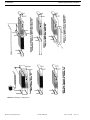
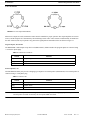
The MCE-325 can be interfaced to a variety of external devices including external program sources, 2-way radios, paging
systems, and satellite circuits. Some typical applications are shown in Figure 2 through Figure 10.
Features
Call Signaling Call signaling is accomplished using an inaudible (20kHz) signal to activate a call indicator
LED.
Remote Talk-Off Active, unattended remote station microphones may be deactivated by momentarily
injecting an inaudible (24kHz) signal into the corresponding intercom line. The MCE-325
can send and receive talk-off signals.
VOX Circuit The MCE-325 may be programmed for voice activation of the microphone.
Simple IFB Program audio assigned to a channel is interrupted during talk.
External Device Keying External devices, such as two-way radios, speaker mute relays, or paging systems may be
activated through key outputs at the auxiliary connector on the rear panel. The key outputs
may also be used to expand the simple IFB functions, allowing any number of MCE-325
stations to interrupt the program source and talk on the line.
Microphone Limiter The microphone preamplifier circuit contains a limiter, which helps to equalize voice levels.
Fully Programmable Retains programming even when power is shut off.

8 Description & Specifications MCE-325 Programmable User Station
Bosch Security Systems, Inc.
Technical Manual
F.01U.193.228
Rev. 13
Front Panel Features
Channel Selector and Operation Buttons
These buttons have two (2) modes of operation: standard operating mode and setup mode. The printing on the face of each
button indicates its function in standard operating mode; printing under each button indicates its setup mode function. (For
operation and programming instructions, see “Operation” on page 33.) An LED located above each button provides status
information.
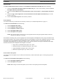
The MCE-325 is factory pre-programmed for 2-channel operation, with each channel having one (1) talk and one (1) listen
button. However, the MCE-325 may also be programmed so each channel selector button controls both talk and listen for a
single channel, permitting operation of up to four (4) intercom channels. Additionally, users may wish to customize the
identification of channels. With this in mind, a button kit has been supplied with the MCE-325 to allow you to customize the
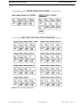
button labeling to suit your particular application. Figure 11 shows the available button caps as well as some typical button
configurations.
NOTE: The standard buttons are opaque. As a result, the front panel LEDs may not be visible when viewing the MCE-
325 from a low angle (such as when it is mounted high in an equipment rack). As a remedy for this problem,
clear buttons are available to allow the LED light to pass through. For order information, contact “Customer
Support” on page 2.
Volume Controls
CH1 (VOL 1): This control adjusts the volume of CH 1 and/or CH 3 to the left headphone when stereo headphones
are used. It adjusts the mono mix level of these channels when monaural headphones or an external
speaker is used.
CH2 (VOL 2): This control adjusts the volume of CH 2 and/or CH 4 to the right headphone when stereo
headphones are used. It adjusts the mono mix level of these channels when monaural headphones
or an external speaker is used.
PGM VOL: This control adjusts the mono mix of program A and program B (input at the rear panel and
assigned via internal programming) to the headphones and external speaker.
Sidetone Nulling Trimmers
These trimmers are adjusted to prevent acoustic feedback when using a panel microphone along with an external speaker.

MCE-325 Programmable User Station Description & Specifications 9
Bosch Security Systems, Inc.
Technical Manual
F.01U.193.228
Rev. 13
Connections, Inputs and Outputs
Front Panel
DYNamic MIC HEADSET: This connector accepts a stereo-earphone (5-pin connector), dynamic-mic headset (with or
without a mic on/off switch), or a mono-earphone, dynamic mic headset (4-pin
CARBon MIC HEADSET: This connector accepts a standard 3-conductor, ¼-inch phone plug. The necessary
phantom power is provided to power a carbon microphone or its electronic equivalent.
Panel Microphone Jack
The MCE-325 may be optionally fitted with a gooseneck panel microphone by removing the blanking plug located in the
upper-right corner of the front panel. The panel microphone jack accepts specially made gooseneck microphones (MCP-90
series), which are available from RTS.
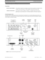
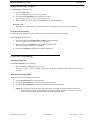
FIGURE 1. MCE-325 front and rear panel features

10 Description & Specifications MCE-325 Programmable User Station
Bosch Security Systems, Inc.
Technical Manual
F.01U.193.228
Rev. 13
Rear Panel Features
Intercom Lines
Connectors J8 and J9 are parallel-wired for loop-through connection to additional stations. These connectors are used either
for 2-wire CH 1 and CH 2 input/output, or 4-wire CH A output. (The 4-wire CH A input is connected at the auxiliary
connector.)
Connector J10 is used for 2-wire CH 3 and CH 4 input/output, or 4-wire CH B output, but no loop-through connector is
provided for these channels. (The 4-wire CH B input is connected at the auxiliary connector.)
The MCE-325 presents a bridging impedance of 10,000Ω to the intercom line, and is designed for use with intercom lines
having a 200Ω line terminating impedance. A 200Ω termination plug is supplied (connected to J10) to prevent channels three
and four from oscillating when the MCE-325 is in 2-channel mode.
External Program Input
Two (2) ¼-inch phone jacks are provided for external program input. The station accepts line-level, balanced input. The two
(2) program inputs are mixed internally, and may be assigned (through internal programming) to right headphone, left
headphone, external speaker, or any combination of these. In addition, program A may be assigned (through internal
programming) to 2-wire CH 3 or 4-wire CH A; program B may be assigned to 2-wire CH 4, but cannot be assigned to a 4-wire
channel. The program assigned to channels is interrupted during talk output.
Speaker Output
A ¼-inch phone jack is provided for connection of an external speaker (8Ω minimum impedance). The speaker output is
compatible with the MCS325 speaker.
Auxiliary Connector
Standard Options on the 25-pin, female, D-Sub connector are:
• Unswitched microphone output
• ISO connection to a VCP6A/VCP12A/VCP12B
• Microphone on/off switch
• Remote headset
• Remote panel microphone
• Separate inputs for +10 to +15 volts DC, and +17 to +24 volts DC
• Common/ground circuit
• 4-wire CH A and B inputs
• Remote speaker mute
• Key outputs

MCE-325 Programmable User Station Description & Specifications 11
Bosch Security Systems, Inc.
Technical Manual
F.01U.193.228
Rev. 13
Programming
Three (3) methods of programming are used:
1. Front panel programming via the channel selector and operation buttons.
2. Internal programming via circuit board DIP switches.
3. Internal programming via circuit board jumpers.
The most commonly programmed options are assigned to the front panel for convenience. Detailed information on internal
programming is provided in “Installation” on page 19. Detailed information on front panel programming is provided in
“Operation” on page 33.
Power
The MCE-325 is designed for local powering, and is supplied ready for use with either 110 or 220 VAC (but not both). The
unit may also be powered from an external DC source connected at the Auxiliary (J22) connector on the rear panel. For
information on changing the AC supply voltage configuration, or using DC power, see “Installation” on page 19.
Mounting Configuration
Mounting configurations are illustrated in Figure 14 on page 26 and include rack mount speaker station, console mount
headset station, rack mount headset station, desk top headset station, and portable speaker station. Some mounting
configurations may require a remotely located microphone or headset. These may be connected to the Auxiliary connector
(J22) on the back of the unit.

12 Description & Specifications MCE-325 Programmable User Station
Bosch Security Systems, Inc.
Technical Manual
F.01U.193.228
Rev. 13
MCE-325 Specifications
General
Bridging Impedance (to line) ................................................................................................................................10,000Ω typical
Noise Contribution to 200 Ω Line.......................................................................................................................................-90dBu
Call Signal Frequency ............................................................................................................................ 20kHz, crystal controlled
Talk-off Frequency ................................................................................................................................. 24kHz, crystal controlled
Microphone Preamplifier
Maximum Voltage Gain .........................................................................................................................................................54dB
Frequency Response............................................................................................................................... 100Hz to 8,000Hz, ±3dB
Input Impedance..................................................................................................................................................................1,000Ω
Limiter Range.........................................................................................................................................................................30dB
Headphone Amplifier
Maximum Voltage Gain .........................................................................................................................................................30dB
Frequency Response............................................................................................................................... 100Hz to 8,000Hz, ±3dB
Headphone Impedance ................................................................................................................................................. 50 to 600Ω
Output Power...................................................................................................................................................... 150mW into 50Ω
Output Voltage Level............................................................................................................................................................ 8Vp-p
Speaker Amplifier
Maximum Voltage Gain .........................................................................................................................................................30dB
Frequency Response............................................................................................................................... 100Hz to 8,000Hz, ±3dB
Speaker Impedance .......................................................................................................................................................... 8 to 16Ω
Output Power per Amplifier.........................................................................................................................................5W into 8Ω
Output Voltage Level.......................................................................................................................................................... 16Vp-p
Power and Mechanical
Power Requirements ............................................................................................................115 or 230VAC, 20VA max 60/50Hz
18 to 25VDC, 100 to 125mA quiescent, 900mA max
Dimensions............................................................................................... 1.72” H x 8.2” W x 8” D (44mm x 208mm x 203mm)
Weight .................................................................................................................................................................. 4.25lbs (1.93kg)
Material/Finish ............................................................................... Thermo-plastic front panel, aluminum case, light gray finish
Connectors
Intercom Line Connector .........................................................................XLR type, 3-pin (male-female loop through on 2-wire
CH 1 and 2, or 4-wire CH A; Female only on
2-wire CH 3 and 4, or 4-wire CH B
Dynamic Mic............................................................................................................................................ XLR type, 6-pin female
5-pin/4-pin female XLR
Carbon Mic........................................................................................................................................ ¼-inch phone jack, 3-circuit
Auxiliary Connector....................................................................................................................................25-pin, female, D-Sub
Program Inputs .................................................................................................................................. ¼-inch phone jack, 3-circuit
Speaker Output.................................................................................................................................. ¼-inch phone jack, 3-circuit
Panel Mic.....................................................................................................................¼-inch phone jack, metal busing, 3-circuit

MCE-325 Programmable User Station Description & Specifications 13
Bosch Security Systems, Inc.
Technical Manual
F.01U.193.228
Rev. 13
MCS325 Specifications
The MCS325 is designed for use with MCE-325, but may also be used as a general-purpose monitor for program material.
Impedance ...................................................................................................................................................... 8Ω (DCR5.5 to 7Ω)
Power Rating.................................................................................................................................................5W RMS continuous
Sensitivity...........................................................................................90dB ±2dB/2.83volts/one (1) meter on axis averaged over
one (1) octave bands centered at 250Hz, 500Hz, 1kHz,
2kHz, 4kHz, and 8kHz when enclosed in a sealed box
of 1.3 liters volume.
Frequency Response................................................................................ 200Hz to 10kHz ±4dB on 1/10 octave measurement in
1.3 liter sealed box.
Free Air Resonance .............................................................................................................................................. 200Hz to 250Hz
Distortion................................................................................................................................Less than 10% @ 5W at resonance.
Stray Magnetic Field .........................................................................................................Less than 1 gauss at 1cm from chassis.
Mechanical Noise....................................................................................... Unit to be free of buzzes and rattles at 5W sine wave
input from 100Hz to 10kHz.
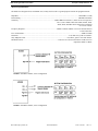
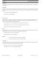
FIGURE 2. Standard 2-channel, 2-wire configuration
FIGURE 3. Standard 4-channel, 2-wire configuration

14 Description & Specifications MCE-325 Programmable User Station
Bosch Security Systems, Inc.
Technical Manual
F.01U.193.228
Rev. 13
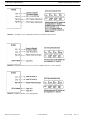
FIGURE 4. A 4-channel, 2-wire configuration with two (2) channels used for IFB’s
FIGURE 5. Configuration for one (1) or two (2) 2-wire channels and one (1) 4-wire channel
FIGURE 6. Standard 2-channel, 4-wire configuration

MCE-325 Programmable User Station Description & Specifications 15
Bosch Security Systems, Inc.
Technical Manual
F.01U.193.228
Rev. 13
FIGURE 7. Multiple interconnected stations in 4-channel, 2-wire configuration with two (2) channels used for IFB’s
FIGURE 8. Multiple interconnected stations using one (1) 4-wire intercom channel and two (2) 2-wire channels for IFB’s

16 Description & Specifications MCE-325 Programmable User Station
Bosch Security Systems, Inc.
Technical Manual
F.01U.193.228
Rev. 13
.
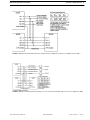
FIGURE 9. A 4-channel, 2-wire configuration with two (2) channels used for IFB’s (shown with TELCO interface)
FIGURE 10. Configuration for an ENG truck using one (1) 4-wire intercom channel and two (2) 2-wire IFB’s

MCE-325 Programmable User Station Description & Specifications 17
Bosch Security Systems, Inc.
Technical Manual
F.01U.193.228
Rev. 13
FIGURE 11. MCE-325 button configurations

18 Description & Specifications MCE-325 Programmable User Station
Bosch Security Systems, Inc.
Technical Manual
F.01U.193.228
Rev. 13

Bosch Security Systems, Inc.
Technical Manual
F.01U.193.228
Rev. 13
CHAPTER 2
Installation
Internal Programming and Adjustments
CAUTION: These servicing instructions are for use by qualified service personnel only. To reduce the risk of electrical
shock do not perform any servicing other than what is included in the operating instructions, unless you are
qualified to do so.
General
Prior to installing the MCE-325, it may be necessary to change some of the internal programming to suit your particular
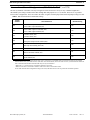
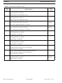
application. Table 1 on page 21 and Table 2 on page 22 list the functions for the DIP switches and jumpers which are used for
internal programming. Also shown are the default settings were pre-programmed at the factory.
If your application requires settings different from the defaults, you have to remove the top cover of the unit (see Figure 12 on
page 20) and make the required changes. If you do change the internal programming, it may be useful to note the changes for
future reference.
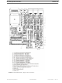
The locations of the dip switches and jumpers are illustrated in Figure 13 on page 23. Dip switch programming is
accomplished by setting switches to the off or on positions. Jumper programming is accomplished using shorting jumpers. By
inserting the jumpers to short the appropriate pins, a function is either assigned or not assigned. Pin 1 of each jumper is
indicated by a square symbol in Figure 13 for reference when making changes. Also, shown in Figure 13 are trimmers for
adjusting the sidetone and speaker dimming levels. Usage of the DIP switches, jumpers, and level trimmers is described in the
following paragraphs.

20 Installation MCE-325 Programmable User Station
Bosch Security Systems, Inc.
Technical Manual
F.01U.193.228
Rev. 13
FIGURE 12. Top cover removal
Page is loading ...
Page is loading ...
Page is loading ...
Page is loading ...
Page is loading ...
Page is loading ...
Page is loading ...
Page is loading ...
Page is loading ...
Page is loading ...
Page is loading ...
Page is loading ...
Page is loading ...
Page is loading ...
Page is loading ...
Page is loading ...
Page is loading ...
Page is loading ...
-
 1
1
-
 2
2
-
 3
3
-
 4
4
-
 5
5
-
 6
6
-
 7
7
-
 8
8
-
 9
9
-
 10
10
-
 11
11
-
 12
12
-
 13
13
-
 14
14
-
 15
15
-
 16
16
-
 17
17
-
 18
18
-
 19
19
-
 20
20
-
 21
21
-
 22
22
-
 23
23
-
 24
24
-
 25
25
-
 26
26
-
 27
27
-
 28
28
-
 29
29
-
 30
30
-
 31
31
-
 32
32
-
 33
33
-
 34
34
-
 35
35
-
 36
36
-
 37
37
-
 38
38


RTS Mce-325 User manual
- Category
- Supplementary music equipment
- Type
- User manual
Ask a question and I''ll find the answer in the document
Finding information in a document is now easier with AI