Page is loading ...

s
C2-010/C2-010-I ADSL2+
Router
User’s Manual
Rev: 1.3
2005/1210
No part of this publication may be reproduced in any form by any means without the
prior written permission. Other trademarks or brand names mentioned herein are
trademarks or registered trademarks of their respective companies.
This manual currently suits for C2-010/C2-010-I.
Downloaded from www.Manualslib.com manuals search engine


C2-010 / C2-010-I ADSL2+ Router User’s Guide
Contents
1.1 Device Introduction.......................................................................................................................1-1
1.2 Features........................................................................................................................................1-1
2.1 Packing List..................................................................................................................................2-1
2.2 Interfaces Introduction..................................................................................................................2-1
2.2.1 Front Panel................................................................................................................................2-1
2.2.2 Rear Panel................................................................................................................................2-2
2.3 Cable Connections.......................................................................................................................2-2
2.3.1 Connecting the ADSL Line........................................................................................................ 2-2
2.3.2 Connecting the ADSL2+ Router to the Ethernet LAN...............................................................2-2
2.3.3 Computer to ADSL2+ Router Connection.................................................................................2-3
2.3.4 Hub or Switch to ADSL2+ Router Connection..........................................................................2-4
2.4 Power on.......................................................................................................................................2-4
3.1 Set up TCP/IP on Your PC ..........................................................................................................3-1
3.2 Set up Proxy Service....................................................................................................................3-1
3.3 Configure IP Settings on Your PC ................................................................................................3-1
3.4 First Time Log on..........................................................................................................................3-2
4.1 Summary ......................................................................................................................................4-1
4.2 Configuring the WAN Connection................................................................................................. 4-2
4.2.1 Configuring a Bridged Connection for the WAN ....................................................................... 4-4
4.2.2 Static IP Address for Connection WAN..................................................................................... 4-5
4.2.3 Dynamic IP Address Connection for WAN................................................................................4-8
4.2.4 PPPoE and PPPoA Connection for WAN...............................................................................4-10
4.3 DHCP Configuration...................................................................................................................4-12
4.3.1 DHCP Server Settings for the LAN.........................................................................................4-12
4.3.2 Use the ADSL2+ Router for DHCP.........................................................................................4-12
4.3.3 Disabling the DHCP Server ....................................................................................................4-13
4.4 DNS Server Setting....................................................................................................................4-13
4.5 Configuring the LAN Connection................................................................................................4-13
5.1 UPnP Configuration...................................................................................................................... 5-2
5.2 Virtual Server Configuration .........................................................................................................5-3
5.3 SNMP Configuration..................................................................................................................... 5-4
5.4 Outbound IP Filter Configuration..................................................................................................5-5
5.5 Inbound IP Filter Configuration..................................................................................................... 5-6
5.6 Firewall ......................................................................................................................................... 5-8
5.7 DMZ..............................................................................................................................................5-9
5.8 RIP..............................................................................................................................................5-10
5.9 PPP............................................................................................................................................. 5-11
5.10 ADSL ..........................................................................................................................................5-12
5.11 ATM VCC....................................................................................................................................5-13
6.1 Administrator’s Settings................................................................................................................6-1
6.2 Configure System Time................................................................................................................ 6-2
I
Downloaded from www.Manualslib.com manuals search engine

C2-010 / C2-010-I ADSL2+ Router User’s Guide
6.3 Save ADSL2+ Router Configuration Settings............................................................................... 6-2
6.4 Restore Factory Default Settings..................................................................................................6-3
6.5 Save Configuration File to PC......................................................................................................6-3
6.6 Load Saved Configuration Files...................................................................................................6-3
6.7 Firmware Update..........................................................................................................................6-3
6.8 Tes t ...............................................................................................................................................6-4
7.1 Device Info....................................................................................................................................7-1
7.2 Log................................................................................................................................................7-1
7.3 Traffic Statistics.............................................................................................................................7-2
7.4 ADSL Status .................................................................................................................................7-3
8.1 Technical Specifications................................................................................................................8-1
II
Downloaded from www.Manualslib.com manuals search engine

C2-010 / C2-010-I ADSL2+ Router User’s Guide
1. Overview
The ADSL2+ Router provides integrated voice and data services over ADSL “Asymmetrical Digital
Subscriber Loop” WAN (Wide Area Network) connection.
1.1
1.2 Features
Device Introduction
The ADSL2+ Router is designed to provide a simple and cost-effective ADSL Internet connection for
individual computers through the Ethernet ports, or use it to bridge your Ethernet LAN to the Internet. The
ADSL2+ Router combines the benefits of high-speed ADSL technology and LAN IP management in one
compact and convenient package. ADSL technology enables many interactive multi-media applications such
as video conferencing and collaborative computing.
The ADSL2+ Router is easy to install and use. The ADSL2+ Router connects to computers or an
Ethernet LAN via a standard Ethernet interface. The ADSL connection is made using ordinary twisted-pair
telephone line with standard connectors. Multiple PCs can be networked and connected to the Internet using
a single Wide Area Network (WAN) interface and single global IP address.
Data rates up to 26 Mbps downstream
Bridging and routing capabilities
PPP and tunneling features
Firewall with Dynamic Host Configuration Protocol (DHCP), Network Address Translation (NAT), Point-
to-Point Tunneling Protocol (PPTP), and Layer 2 Tunneling Protocol (L2TP).
Supports ADSL, ADSL2, ADSL2+
DSL Forum TR-048-compliant DSL CPE auto-configuration
UPnP for seamless network interconnectivity
Comprehensive networking protocol support includes DHCP
Friendly web-based graphical user interface for configuration and management
Supports up to eight simultaneous virtual connections for a single ADSL account
Supports T1.413 issue 2, G.dmt and G.lite standards
Auto-handshake and rate adaptation for different ADSL flavors
Widest range of DSLAM interoperability
Supports bridged Ethernet over ATM (RFC 2684)
Upgradeable firmware through web
1-1
Downloaded from www.Manualslib.com manuals search engine


C2-010 / C2-010-I ADSL2+ Router User’s Guide
2. Installation Planning
Before installing the ADSL2+ Router, you should gather information and equipment needed to install the
device, then Install the hardware as instructed, connect the cables to the device and power on the ADSL2+
Router. Prior to accessing the web-based software built into the ADSL2+ Router, you should check the IP
settings on your computer and change them if necessary.
2-1
2.1
2.2
Packing List
Please check the package contents by comparing them with the following list:
One ADSL2+ Router
One telephone lines
One straight-through Ethernet Cable
One Power Adapter
Interfaces Introduction
2.2.1 Front Panel
Figure
2–1 Front Panel
Power
Steady green light indicates the unit is powered on. When the device is powered off this
remains dark.
Status
Lights steady green during power on self-test (POST). Once the connection status has been
settled, the light will blink green. If the indicator lights steady green after the POST, the system
has failed and the device should be rebooted.
ADSL:
Link/Act
Steady green light indicates a valid ADSL connection. This will light after the ADSL negotiation
process has been settled. A blinking green light indicates activity on the WAN (ADSL) interface.
LAN:
Link/Act
A solid green light indicates a valid link on startup. This light blinks when there is activity
currently passing through the Ethernet port.
Downloaded from www.Manualslib.com manuals search engine

C2-010 / C2-010-I ADSL2+ Router User’s Guide
2.2.2 Rear Panel
Ethernet port
− to your
PC’s
Ethernet port
Power input −
Connect power
adapter here
Factory Rese
t
Button
ADSL port −
Connect to the
ADSL line
Figure 2-2 Rear Panel
2.3 Cable Connections
After verifying proper environmental conditions such as temperature, humidity and power supply, users
may start the cable connections as following.
2.3.1 Connecting the ADSL Line
Use the ADSL cable included with the ADSL2+ Router to connect it to a telephone wall socket or
receptacle. Plug one end of the cable into the ADSL port (RJ-11 receptacle) on the rear panel of the ADSL2+
Router and insert the other end into the RJ-11 wall socket. If you are using a low pass filter device, follow the
instructions included with the device or given to you by your service provider. The ADSL connection
represents the WAN interface, the connection to the Internet. It is the physical link to the service provider’s
network backbone and ultimately to the Internet.
2.3.2 Connecting the ADSL2+ Router to the Ethernet LAN
The ADSL2+ Router may be connected to a single computer or Ethernet device through the 10BASE-TX
Ethernet port on the rear panel. Any connection to an Ethernet concentrating device such as a switch or hub
must operate at a speed of 10/100 Mbps only. When connecting the ADSL2+ Router to any Ethernet device
that is capable of operating at speeds higher than 10Mbps, be sure that the device has auto-negotiation
(NWay) enabled for the connecting port.
Use standard twisted-pair cable with RJ-45 connectors. The RJ-45 port on the ADSL2+ Router is a
crossed port (MDI-X). Follow standard Ethernet guidelines when deciding what type of cable to use to make
this connection. When connecting the ADSL2+ Router directly to a PC or server use a normal straight-
through cable. You should use a crossed cable when connecting the ADSL2+ Router to a normal (MDI-X)
port on a switch or hub. Use a normal straight-through cable when connecting it to an uplink (MDI-II) port on
a hub or switch.
The rules governing Ethernet cable lengths apply to the LAN to ADSL2+ Router connection. Be sure that
the cable connecting the LAN to the ADSL2+ Router does not exceed 100 meters.
2-2
Downloaded from www.Manualslib.com manuals search engine

ADSL2+ Router User’s Guide
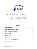
2.3.3 Computer to ADSL2+ Router Connection
Figure 2-3 Computer to ADSL2+ Router Connection
You can connect the ADSL2+ Router directly to a 10/100BASE-TX Ethernet adapter card (NIC) installed
on a PC using the Ethernet cable provided as shown in this diagram.
Cat 5 Ethernet
Cable
2-3
Downloaded from www.Manualslib.com manuals search engine

C2-010 / C2-010-I ADSL2+ Router User’s Guide
2.3.4 Hub or Switch to ADSL2+ Router Connection
Connect the ADSL2+ Router to an uplink port on an Ethernet hub or switch with a straight-through cable
as shown in the diagram below:
Figure2-5 Hub/Switch to ADSL2+ Router Connection
If you wish to reserve the uplink port on the switch or hub for another device, connect to any on the other
MDI-X ports (1x, 2x, etc.) with a crossed cable.
2.4 Power on
1) To power on the ADSL2+ Router, please follow the steps as instructed: Insert the AC Power Adapter cord
into the power receptacle located on the rear panel of the ADSL2+ Router and plug the adapter into a
suitable nearby power source.
2) You should see the Power LED indicator light up and remain lit. The Status LED should light solid
green and begin to blink after a few seconds.
2-4
Downloaded from www.Manualslib.com manuals search engine

C2-010 / C2-010-I ADSL2+ Router User’s Guide
3. Before Configuring ADSL2+ Router
The factory default settings of ADSL2+ Router optimized all functions so as to enable it to operate on
most network conditions. Usually, for the users with simple network topology, the default settings can meet
the basic requirements and don’t need to change. In order to access the web-based software built into the
ADSL2+ Router, you should check the IP settings on your computer and change them if necessary to access
web-based manager to configure the device.
3-1
3.1 Set up TCP/IP on Your PC
In order to configure your system to receive IP settings from the ADSL2+ Router it must first have the
TCP/IP protocol installed. If you have an Ethernet port on your computer, it probably already has TCP/IP
protocol installed. Please follow the instructions to check your IP protocol:
1) In Windows task bar, click the Start button, point to Settings>Network and Dial-up Connection> and
click on Local Connection.
2) Click on Properties> Select Internet Protocol (TCP/IP) and then Click Properties.
3) Click on the button labeled use the following IP address, Then you can set the IP address and Subnet
mask, for example, 192.168.1.100 and 255.255.255.0.
Note: If Internet Protocol (TCP/IP) does not display as an installed component, you must install it.
3.2
3.3
Set up Proxy Service
In Windows Internet Explorer, you can check if a proxy server is enabled using the following procedure:
1) Click on the START button, go to Settings and choose Control Panel.
2) In the Control Panel window, double-click on the Internet Options icon
3) Click the Connections tab and click on the LAN Settings button.
4) Verify that the “Use proxy server” option is NOT checked. If it is checked, click in the checked box to
deselect the option and click OK.
Configure IP Settings on Your PC
To use the web-based management software, launch your web browser software and use the LAN IP
address of the ADSL2+ Router to access the management software. The default LAN IP address of the
ADSL2+ Router is used in the Address bar of your web browser window. Type in http:// followed by the
default IP address, 192.168.1.1 in the address bar of the browser. The URL in the address bar should read:
http://192.168.1.1
Downloaded from www.Manualslib.com manuals search engine

C2-010 / C2-010-I ADSL2+ Router User’s Guide
3-2
3.4 First Time Log on
After inputting the forgoing IP address on URL address bar, a new window appears prompting you for a
user name and password needed to gain access the web configuration manager.
Figure 3-1. Log On Interface
Use the default system user name: admin and password: admin for first time set up. You can change
the password once you have established the ADSL connection. The user name and password allows any
computer on the same subnet as the ADSL2+ Router to access the web configuration manger. This
password can also be used to Telnet to the device through the Ethernet or the Internet interfaces.
Downloaded from www.Manualslib.com manuals search engine

C2-010 / C2-010-I ADSL2+ Router User’s Guide
4. Web-based Management
4-1
4.1 Summary
When you successfully login the Basic directory will display the ADSL2+ Router’s current connection
status − both for the WAN (Internet) and LAN (your home network) connections, as shown below. You can
begin the process of configuring your ADSL modem/ADSL2+ Router by clicking on the Advanced button in
the upper left-hand corner of the first Web page displayed. This will open the Wizard page, as shown below.
Click on a
button to
view the
menus
available in
that
directory
Figure 4-1. Web Manager – Basic Page
Figure 4-2. Web Manager – Wizard Page
Downloaded from www.Manualslib.com manuals search engine

C2-010 / C2-010-I ADSL2+ Router User’s Guide
4-2
Each tab displays menu buttons located in the left hand panel of the web interface. The table below lists
the menus for each directory in the web manager.
Directory Configuration and Read-only Menus
Home
Click the Home tab to access the Summary, WAN, DHCP, DNS, and LAN Configuration
menus.
Advanced
Click the Advanced tab to access the Virtual Server, Application, Filter, Firewall, NAT, DDNS,
and RIP menus.
Tools
Click the Tools tab to access the Administrator Settings (used to set the system user name
and password), System Time Configuration, System Settings (load and save configuration
files) and Firmware menus.
Status
Click the Status tab to view the Log, Diagnostic, and Statistics information windows.
Help
The Help menu presents links to pages that explain various functions and services provided
by the ADSL2+ Router.
Table 4-2 Options of Web-based page
4.2 Configuring the WAN Connection
To configure the ADSL2+ Router’s basic configuration settings, you can access the menus used to
configure WAN, DHCP, DNS and LAN settings from the Home directory. To access the WAN Settings menu,
click on the WAN link button on the upper left-hand side of the first window that appears when you
successfully access the web manager.
The WAN Settings menu is also used to configure the ADSL2+ Router for multiple virtual connections.
The next section contains information on how to configure the ADSL2+ Router for Multiple PVCs. Please
note that most users will require only single PVC. Select the connection type used for your account. The
menu will display settings that are appropriate for the connection type you select. Follow the instruction
below according to the type of connection you select in the WAN Settings menu. Your Internet Service
Provider (ISP) should provide the information you need to select the proper connection type.
Downloaded from www.Manualslib.com manuals search engine

ADSL2+ Router User’s Guide
Figure 4-3 WAN Current Settings Menu
Select the connection type used for your account. The menu will display settings that are appropriate for
the connection type you select. Follow the instruction below according to the type of connection you select in
the WAN Settings menu. Your Internet Service Provider (ISP) should provide the information you need to
select the proper connection type.
To configure the Router’s basic configuration settings without running the Setup Wizard, you can access
the menus used to configure WAN, LAN, DHCP and DNS settings directly from the Home directory. To
access the WAN Settings menu, click on the WAN link button on the left side of the first window that appears
when you successfully access the web manager.
The WAN Settings menu is also used to configure the Router for multiple virtual connections (Multiple
PVCs).
Note: you can configure up to seven different connections on your ADSL2+ Router ADSL
Modem/ADSL2+ Router by assigning a number to each configuration using the drop-down menu
corresponding to the ATM Interface heading. This could be useful if you have several ISPs and need to
configure the ADSL2+ Router differently for each. Most users will require only single PVC, however.
4-3
Downloaded from www.Manualslib.com manuals search engine

C2-010 / C2-010-I ADSL2+ Router User’s Guide
4.2.1 Configuring a Bridged Connection for the WAN
A bridged connection between your ISP and your LAN (the computers in your house or office) is the
simplest type of connection possible. The ADSL2+ Router will simply convert the incoming and outgoing
packets to the correct format for each side of the connection (Ethernet for the LAN, ATM for the WAN).
For a bridged connection it will be necessary for most users to install additional software (supplied by
your ISP) on any computer that will use the ADSL2+ Router for Internet access. The additional software is
used for the purpose of identifying and verifying your account, and then granting Internet access to the
computer requesting the connection (that is, the software supplied by your ISP will handle giving your
Username and Password to the computer at your ISP that will then connect you to the Internet). The
connection software requires the user to enter the User Name and Password for the ISP account. This
information is stored on the computer on the LAN, not in the ADSL2+ Router for a bridged connection.
Follow the instructions below to configure a Bridged connection for the WAN interface.
Figure 4-4 WAN Settings Menu – Bridge Mode
Note: Please note that the menu shown above will change depending on which WAN Type and Connection
Type you select.
To configure a Bridged mode connection, perform the steps listed below. Some of the settings do not need
to be changed the first time the device is set up, but can be changed later if you choose. See the table below
for a description of all the settings available in this menu.
1. Choose the Bridge Mode option from the WAN Settings pull-down menu.
2. Under the ATM Interface settings at the top of the menu (including VPI, VCI, and Virtual Circuit) should
not be changed unless you have been instructed to change them. However, if you are instructed to change
the VPI or VCI values, type in the values assigned for your account. Leave the ATM Interface and Virtual
Circuit setting at the default (Pcv0 and Enabled) values for now. This can be used later if you are
configuring multiple virtual circuits for your ADSL service.
3. Under the Bridge Mode heading, choose the Connection Type from the pull-down menu. This defines
both the connection type and encapsulation method used for your ADSL service. The available options are
1483 Bridged IP LLC and 1483 Bridged IP VC-Mux. If have not been provided specific information for the
Connection Type setting, leave the default setting.
4-4
Downloaded from www.Manualslib.com manuals search engine

ADSL2+ Router User’s Guide
4. When you are satisfied that all the WAN settings are configured correctly, click on the Apply button.
Note: Some accounts use PPP connection software for their Internet service connection. If you have been
given a CD with PPP connection software, install this now as instructed by your service provider. After the
ADSL2+ Router has rebooted it will negotiate the ADSL connection. Use the connection software to log on to
the ISP network and access the Internet.
4.2.2 Static IP Address for Connection WAN
When the Router is configured to use Static IP Address assignment for the WAN connection, you must
manually assign a global IP Address, Subnet Mask and Gateway IP Address used for the WAN connection.
Most users will also need to configure DNS server IP settings in the DNS Settings configuration menu (see
below). Follow the instruction below to configure the Router to use Static IP Address assignment for the WAN
connection.
To configure a Static IP Address connection, perform the steps listed below. Some of the settings do not
need to be changed the first time the device is set up, but can be changed later if you choose. See the table
below for a description of all the settings available in this menu.
Figure 4-5 WAN Settings Menu – Static IP Address
To configure a Static IP type connection for the WAN, follow these stpes:
1. Choose the Static IP Address option from the WAN Settings pull-down menu.
2. Under the ATM Interface settings at the top of the menu (including VPI, VCI, and Virtual Circuit) should
not be changed unless you have been instructed to change them. However, if you are instructed to change
the VPI or VCI values, type in the values assigned for your account. Leave the ATM Interface and Virtual
Circuit setting at the default (Pcv0 and Enabled) values for now. This can be used later if you are
configuring multiple virtual circuits for your ADSL service.
4-5
Downloaded from www.Manualslib.com manuals search engine

C2-010 / C2-010-I ADSL2+ Router User’s Guide
4-6
3. Under the Static IP heading, choose the Connection Type from the pull-down menu. This defines both the
connection type and encapsulation method used for your ADSL service. The available options are Bridged
IP LLC, Bridged IP VC-MUX, Routed IP LLC, Routed IP VC-MUX or IPoA.. If have not been provided
specific information for the Connection Type setting, leave the default setting.
4. Change the IP Address, Subnet Mask, Gateway Address and (if available) Secondary DNS Server IP
address as instructed by your ISP. These are the global IP settings for the WAN interface. This is the
“visible” IP address of your account. Your ISP should have provided these IP settings to you. For IPoA
(Classic IP over ATM) connections you may need to type in an additional IP address for a ARP Server
Address. If you are using an IPoA connection, ask your ISP if it is necessary to use an ARP (Address
Resolution Protocol) server.
5. Leave the MTU value at the default setting (default = 1400) unless you have specific reasons to change
this (see table below).
6. Most users will not need to change ATM settings. If this is the first time you are setting up the ADSL
connection it is recommended that you leave the Service Category settings at the default values until you
have established the connection. See the table on page האיגש !תרדגומ הניא הינמיסה. for a description of the
parameters available for ATM traffic shaping.
7. When you are satisfied that all the WAN settings are configured correctly, click on the Apply button.
8. The new settings must be saved and the Router must be restarted for the settings to go into effect. To
Save & Reboot the Router, click on the Tools directory tab and then click the Save & Reboot menu
button. In the Save and Reboot menu, click the Reboot button under Force the DSL-300T to system
restart. The Router will save the new settings and restart. Upon restarting the Router will automatically
establish the WAN connection.
Additional settings for Static IP Address connections:
Static IP
Address
Parameters
Description
Connection
Type
This specifies the connection type and the encapsulation method used for your Static IP
Address connection. The options available are Bridged IP LLC, Bridged IP VC-MUX, Routed
IP LLC, Routed IP VC-MUX or IPoA.
IP Address
This is the permanent global IP address for your account. This is the address that is visible
outside your private network. Get this from your ISP.
Subnet
Mask
This is the Subnet mask for the WAN interface. Get this from your ISP.
Gateway
Address
This is the IP address of your ISP’s Gateway router. It provides the connection to the Router
for IP routed traffic that is outside your ISP’s network. That is, this will be the primary
connection from the Router to most of the Internet. Get this IP address from your ISP.
Primary
DNS
Address
This is the IP address of the first choice for Domain Name Service (DNS) used to match the
named URL web address used by most browsers with the actual global IP address used for
a web server. Usually this will be a server owned by the ISP. Get this IP address from your
ISP.
Secondary
DNS
Address
This is the second choice for a DNS server. Get this IP address from your ISP.
Default
Route
Enabled/Disabled − this sets the router as the default route between the PCs on your LAN
and the WAN (Internet). This should normally be enabled.
Downloaded from www.Manualslib.com manuals search engine

ADSL2+ Router User’s Guide
4-7
Route
NAT
Enabled/Disabled − this enables or disables NAT (Network Address Translation) on the
router. This should normally be enabled.
IGMP
Enabled/Disabled − this enables or disables IGMP (Internet Group Management Protocol) on
the router. This should normally be enabled.
Downloaded from www.Manualslib.com manuals search engine

C2-010 / C2-010-I ADSL2+ Router User’s Guide
4.2.3 Dynamic IP Address Connection for WAN
A Dynamic IP Address connection configures the Router to automatically obtain its global IP address from
a DHCP server on the ISP’s network. The service provider assigns a global IP address from a pool of
addresses available to the service provider. Typically the IP address assigned has a long lease time, so it will
likely be the same address each time the Router requests an IP address.
To configure a Dynamic IP Address connection, perform the steps listed below. Some of the settings do not
need to be changed the first time the device is set up, but can be changed later if you choose. See the table
below for a description of all the settings available in this menu.
Figure 4-6 WAN Settings Menu – Dynamic IP Address
1. Under the ATM Interface settings at the top of the menu (including VPI, VCI, and Virtual Circuit)
should not be changed unless you have been instructed to change them. However, if you are instructed
to change the VPI or VCI values, type in the values assigned for your account. Leave the ATM
Interface and Virtual Circuit setting at the default (Pcv0 and Enabled) values for now. This can be
used later if you are configuring multiple virtual circuits for your ADSL service.
2. Under the Dynamic IP heading, choose the Connection Type from the pull-down menu. This defines
both the connection type and encapsulation method used for your ADSL service. The available options
are 1483 Bridged IP LLC and 1483 Bridged IP VC-Mux. If have not been provided specific information
for the Connection Type setting, leave the default setting.
3. Some ISPs record the unique MAC address of your computer’s Ethernet adapter when you first access
their network. This can prevent the Router (which has a different MAC address) from being allowed
access to the ISPs network (and the Internet). To clone the MAC address of your computer’s Ethernet
adapter, type in the MAC address in the Cloned MAC Address field and click the Clone MAC
Address button.
4. Leave the MTU value at the default setting (default = 1400) unless you have specific reasons to
change this (see table below).
4-8
Downloaded from www.Manualslib.com manuals search engine
1/51