Page is loading ...

Do's
• Do - Read all the instructions before commencing installation.
• Do - Install each fan with a double pole isolating switch.
• Do - Make sure the mains supply is switched off before attempting to make electrical
connections or carry out any maintenance or cleaning.
• Don't - Install these fans in any window/panel which is less than 4mm thick.
Guarantee
Customers outside UK - see international below.
•
UK: The fan is guaranteed against defects for 3 years from the date of purchase.
• Xpelair reserve the right to repair or replace at their option.
• Please keep your purchase receipt.
• If you have any problems, contact Xpelair's Head Office at the address shown below.
Technical advice and service
Customers outside UK - see international below.
UK: Xpelair have a comprehensive range of services including:
• Free technical advice help-desk from Engineers on all aspects of ventilation.
• Free design service, quotations and site surveys.
• Service and maintenance contracts to suit all requirements.
Please ask for details:
• By telephone on Techline: +44 (0)8709 000430
•
By fax on Techfax: +44 (0)8709 000530
•
At the address below.
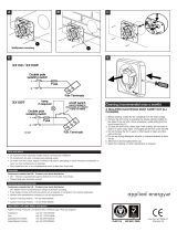
Head Office, UK Sales Office and Spares
Applied Energy Products Ltd, Morley Way, Peterborough, PE2 9JJ England
Telephone:
+44 (0)1733 456789
Fax: +44 (0)1733 310606
Sales/Spares Hotline: +44 (0)8709 000420
Sales/Spares Faxline: +44 (0)8709 000520
http:\\www.xpelair.co.uk
International
• Guarantee: Contact your local distributor or Xpelair direct for details.
• Technical Advice and Service: Contact your local Xpelair distributor.
Part No. 22178AA
Issue C

I
LAS CIARE QUESTO FOGLIETTO DI ISTRUZIONI
INSIEME AL VENTILATORE, PER USO DA PARTE
DELL'UTENTE.
18 7
(Continued)
5. Make all connections within the Isolating Switch.
WARNING: Do not make any connections to the Electrical Supply at this
stage.
For Australia only:
These models are permanently connected to the supply and
operation is controlled by a remote switch. They should be directly wired to the
supply through an approved 10A wall mounted surface switch with at least 3mm
clearance between contracts.
5 Preparing the hole
If installing in a window, get a ready-cut pane to the dimensions given in Fig. 1.
If installing in a wall:
1. Make sure that the centre of the hole is located at least 205mm from the edges
of the wall.
2.Check there are no buried pipes of cables in the wall or obstructions on
the outside e.g. Electricity, Gas, Water.
3. Mark on the wall the centre of the hole and drill right through.
4. Draw a circle on this centre to suit the wall duct.
5. Cut the hole. Do not cut right through the wall.
(The recommended method is to drill a series of holes, close together, around the
edge of the cutting line and remove the brick between the holes with a chisel.
Warning: eye protection must be worn).
6. Go outside and cut a hole in the outer wall, repeating the process described
above.
7. Fit the ducting.
8. Make good the hole. Allow the Mortar to set before continuing the Fan
installation.
6 Separate the Fan from the Inner Clamp Plate
1. Remove the inner grill and back draught shutter by first removing the screw
from the underside of the grille then unclipping the bottom of the grille, the top of
the grille can then be released by unclipping the top corner. The shutter can then
be unclipped. NOTE: The top of the grille can only be released when the screw is
removed and the bottom of the grille has been released (Fig. 2).
2. Unscrew the four cross-headed screws and lift off the Fan (Fig. 3).
7 Mount the Fan in the hole (Fig. 4)
Xpelair recommended that the instructions of this section are carried out by two
people.
If working above Ground Floor level, appropriate safety precautions must be
observed.
If installing the fan in a window, fix the three rubber edge protectors (packed
separately) at equal distances around the lip of the Outer Clamp Plate.
1. Attach the Ladder Strips (packed separately) to the Outer Clamp Plate.
2. Hold the Outer Grille up to the outside of the wall or window so that the lip of
the Outer Clamp Plate protrudes into the hole.
3. Hold the Inner Clamp Plate to the inside of the wall or window and guide the
Ladder Strips from the Outer Clamp Plate through the slots in the Inner Clamp
Plate.
4. Insert the slotted screws (packed separately) into the pockets around the
ladder Strip slots.
5. Tighten the screws carefully to make a good seal.
Do not overtighten.
6. Trim the Ladder Strips back to the required length, if necessary remove any
sharp edges.
8 Refit the Fan to the Inner Clamp Plate
1. Fit the Fan Assembly onto the Inner Clamp Plate (Fig. 3).
2. Make sure that the Ladder Strips go inside the Fan Assembly so they will not
get caught in the blades.
3. Tighten up the four screws.
Do not overtighten.
9 Wire the electrical connections
1. Remove the Fan Connector Plate carefully by unscrewing the two screws (Fig.
5). The Connector Assembly parts are contained loosely behind this plate.
2. Remove the two cable clamp screws (Fig. 8).
3. If required, feed the cable through the grommet (packed separately) in order to
fit to the cable entry of the Connector Plate.
♦If installing a GX9 with an on/off switch:
1. Wire the Fan Connector as shown in Fig. 6a.
2. Set the Fan Selector Switch to Position 1 for intake, Position 2 for extract or
Position 3 for "open shutter only" (Fig. 7).
♦If installing a GX9 with a controller:
1. Refer to the installation instructions for the controller.
2. If wiring to an existing controller, contact Xpelair Technical Services or in
export markets, the Xpelair distributor.
3. Set the Fan Selector Switch to Position 3 if using a controller providing variable
speed and/or direction. Otherwise, set the Fan Selector Switch to Position 1 for
intake, Position 2 for extract or Position 3 for "open shutter only" (Fig. 7).
♦If installing a GXC9 :
1. Wire the Fan Connector as shown in Fig. 6b.
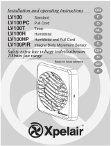
!º Fitting the Cable Clamp
♦For the GX9:
For cable up to 8mm diameter, clamp the cable as shown in Fig. 8a.
For cable equal to or greater than 8mm and up to 11.5mm diameter, clamp the
cable shown in Fig. 8b.
For cable greater than 11.5mm diameter use the conduit entry provided.
♦For the GXC9:
For cable upto 6mm diameter, clamp the cable as shown in Fig. 8a.
For cable equal to or greater than 6mm and upto 10mm diameter, clamp the
cable as shown in Fig. 8b.
For cable greater than 10mm diameter use the conduit entry provided.
!¡ Fitting the Connector to the Fan
1. Ensure the cable is firmly retained by the clamp.
2. Assemble the Fan Connector by snapping the Cover over the
Connector (Fig. 9).
3. Plug the Fan Connector into the Fan Assembly.
4. Refit the Connector Plate.
5. Refit the Backdraft Shutter.
6. Refit the Inner Grille.
7. Switch off the mains electrical supply and remove fuses.
8. Connect the cable from the isolation switch to the electrical supply writing.
9. Replace the fuses, and switch on the mains electrical supply.
♦ For fixed wiring circuits the protective fuse for the appliance must not
exceed 5A.
!™ Operating the Fan
GX9 (switch operated):
To switch on and off, use the switch on the wall or ceiling.
GX9
(controller operated):
Refer to the instructions for the controller.
♦ The shutters are operated by a silent thermo-actuator which has a time delay
on opening (30-50 secs) and closing (3 mins).
GXC9 (cord operated):
To switch on, pull down the cord and then release it. Repeat to switch off.
!£ Trickle Ventilation
♦ Trickle Ventilation is equivalent to that provided by an air brick or similar
device.
1. Remove the inner grill and back draught shutter by first removing the screw
from the underside of the grille then unclipping the bottom of the grille, the top of
the grille can then be released by unclipping the top corner. The shutter can then
be unclipped. NOTE: The top of the grille can only be released when the screw is
removed and the bottom of the grille has been released (Fig. 2).
♦ To allow trickle ventilation:
2. Release the Shutter Return Spring as shown in Fig. 10.
3. Re-position the Shutter Return Spring into the L-shaped slot.
4. Raise the Operating Bar to latch into position.
♦ To fully close the shutters and stop any backdraught:
5. Unlatch the Shutter Return Spring and re-position into the short slot.
6. Refit the Back Draught Shutter and Inner Grille.
!¢ Cleaning
1. Before cleaning, isolate the fan from the mains supply. Allow 3 minutes for the
impeller to stop rotating and the powered shutter to close.
2. Remove the inner grill and back draught shutter by first removing the screw
from the underside of the grille then unclipping the bottom of the grille, the top of
the grille can then be released by unclipping the top corner. The shutter can then
be unclipped. NOTE: The top of the grille can only be released when the screw is
removed and the bottom of the grille has been released (Fig. 2). WARNING: The
fan will still operate when the inner grille is removed.
3. Remove the impeller by unscrewing the knob at the front of the impeller.
anticlockwise.
4. Clean the inner grille, back-draught shutter and impeller by immersing in warm
soapy water. Dry thoroughly.
Do not immerse the fan in water or other liquids to clean any other parts of the
fan.
5. Refit the impeller by locating it over the motor shaft and aligning the arrow on
the impeller with the white dot on the motor. Make sure the impeller is seated
correctly.
6. Refit the knob making sure the ratchet at the rear of the knob is fully engaged.
♦ Never use strong solvents to clean the fan.
♦ Apart from cleaning, no other maintenance is required.
Inner Grille.........................................."A" Ladder Strips.................................."F"
Back Draught Shutter........................."B" Connector Plate.............................."G"
Fan Assembly ....................................."C" Rating Plate...................................."H"
Inner Clamp Plate..............................."D" Selector Switch (GX9 only)............"J"
Outer Clamp Plate/Grille....................."E" Cord (GXC9 only)..........................."K"
USING YOUR FAN
LOOKING AFTER YOUR FAN
KEY (For Fig. 11)
/