Page is loading ...


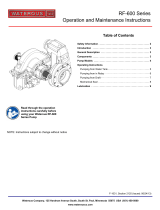
Table of Contents
Safety 4
Safety Precautions 4
Introduction 7
Using this Document 7
Viewing the Document Electronically 7
Printing the Document 7
Additional Documentation 7
Product Overview 8
CM Series Pump Overview 8
Pressure Mode 8
Volume Mode 8
Pump Components—Top 10
Pump Components—Bottom 11
Transfer Valve Actuator Control Panel—Electric Version 12
Transfer Valve Manual Override Actuator—Optional 13
Transfer Valve Actuator Control Panel—Manual Version 14
Operation 15
Understanding Operation Safety 15
Switching to Pressure Mode 16
Switching to Volume Mode 17
Pumping from the On-Board Tank 18
Pumping from Hydrant or Relay 19
Pumping from Draft 20
Storing the Pump 21
Maintenance 22
Maintenance Schedule 22
Adjusting the Packing Glands 23
Replacing the Intake Screen—Optional 24
Replacing the Bolt-On Anode—Optional 25
Replacing the Threaded Anode—Optional 26

4 | 28
Safety Introduction Product Overview Oper ation Maintenance
Safety Precautions
• Read and understand all the associated documentation before you begin
operating the product.
• Contact Waterous when you have questions about operating or maintaining
the equipment.
NOTICE
Before Operation
• Read and understand all
the instructions provided.
• Check all fluid levels
and replenish if necessary.
• Remove all shipping plugs
and install the operation
plugs or caps.
NOTICE
Pump Damage
•
• Pump damage occurs
when operating without
adequate water supply.
• Do not operate the pump
without adequate water
supply.
• Read and understand all the notices and safety precautions.
• Do not operate the equipment when safety guards are removed.
• Do not modify the equipment.
NOTICE
• Do not allow fluid in the
lines to freeze.
• Remove all freezable fluid
from the lines before
storing the apparatus.
Freeze Damage
NOTICE
Pump Damage
• Storing the pump partially
full causes undesirable
corrosion.
• Always store the pump
completely full or empty.

5 | 28
Safety Introduction Product Overview Oper ation Maintenance
Safety Precautions
NOTICE
• Do not prime the pump for
more than 1 minute.
• Operating the priming pump
more than 1 minute can
damage the motor or the
motor solenoid.
Priming Pump Damage
• Discharge ejected at high
pressure can cause serious
injury and damage.
High Pressure
• Direct discharge away from
people and equipment.
NOTICE
• Not following maintenance
procedures can damage
your equipment.
• Perform all maintenance
procedures as required.
Maintenance
Make sure the shift unit is
in the proper mode before
operation.
Unexpected movement
can cause injury or death.
Sudden Unexpected
Movement
•
•

6 | 28
Safety Introduction Product Overview Oper ation Maintenance
Safety Precautions
• Do not operate beyond
recommended pressure.
• Liquid ejected at high
pressure can cause
serious injury.
High Pressure
• Do not touch the surface
during operation—allow
it to cool after operating.
• Hot surfaces can burn you.
Hot Surface
• Do not operate if water
temperature exceeds
160ºF (71ºC).
• Hot liquid can scald you.
Hot Liquid
Read and understand all instructions following this symbol.

7 | 28
Safety Introduction Product Overview Oper ation Maintenance
Use this document to install and operate your Waterous equipment. Understand
the following conditions before continuing with the document:
• The instructions may refer to options or equipment that you may not have
purchased with your system.
• The illustrations in this document are intended to convey concepts. Do not
use the illustrations to determine physical attributes, placement, or
proportion.
• Understand that your application may require additional steps, that are not
described in the illustrations or instructions, to perform the installation.
• The equipment described in this document is intended to be installed by a
person or persons with the necessary skills and knowledge to perform the
installation.
• The equipment described in this document is intended to be operated by a
person or persons with the basic knowledge of operating similar equipment.
• The information in this document is subject to change without notice.
This document is divided into the following sections:
Safety
This section describes general precautions and alert symbols that are in this
document.
Introduction
This section is an overview of the document.
Product Overview
This section describes the components that make up the system.
Oper ation
This section describes the equipment operation.
Maintenance
This section describes maintenance procedures.
Using this Document
Use the guidelines below when viewing this document.
Viewing the Document Electronically
• View this document in landscape orientation.
• Use the table of contents to navigate directly to that section.
• Text with this appearance is linked to a reference.
Printing the Document
• The document is viewed the best when printed in color.
• The print on both sides and flip on long edge features can provide the
best results.
• Use a 3-ring binder to store the document.
Additional Documentation
Additional documentation is available through the MyWaterous login at
Waterousco.com. Use your serial number to gain access to the service parts
list associated with your system. Dimensional drawings are available through
the Waterous Service department.

8 | 28
Safety Introduction Product Overview Oper ation Maintenance
CM Series Pump Overview
The CM series pump is capable of operating in 2 modes. The 2-stage design allows you to operate the pump in pressure or volume mode. An electric or manual
panel-mounted controller operates the transfer valve in the pump that directs the flow to operate the pump in either mode. The pump is available with many intake
and discharge options. Understand that this instruction may not include all the options in your application.
Pressure Mode
In pressure mode, the 2 stages operate in series. The fist stage sends pressurized water to the second stage. The second stage further pressurizes the water
before sending it into the pump discharge at a maximum pressure of 600 psi (41 bar).
Volume Mode
In volume mode, both stages operate in parallel. Each stage flows water directly into the pump discharge to provide maximum flow.

Notes

10 | 28
Safety Introduction Product Overview Oper ation Maintenance
Pump Components—Top
1
2
3
2
FeatureFeature DescriptionDescription
1Transfer valve actuator This actuator operates the transfer valve that switches the pump between pressure and volume mode. Depending on your
application, it operates manually or electrically. Note: The transfer valve actuator can be mounted on the top or the bottom
of the pump.
2Intake screen This filters debris and aids with corrosion protection—optional.
3Anode This is an anode (bolt-on style shown) that aids in corrosion protection—optional.


12 | 28
Safety Introduction Product Overview Oper ation Maintenance
Transfer Valve Actuator Control Panel—Electric Version
TRANSFER VALVE
PRESSURE
VOLUME
2
4
1
3
FeatureFeature DescriptionDescription
1Pressure LED This illuminates when the transfer valve is in pressure mode.
2Pressure button This moves the transfer valve into pressure mode.
3Volume LED This illuminates when the transfer valve is in volume mode.
4Volume button This moves the transfer valve into volume mode.


14 | 28
Safety Introduction Product Overview Oper ation Maintenance
Transfer Valve Actuator Control Panel—Manual Version
2
1
3
FeatureFeature DescriptionDescription
1Pressure LED This illuminates when the transfer valve is in pressure mode.
2Volume LED This illuminates when the transfer valve is in volume mode.
3Handle This moves the transfer valve into pressure or volume mode.

15 | 28
Safety Introduction Product Overview Oper ation Maintenance
Understanding Operation Safety
Understand that each application is unique. Options included or not included with your application determine the operation of your specific system. It is incumbent
upon the operators to develop operational protocols that include robust safety considerations and industry best practices before operating the system. Use the
information in this section to guide you in developing operating protocols for your application.
Make sure the shift unit is
in the proper mode before
operation.
Unexpected movement
can cause injury or death.
Sudden Unexpected
Movement
•
•
Understand the safety concerns associated with
shifting the pump transmission in to pump mode.
• Discharge ejected at high
pressure can cause serious
injury and damage.
High Pressure
• Direct discharge away from
people and equipment.
Understand the safety concerns associated with the
discharge and pump pressure during operation.
• Drain the pump after use
and before servicing.
• Liquid ejected at high
pressure can cause
serious injury.
High Pressure
Understand the safety concerns associated with the
discharge and pump pressure before servicing.
• Do not touch the surface
during operation—allow
it to cool after operating.
• Hot surfaces can burn you.
Hot Surface
Understand the safety concerns associated with the
pump surface temperature before servicing.
• Do not operate if water
temperature exceeds
160ºF (71ºC).
• Hot liquid can scald you.
Hot Liquid
Understand the safety concerns associated with the
pump raising the water temperature during
operation.

16 | 28
Safety Introduction Product Overview Oper ation Maintenance
Switching to Pressure Mode
TRANSFER VALVE
PRESSURE
VOLUME
12
7
6
5 5
4
3 3
Use the illustrations and instructions to operate the
pump in pressure mode.
High Pressure Hazard: Changing the
position of the transfer valve with the pump
operating may result in a significant change
in discharge pressure. The operator may
need to adjust the engine speed to maintain
the desired discharge pressure. Reducing
the engine to idle speed before transferring
will minimize the change in discharge
pressure.
1 Press and hold the button until the
volume LED illuminates to place the pump into
pressure mode.
Note: Reduce the discharge pressure to
250 psi (17.2 bar) when you change
between modes electrically.
2 Rotate the handle in the direction indicated on
the label until the pressure LED illuminates to
place the pump into pressure mode.
Note: Reduce the discharge pressure to
75 psi (5.2 bar) when you change
between modes manually.
3 Water enters the intake and flows into the first
stage.
4 Water flows from the first stage through the
transfer valve into the second stage.
5Flaps in the second stage isolate the flow where
it builds additional pressure.
6 Water flows out of the second stage into the
discharge.
7 Water exits the pump discharge.

17 | 28
Safety Introduction Product Overview Oper ation Maintenance
Switching to Volume Mode
TRANSFER VALVE
PRESSURE
VOLUME
1 2
4
5
3 3
4
Use the illustrations and instructions to operate the
pump in volume mode.
High Pressure Hazard: Changing the
position of the transfer valve with the pump
operating may result in a significant change
in discharge pressure. The operator may
need to adjust the engine speed to maintain
the desired discharge pressure. Reducing
the engine to idle speed before transferring
will minimize the change in discharge
pressure.
1 Press and hold the button until the
volume LED illuminates to place the pump into
volume mode.
Note: Reduce the discharge pressure to
250 psi (17.2 bar) when you change
between modes electrically.
2 Rotate the handle in the direction indicated on
the label until the volume LED illuminates to
place the pump into volume mode.
Note: Reduce the discharge pressure to
75 psi (5.2 bar) when you change
between modes manually.
3 Water enters the intake and flows to either
stage.
4 Each stage flows water into the discharge.
5 Water exits the pump discharge.

18 | 28
Safety Introduction Product Overview Oper ation Maintenance
Pumping from the On-Board Tank
Follow the instructions to operate the pump from the on-board tank.
High Pressure Hazard: Prior to connection of hoses, caps or other
closures with pump intake or pump discharge connections, relieve
pressure by opening drains.
Scalding Water Hazard: When operating the pump, be sure to open at
least one discharge valve slightly to prevent the pump from overheating.
If the pump runs for a few minutes completely closed, it may heat the
water enough to scald someone when the valve is opened. Overheating
can damage the packing, seals and other pump parts. If the apparatus
builder has installed a by-pass system or other provision designed to
prevent overheating, opening a discharge valve may be unnecessary.
Unexpected Truck Movement: Failure to properly shift transmission in
accordance with the transmission operating instructions may result in
unexpected truck movement which may result in serious personal injury
or death.
1. Engage the pump—refer to the pump transmission instructions for your
application.
2. Switch transfer valve to desired position.
NOTE: As a general rule, keep the transfer valve in pressure position when
pumping up to 2/3 of the rated capacity of the pump and in volume
when pumping more than 2/3 of the rated capacity. If high pressure
is required (more than 200 psi, 13.8 bar), operating the pump in the
PRESSURE position may be necessary even if it means closing one
or more valves to reduce volume and avoid cavitation. The transfer
valve may be changed from one position to the other while operating
the pump. Decreasing the discharge pressure will make this easier. If
the pump has a manually operated transfer valve, slow engine speed
to reduce the discharge pressure to 75 psi (5.2 bar) or less. With the
electric transfer valve, reducing the discharge pressure is necessary
only if it exceeds 250 psi (17.3 bar).
3. Open valve(s) in piping between water tank.
4. Allow about 30 seconds for water to ow into pump.
NOTE: Priming the pump may be necessary because of air trapped in
piping.
5. Accelerate engine to obtain desired discharge pressure and capacity.
6. Set relief valves or other pressure governing device to desired pressure.
After operation do the following:
High Pressure Hazard: Prior to removal of hoses, caps or other
closures with pump intake or pump discharge connections, relieve
pressure by opening the drains.
1. Disengage the pump—refer to the pump transmission instructions for your
application.
2. If pumping other than clean water during operation, ush the pump until all
contaminants are removed.
3. Close all drains and install intake and discharge caps.

19 | 28
Safety Introduction Product Overview Oper ation Maintenance
Pumping from Hydrant or Relay
Follow the instructions to operate the pump from hydrant or relay.
High Pressure Hazard: Prior to connection of hoses, caps or other
closures with pump intake or pump discharge connections, relieve
pressure by opening drains.
Scalding Water Hazard: When operating the pump, be sure to open at
least one discharge valve slightly to prevent the pump from overheating.
If the pump runs for a few minutes completely closed, it may heat the
water enough to scald someone when the valve is opened. Overheating
can damage the packing, seals and other pump parts. If the apparatus
builder has installed a by-pass system or other provision designed to
prevent overheating, opening a discharge valve may be unnecessary.
Unexpected Truck Movement: Failure to properly shift transmission in
accordance with the transmission operating instructions may result in
unexpected truck movement which may result in serious personal injury
or death.
1. Engage the pump—refer to the pump transmission instructions for your
application.
2. Open intake, hydrant and other valves as necessary to allow water to enter
the pump.
NOTE:
intake with water.
3. Switch transfer valve to desired position.
NOTE: As a general rule, keep the transfer valve in pressure position when
pumping up to 2/3 of the rated capacity of the pump and in volume
when pumping more than 2/3 of the rated capacity. If high pressure
is required (more than 200 psi, 13.8 bar), operating the pump in the
pressure position may be necessary even if it means closing one or
more valves to reduce volume and avoid cavitation. The transfer valve
may be changed from one position to the other while operating the
pump. Decreasing the discharge pressure will make this easier. If the
pump has a manually operated transfer valve, slow engine speed to
reduce the discharge pressure to 75 psi (5.2 bar) or less. With the
electric transfer valve, reducing the discharge pressure is necessary
only if it exceeds 250 psi (17.3 bar).
4. Open discharge valves and accelerate engine to obtain desired discharge
pressure and capacity.
5. Set relief valves or other pressure governing device to desired pressure.
NOTE: Do not attempt to pump more water than is available from the
hydrant. Always make sure the intake pressure compound gauge
minimum intake pressure of 10 psi (0.7 bar) when pumping from
hydrant to prevent a “soft” intake hose from collapsing.
After operation do the following:
High Pressure Hazard: Prior to removal of hoses, caps or other
closures with pump intake or pump discharge connections, relieve
pressure by opening the drains.
1. Disengage the pump—refer to the pump transmission instructions for your
application.
2. If pumping other than clean water during operation, ush the pump until all
contaminants are removed.
3. Close all drains and install intake and discharge caps.
4. Switch transfer valve back and forth once.

20 | 28
Safety Introduction Product Overview Oper ation Maintenance
Pumping from Draft
Follow the instructions to operate the pump from draft.
High Pressure Hazard: Prior to connection of hoses, caps or other
closures with pump intake or pump discharge connections, relieve
pressure by opening drains.
Scalding Water Hazard: When operating the pump, be sure to open at
least one discharge valve slightly to prevent the pump from overheating.
If the pump runs for a few minutes completely closed, it may heat the
water enough to scald someone when the valve is opened. Overheating
can damage the packing, seals and other pump parts. If the apparatus
builder has installed a by-pass system or other provision designed to
prevent overheating, opening a discharge valve may be unnecessary.
Unexpected Truck Movement: Failure to properly shift transmission in
accordance with the transmission operating instructions may result in
unexpected truck movement which may result in serious personal injury
or death.
1. Position vehicle as near as possible to water supply.
2. Avoid humps and sharp bends in intake hose. Make sure no part of hose is
higher than pump intake inlet. Air pockets in intake hose may cause loss of
prime or erratic pump action, and may reduce pump capacity.
3. Make sure all intake connections are tight and discharge valves are closed.
4. Immerse intake strainer at least two feet below water surface to prevent
pump from drawing air. Whirlpools forming above intake strainer indicate
that the strainer is too close to the surface of the water.
5. Make sure intake strainer is far enough from the bottom to prevent sand,
gravel and other foreign matter from being drawn into the pump.
6. Switch transfer valve to desired position.
NOTE: As a general rule, keep the transfer valve in pressure position when
pumping up to 2/3 of the rated capacity of the pump and in volume
when pumping more than 2/3 of the rated capacity. If high pressure
is required (more than 200 psi, 13.8 bar), operating the pump in the
PRESSURE position may be necessary even if it means closing one
or more valves to reduce volume and avoid cavitation. The transfer
valve may be changed from one position to the other while operating
the pump. Decreasing the discharge pressure will make this easier. If
the pump has a manually operated transfer valve, slow engine speed
to reduce the discharge pressure to 75 psi (5.2 bar) or less. With the
electric transfer valve, reducing the discharge pressure is necessary
only if it exceeds 250 psi (17.3 bar).
7. Open discharge valves and accelerate engine to obtain desired discharge
pressure and capacity.
8. Set relief valves or other pressure governing device to desired pressure.
NOTE: Do not attempt to pump more water than is available from the
hydrant. Always make sure the intake pressure compound gauge
minimum intake pressure of 10 psi (0.7 bar) when pumping from
hydrant to prevent a “soft” intake hose from collapsing.
After operation do the following:
High Pressure Hazard: Prior to removal of hoses, caps or other
closures with pump intake or pump discharge connections, relieve
pressure by opening the drains.
1. Disengage the pump—refer to the pump transmission instructions for your
application.
2. If pumping other than clean water during operation, ush the pump until all
contaminants are removed.
3. Close all drains and install intake and discharge caps.
4. Switch transfer valve back and forth once.
/