Page is loading ...

TOOLS FOR EASY INSTALLATION
• Utility Knife
• #2 Phillips Drive bit
• ¾” Socket
• Socket Wrench
• T25 Torx Bit
• T30 Torx Bit
• 8mm Socket
• Marker
STEP 1.
Prior to Installation:
A) Fit: Verify you have ordered the correct Body Cladding for your
vehicle make and model and check their fit.
B) Painting : (Optional) if paint is desired it must be done prior to
installing flares on the vehicle clean outer surface with a good
grade degreaser. DO NOT USE LACQUER THINNER OR
ENAMEL REDUCER AS A DEGREASER. Wipe outer surface
thoroughly with a tack rag prior to paint.
Paint flares using a high quality enamel, or polyurethane
automotive paint. (Application of a primer coat is optional)
Kit Supplied Hardware:
INSTALLATION PROCEDURES
IMPORTANT NOTE: Ambient Temperature – During installation: the vehicle, the parts, and the tape
need to be between 60° and 110°F for proper adhesion. Vehicle surface must also be wiped with alcohol
to remove dirt and grease, which may also affect adhesion. Failure to maintain proper installation
temperature and surface preparation may result in the part not functioning correctly.
If you are installing Side Panels only,
please skip to Step 5.
STEP 2: Driver Side Rear Corner
Installation
A) Remove the Gas Tank Outer Flange using a T25 Torx
Bit, retaining factory hardware for later use. (8 screws)
See Figure #1.
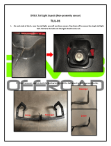
B) Remove the Tail Light Lens using a #2 Philips
screwdriver (4 screws), then remove tail light housing
using 10mm socket wrench (3 screws) retaining the
factory hardware for later use. See Figure #2.
Jeep TJ 97-Up Trail Armor
Side Panels
for use with Bushwacker Flares
Set Part # 14002
Rev A 5/04
Figure #1 – Remove Gas Tank Outer Flange
Tuf-Lok
Fastener
(6 per)

C) Remove the License Plate and License Plate holder
(4 screws) using a 10mm socket wrench, retaining
factory hardware for later use. See Figure #2.
D) Peel red vinyl backing from the tape on the Driver Side
Rear Corner Piece.
E) Using the cut outs and screw holes in the Driver Side
Rear Corner Piece as a guide, align the Rear Corner
Piece with corresponding cut outs and screw holes in
the vehicle. Take care not to exert pressure on the
adhesive tape before you have aligned the Rear
Corner Piece properly.
F) Once you have checked for proper location apply 30
pounds of pressure per square inch to areas of the
parts opposite tape pads to ensure proper tape
adhesion. (See Important Note above)
G) Re-install the Gas Tank Outer Flange and Tail Light
using the factory hardware.
H) Insert a square plastic grommet into each of the
square holes in the license plate area.
I) Re-install the License Plate using supplied 10mm hex
screws (4 screws)
STEP 3: Passenger Side Rear
Corner Installation
A) Remove the Tail Light Lens using a #2 Philips
screwdriver (4 screws), then remove tail light housing
using 10mm socket wrench (3 screws) retaining the
factory hardware for later use. See Figure #2.
B) Peel red vinyl backing from the tape on the Passenger
Side Rear Corner Piece.
C) Using the screw holes in the Passenger Side Rear
Corner Piece as a guide, align the Rear Corner Piece
with the corresponding screw holes in the vehicle. Take
care not to exert pressure on the adhesive tape before
you have aligned the Rear Corner Piece properly.
D) Once you have checked for proper location apply 30
pounds of pressure per square inch to areas of the parts
opposite tape pads to ensure proper tape adhesion.
E) Reinstall the Tail Light using the factory hardware.
NOTE: Some adjustment to rear fender flares may be
required for uniform gap between rear corner and
flare.
STEP 4: Rear Panel Installation
A) Remove the spare tire using a ¾” Socket. Retain the
factory hardware (3 lug nuts). See Figure #3.
B) Using a T30 Torx Bit, remove the screw holding the
lower rubber tire stop in place, retaining both the screw
and the rubber tire stop. See Figure #4.
C) Peel red vinyl backing from the tape on the Rear Panel.
Figure #2 – Remove Tail Light & License Plate
Fi
g
ure #3
–
Remove Spare Tire
Figure #4 – Remove Tire Stop

D) Using the hole in the center of the Rear Panel as a
guide, align with the hole located in the vehicle. Take
care not to exert pressure on the adhesive tape before
you have aligned the Rear Panel properly.
E) Once you have checked for proper location apply 30
pounds of pressure per square inch to areas of the parts
opposite tape pads to ensure proper tape adhesion.
F) Reinstall the lower rubber tire stop and Spare Tire using
the factory hardware. See Figure #5.
STEP 5: Side Panel Installation
A) Remove the factory stone guard using an 8mm Socket
and ratchet. See Figure #6.
B) Prior to Installation, look at part numbers inscribed in the
plastic to identify right and left side panel.
(Right – 14002 R; Left – 14002 L)
C) Peel red vinyl backing from the tape on the Side Panels.
D) Using the holes on the underside of the Side Panel as a
guide, align with 3 factory holes on the underside of the
vehicle. Take care not to exert pressure on the adhesive
tape before you have aligned the side Panel properly.
See Figure #7.
E) Attach underside edge of the Side Panel to the vehicle
using supplied Tuf-Lok fasteners.
F) Apply 30 pounds of pressure per square inch to areas of
the parts opposite tape pads to ensure proper tape
adhesion.
STEP 6: Front Panel Installation
A) Remove the factory Front Panel, using 10mm socket
wrench (4 bolts) retaining the factory hardware for later
use. See Figure #8.
B) Using holes as a guide align the Front Panel and fasten
with factory hardware removed previously.
Figure #5 – Reinstall Tire Stop & Tire
Figure #6 – Remove Stone Guard
Figure #7 – Install Side Panel
Figure #8 – Factory Front Panel Removed
6710 N. CATLIN AVE. • PORTLAND, OR 97203
•
503-283-4335
•
1-800-234-8920 (USA AND CANADA) • FAX 503-283-3007
/