Page is loading ...

VULCAN-HART COMPANY, P.O. BOX 696, LOUISVILLE, KY 40201-0696, TEL. (502) 778-2791
INSTALLATION &
OPERATION MANUAL
For additional information on Vulcan-Hart Company or to locate an authorized
parts and service provider in your area, visit our website at www.vulcanhart.com
FORM 30914 Rev. A (Jan. 2003)
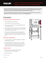
VSC SERIES STEAMERS
WITH STEAM COIL REGENERATOR
MODEL
VSC2
VSC3
MODEL VSC2

– 2 –
© VULCAN-HART COMPANY, 2003

– 3 –
Installation, Operation and Care of
VSC SERIES STEAMERS
With Steam Coil Regenerator
SAVE THESE INSTRUCTIONS
GENERAL
Model VSC2 and VSC3 Steamers have two or three pressurized steaming compartments for cooking
vegetables, fish, eggs and other foods.
The heat exchanger in the cabinet base requires approximately 200 lb per hour of steam at 30 to 50 psi.
(Refer to Steam Connection.)
Accessory 12" x 20" stainless steel pans are available, solid or perforated, in 2.5", 4" and 6" depths.
Each compartment has a 0 to 60 minute timer. (The buzzer requires manual shutoff.) Doors cannot be
opened during pressurized cooking.
An optional steam take-off connection (
3
/4" NPT) can provide steam for adjacent equipment.
ACCOMMODATION
MODEL COMPARTMENTS
TOTAL NUMBER OF PANS
NUMBER OF PANS PER
COMPARTMENT
2.5" Depth 4" Depth 6" Depth 2.5" Depth 4" Depth 6" Depth
VSC2 2 16 8 4
842
VSC3 3 24 12 6

– 4 –
INSTALLATION
UNPACKING
Immediately after unpacking, check for possible shipping damage. If the steamer is found to be
damaged, save the packaging material and contact the carrier within 15 days of delivery.
LOCATION
Before installing, verify that the electrical supply agrees with the specifications on the data plate.
Position the steamer in its final location. Check that there are sufficient clearances to service the
controls, for door swings, etc., so there will be no problem in making the required supply and drain
connections.
Allow enough space between any other piece of equipment or a wall for service access. Service for
the controls for the upper steamer compartments requires access to the upper left side panel. Service
on the cabinet base may require access to the left and/or right side panels.
INSTALLATION CODES AND STANDARDS
In the United States, the steamer must be installed in accordance with:
1. State and local codes.
2. National Electrical Code, ANSI/NFPA No. 70 (latest edition). Copies may be obtained from the
National Fire Protection Association, Batterymarch Park, Quincy, MA 02269.
3. NFPA Standard # 96
Vapor Removal from Cooking Equipment,
latest edition, available from the
National Fire Protection Association, Batterymarch Park, Quincy, MA 02269.
LEVELING
Using a spirit level or pan of water, level the appliance; then elevate the right side about 1/8" (3 mm)
to assure proper compartment drainage. After installation, bolt and anchor the appliance securely to the
floor. Seal bolts and rear flanged feet with an NSF approved sealer (Silastic or equivalent).
EXHAUST HOOD
An exhaust system should be located directly above the steamer to exhaust steam and heat generated
by the steamer.

– 5 –
PLUMBING CONNECTIONS
WARNING: PLUMBING CONNECTIONS MUST COMPLY WITH APPLICABLE SANITARY, SAFETY
AND PLUMBING CODES.
Water Supply Connection
The water filter, provided, must be installed in the water supply line going to the filtered water inlet or
your steamer warranty may be voided. For incoming water supply line pressures, refer to the water filter
manual shipped with the water filter. Follow the recommendations contained in it. Water pressure to the
steamer should be 20 to 60 psi.
Water Requirements
Proper water quality can improve the taste of the food prepared in the steamer, reduce liming in the
steam generator and extend equipment life. Local water conditions vary from one location to another.
Ask your municipal water supplier for details about your local water supply before installation.
Recommended water parameters are included in the water filter manual shipped with the steamer;
follow the recommendations contained in it.
Presence of sediment, silica, excess chlorides or other dissolved solids may lead to a recommendation
for alternate form(s) of water treatment. Be sure to test the water with the test strip and register the
results using the registration card or by visiting vulcanhart.com.
Drain Connection(s)
The steamer drain should be piped to a floor drain near the steamer. There should be no solid drain
connection; an open gap between the steamer and the floor drain is required.
Draining Requirements
Temperatures in the boiler can reach as high as 240°F (116°C). Local codes will require that the
temperature of the drain water be 140°F (60°C) or lower. At the end of the day when purging the boilers,
some provision for lowering the water temperature must be provided by the user or installer to meet this
code requirement.
STEAM TAKE-OFF CONNECTION (Optional)
When connecting adjacent equipment to the steam take-off connection (
3
/4" NPT), follow the equipment
manufacturer’s instructions. Steam capacity should be carefully evaluated. If the optional steam take-
off connection is provided on your steamer and is not connected to adjacent equipment, it should be
plugged or capped.

– 6 –
STEAM CONNECTION
An adequate amount of steam must be delivered to the steamer to assure consistent steam cooking.
Where possible, supply the steamer with a separate line from the steam source. If the steamer must
be supplied from a line supplying other appliances, the pipe sizes and pressure must be verified.
REQUIRED STEAM INPUT
Allow for elbows, pipe length and valves when calculating pressure loss (see example below).
Supply only clean, dry steam to the steamer. Water can condense in the supply line during idle periods,
which will impede the flow of steam. The steam supply line should be level or run slightly downward
toward the steamer, and a Ball Float Trap should be installed near the steamer to drain out condensed
steam from the supply line (Fig. 1).
Fig. 1
STEAM LINE—PRESSURE LOSS EQUIVALENTS
Example: A supply line with 1" diameter pipe has a total of 50' of pipe, three elbows and one globe valve.
The total equivalent length = 50' + 3 x 2.2' + 23' = 79.6'. Multiply times the loss rate of 1 psi/10' yields
a pressure loss of about 8 psi. Therefore, 40 psi at the source would deliver 32 psi at the steamer.
If the supply line were
3
/4" diameter pipe, the total equivalent length = 50' + 3 x 1.8' + 18' = 73.4'. Multiply
times the loss rate of 1 psi / 7.5 feet yields a pressure loss of about 10 psi. Therefore, 40 psi at the source
would deliver 30 psi at the steamer.
eziSepiP etaRssoL
teeFraeniLnissoLtnelaviuqE
)remaetstaisp03(etaRyrevileD
°09 evlaVelgnA evlaVebolG
3
/
4
DI"teef5.7/isp1teef8.1teef01teef81rh/sbl561
DI"1teef01/isp1teef2.2teef21teef32rh/sbl582
2CSVledoM 3CSVledoM
rh/sbl07rh/sbl501

– 7 –
ELECTRICAL CONNECTIONS
WARNING: ELECTRICAL AND GROUNDING CONNECTIONS MUST COMPLY WITH THE
APPLICABLE PORTIONS OF THE NATIONAL ELECTRICAL CODE AND/OR OTHER LOCAL
ELECTRICAL CODES.
WARNING: DISCONNECT THE ELECTRICAL POWER TO THE MACHINE AND FOLLOW
LOCKOUT / TAGOUT PROCEDURES.
Refer to the electrical diagram located behind the access panel or cabinet door on the steamer.
Service Connections
Fig. 2

– 8 –
OPERATION
WARNING: THE STEAMER AND ITS PARTS ARE HOT. USE CARE WHEN OPERATING,
CLEANING OR SERVICING THE STEAMER.
COMPARTMENT CONTROLS (Fig. 3)
Fig. 3
Timer (0 to 60 minutes) - Sets the steam time for the compartment.
Indicator Light - Timed cycle is in progress when lit.
Selector Switch - Pressurized means top compartment operates at 6 psi.
Operating Handle - Pull out to send steam to the compartment, lock the door and enable
operation.
Push in to silence buzzer at end of cycle.
Door Latch - Holds door closed and prevents door from fully opening until
operating handle is pushed in. Move the door latch to the left to fully
open the door after steam and condensate drain (1 minute). The
handwheel is turned fully counterclockwise.
Handwheel - Turn clockwise to seal door at start of cycle. After pressure release
at end of cycle, turn counterclockwise to open.
Buzzer (not shown) - Sounds an audible signal when timer cycle is complete. To silence
buzzer, push in operating handle.
Pressure Gauge - Indicates steam pressure. Reads 6 psi with compartments inactive
and 4.5 to 6 psi during a cooking cycle.

– 9 –
STEAM REGENERATOR CONTROLS (Inside Cabinet)
Main Power Switch - ON begins generation of clean steam by the heat exchanger. You
should allow 20 minutes to generate steam.
OFF opens the Automatic Blowdown valve. This empties the heat
exchanger by releasing both water and steam to the drain. This
should be done at least once daily to remove sediment, lime or
scale.
Pilot Light (green) - Indicates main power is ON.
Boiler Pressure Gauge - Should read 9 to 13 psi during operation and 0 psi during shutdown.
Water Level Sight Glass - This assembly indicates the water level, and should be checked at
least once a day. The correct water level is one-half the height of
the glass. Extreme murkiness indicates the boiler should be
cleaned.
Water Level Control - While ON, briefly open the manual valve under the float chamber
once each week to remove any sediment that might accumulate
and seize the floats. The float chamber is beside the regenerator
tank.
Safety Valve - This valve will release (pop off) if boiler pressure exceeds 15 psi.
Once a week, this valve should be tripped during operation to make
sure it functions properly.
Pressure Regulator - Reduces the steam pressure from the boiler to the steamer
compartments to 6 psi. Twice a year, unscrew the large hex head
plug located at the bottom of the regulator and remove and clean
the strainer. Carefully reassemble.
STEAMING
Each steaming compartment is controlled by its own controls. When a compartment is not operating,
the drain is open and the steam inlet valve from the boiler is closed. Food, properly portioned and in
appropriate solid or perforated pans, is placed on rack supports (or wire shelves) in the steaming
compartment. After closing and sealing the door, setting the timer and pulling out the operating handle,
the steam inlet valve from the heat exchanger opens, allowing steam at a pressure of 6 psi to enter the
compartment. Air from the sealed compartment exits through the vent until the temperature reaches
180°F (82°C); then the vent closes, and the compartment can become pressurized. Steaming
continues until the timer reaches “0” and the buzzer sounds. To silence the buzzer, push in the
operating handle. Wait 1 minute for steam or hot water to drain away. Open the door and remove the
cooked food.
The cabinet (lower portion of steamer) contains the heat exchanger which has a steam coil in a
pressurized tank. The steam coil is supplied with steam from an outside source which exchanges its
heat and makes clean steam from fresh water fed into the tank. The supplied steam is kept separate
from the newly created steam. Because of this separation, the outside steam source may be
contaminated or toxic and yet does not come in contact with food. Only the clean steam created in the
heat exchanger tank is sent to the compartments.
PREHEAT COMPARTMENTS
If the steamer has been standing idle and the compartments are cold, preheat before loading.

– 10 –
COOKING GUIDELINES
The cooking guidelines in this manual are suggestions only. You should experiment with your food
products to determine cooking times that will give you the best results. Variables which affect cooking
time include size, weight, thickness of foods, temperature, density, previous condition of the foods
(fresh, preblanched or frozen) and how thoroughly the food is to be cooked.
To allow steam to circulate around the pans, food must be spread evenly and not piled too high. Best
results are obtained after the compartments are allowed to preheat. When all compartments are to be
loaded at the same time, it is best to allow the first compartment to reach 4 to 4.5 psi before starting the
next compartment. When processing frozen vegetables, use half the suggested pan weights and allow
sufficient time for cooking.
TCUDORP
NAP
HTPED
DETAROFREP
DILOSRO
/THGIEW
YTITNAUQ
NAPREP
MAETS
EMIT
SETUNIM
REPSNAP
TNEMTRAPMOC
)hserf(SELBATEGEV
amil,snaeB"5.2frePsbl5
21-01
51-31
3-1
6-4
xawrognirts,snaeB"5.2frePsbl6
02-51
52-02
3-1
6-4
sterolf,iloccorB"5.2frePsbl6
01-8
21-01
3-1
6-4
sklats,iloccorB"5.2frePsbl6
51-01
02-51
3-1
6-4
decils,storraC"5.2frePsbl9
12-81
52-12
3-1
6-4
nroC"5.2frePsbl5
01-9
31-11
3-1
6-4
saeP"5.2frePsbl5
7-6
9-8
3-1
6-4
deknuhc,seotatoP"5.2frePsbl01
52-02
03-52
3-1
6-4
retawfonollag1dda,eciR"4diloSsbl4
42-22
72-52
2-1
4-3
denaelc,tuc,hcanipS"4frePsbl3
5-3
6-4
2-1
4-3
dennac,selbategeV"5.2diloSsbl7
5-4
8-5
3-1
6-4
SDOOFREHTO
nekcihC"5.2frePsbl8
52-81
03-52
3-1
6-4
llehs-fo-tuo,sggE"5.2diloSzod4
7-6
8-7
3-1
6-4
llehs-ni,sggE"5.2frePzod3
3-2
6-4
3-1
6-4
stellif,hsiF"5.2frePsbl3
21-8
51-01
3-1
6-4
faoltaeM"5.2)htorbrof(diloSsbl51
04-53
54-04
3-1
6-4
retawfostrauq7dda,ittehgapS"4diloSsbl3
22-02
62-32
2-1
3-3
yekruT"5.2frePsbl21-01
06-05
57-06
3-1
6-4

– 11 –
CLEANING
WARNING: DISCONNECT THE ELECTRICAL POWER TO THE MACHINE AND FOLLOW
LOCKOUT / TAGOUT PROCEDURES.
Do not apply food oils or petroleum lubricants to the door gasket.
At the end of the day, turn the main power switch OFF (automatic blowdown drains the boiler tank).
Allow compartments to cool. Remove pans and side racks and wash in a sink. Remove any food
sediment from compartment bottoms. Wash compartment interior with mild detergent and warm water,
rinse and wipe dry. Do not use steel wool on stainless steel surfaces. Replace side racks.
Wash the gasket and sealing surface of the compartment door daily with mild detergent and warm
water, rinse with clean water and wipe dry.
Turn handwheel fully counterclockwise to retract the gasket plate and avoid pressure on the door
gasket when the steamer is not in use.
Wipe all solids away from the drain opening to prevent clogging. Remove, clean and replace the
stainless steel strainer if food or dirt accumulates. If greasy foods have been cooked, operate the
steamer to dissolve and drain away grease. Close door, seal compartment, set timer and, at frequent
intervals, pull out and release the operating handle to blow steam through the drain valve.

– 12 –
MAINTENANCE
WARNING: THE STEAMER AND ITS PARTS ARE HOT. USE CARE WHEN OPERATING,
CLEANING OR SERVICING THE STEAMER.
WARNING: DISCONNECT THE ELECTRICAL POWER TO THE MACHINE AND FOLLOW
LOCKOUT / TAGOUT PROCEDURES.
DELIMING
Refer to the water filter manual shipped in the box with your steamer.
LUBRICATION
Once each month, lubricate the thrust screw of each compartment door. To access the thrust screw,
open compartment door and turn handwheel fully clockwise until gasket plate is fully extended. Grasp
finger hooks and lift up to remove gasket plate assembly. Apply grease (order part 880786 from your
Vulcan servicer) to the thrust screw while rotating the handwheel to assure complete coverage.
Replace gasket plate assembly. Turn handwheel fully counterclockwise to retract gasket plate into
door. Close door.
DOOR GASKET
If the door gasket becomes damaged from nicks or cuts and steam leakage results, contact your
Vulcan-authorized servicer to have the gasket replaced.
SERVICE
Contact your local Vulcan-authorized service office for any repairs or adjustments needed on this
equipment.
FORM 30914 Rev. A (Jan. 2003) PRINTED IN U.S.A.
/