Page is loading ...

Teledyne Analytical Instruments
i
TT
TT
T
race Oxygrace Oxyg
race Oxygrace Oxyg
race Oxyg
en Analen Anal
en Analen Anal
en Anal
yzyz
yzyz
yz
erer
erer
er
Model 356WA
Trace Oxygen Analyzer
Instruction Manual
P/N M356WA
09/14/99
ECO # 99-0373
HIGHLY TOXIC AND OR FLAMMABLE LIQUIDS OR GASES MAY BE PRESENT IN THIS MONITORING SYSTEM.
PERSONAL PROTECTIVE EQUIPMENT MAY BE REQUIRED WHEN SERVICING THIS SYSTEM.
HAZARDOUS VOLTAGES EXIST ON CERTAIN COMPONENTS INTERNALLY WHICH MAY PERSIST FOR A
TIME EVEN AFTER THE POWER IS TURNED OFF AND DISCONNECTED.
ONLY AUTHORIZED PERSONNEL SHOULD CONDUCT MAINTENANCE AND/OR SERVICING. BEFORE
CONDUCTING ANY MAINTENANCE OR SERVICING CONSULT WITH AUTHORIZED SUPERVISOR/MANAGER.
DANGER

Teledyne Analytical Instruments
ii
Model 356WModel 356W
Model 356WModel 356W
Model 356W
AA
AA
A
Copyright © 1999 Teledyne Analytical InstrumentsCopyright © 1999 Teledyne Analytical Instruments
Copyright © 1999 Teledyne Analytical InstrumentsCopyright © 1999 Teledyne Analytical Instruments
Copyright © 1999 Teledyne Analytical Instruments
All Rights Reserved. No part of this manual may be reproduced, transmitted,
transcribed, stored in a retrieval system, or translated into any other language or computer
language in whole or in part, in any form or by any means, whether it be electronic,
mechanical, magnetic, optical, manual, or otherwise, without the prior written consent of
Teledyne Analytical Instruments, 16830 Chestnut Street, City of Industry, CA 91749-
1580.
WarrantyWarranty
WarrantyWarranty
Warranty
This equipment is sold subject to the mutual agreement that it is warranted by us
free from defects of material and of construction, and that our liability shall be limited to
replacing or repairing at our factory (without charge, except for transportation), or at
customer plant at our option, any material or construction in which defects become
apparent within one year from the date of sale, except in cases where quotations or
acknowledgements provide for a shorter period. Components manufactured by others bear
the warranty of their manufacturer. This warranty does not cover defects caused by wear,
accident, misuse, or neglect. We assume no liability for direct or indirect damages of any
kind and the purchaser by the acceptance of the equipment will assume all liability for
any damage which may result from its use or misuse.
We reserve the right to employ any suitable material in the manufacture of our
apparatus, and to make any alterations in the dimensions, shape or weight of any parts, in
so far as such alterations do not adversely affect our warranty.
Important NoticeImportant Notice
Important NoticeImportant Notice
Important Notice
This instrument is intended to be used a tool to gather valuable data. The informa-
tion provided by the instrument may assist the user in eliminating potential hazards
caused by the process that the instrument is intended to monitor; however,
it is essentialit is essential
it is essentialit is essential
it is essential
that all personnel involved in the use of the instrument or its interface with the processthat all personnel involved in the use of the instrument or its interface with the process
that all personnel involved in the use of the instrument or its interface with the processthat all personnel involved in the use of the instrument or its interface with the process
that all personnel involved in the use of the instrument or its interface with the process
being measured be properly trained in the process itself, as well as all instrumentationbeing measured be properly trained in the process itself, as well as all instrumentation
being measured be properly trained in the process itself, as well as all instrumentationbeing measured be properly trained in the process itself, as well as all instrumentation
being measured be properly trained in the process itself, as well as all instrumentation
related to it.related to it.
related to it.related to it.
related to it.
The safety of personnel is ultimately the responsibility of those who control process
conditions. While this instrument may be able to provide early warning of imminent
danger, it has no control over process conditions, and can be misused. In particular, any
alarm or control system installed must be tested and understood, both as they operate and
as they can be defeated. Any safeguards required such as locks, labels, or redundancy
must be provided by the user or specifically requested of Teledyne.
The purchaser must be aware of the hazardous conditions inherent in the process(es)
he uses. He is responsible for training his personnel, for providing hazard warning
methods and instrumentation per the appropriate standards, and for ensuring that hazard
warning devices and instrumentation are maintained and operated properly.
Teledyne Analytical Instruments, the manufacturer of this instrument, cannot accept
responsibility for conditions beyond its knowledge and control.
No statement expressedNo statement expressed
No statement expressedNo statement expressed
No statement expressed
or implied by this document or any information disseminated by the manufacturer oror implied by this document or any information disseminated by the manufacturer or
or implied by this document or any information disseminated by the manufacturer oror implied by this document or any information disseminated by the manufacturer or
or implied by this document or any information disseminated by the manufacturer or
his agents is to be construed as a warranty of adequate safety control under the user'shis agents is to be construed as a warranty of adequate safety control under the user's
his agents is to be construed as a warranty of adequate safety control under the user'shis agents is to be construed as a warranty of adequate safety control under the user's
his agents is to be construed as a warranty of adequate safety control under the user's
process conditions.process conditions.
process conditions.process conditions.
process conditions.

Teledyne Analytical Instruments
iii
TT
TT
T
race Oxygrace Oxyg
race Oxygrace Oxyg
race Oxyg
en Analen Anal
en Analen Anal
en Anal
yzyz
yzyz
yz
erer
erer
er
Table of Contents
1 Introduction
1.1 Method of Operation................................................. 1-1
1.2 Required Equipment................................................. 1-2
1.2.1 Sample Conditioning................................... 1-2
1.2.2 Recorder /Meter Readout ........................... 1-2
2 Operational Theory
2.1 Sensor ..................................................................... 2-1
2.2 Humidifier ................................................................ 2-1
2.3 Flow System............................................................ 2-2
3 Installation
3.1 Location.................................................................... 3-1
3.2 Electrical Connections............................................. 3-1
3.3 Sample Connections ............................................... 3-2
4 Operations
4.1 Filling the Reservoir.................................................. 4-1
4.2 Detector Cell............................................................. 4-1
4.2.1 Cell Packaging ............................................ 4-1
4.2.2 Electrolyte ................................................... 4-1
4.2.3 Cell Installation............................................ 4-3
4.3 Throttle Valve ........................................................... 4-5
4.4 Humidity Control....................................................... 4-5
4.5 Power ....................................................................... 4-7
4.6 Warm-Up and Stabilization....................................... 4-7
4.7 Calibration ................................................................ 4-7
5 Maintenance & Troubleshooting
5.1 Flowmeter and Humidifier ....................................... 5-1
5.2 Cell Electrolyte Level............................................... 5-1
5.3 Reservoir ................................................................. 5-1
5.4 Calibration ............................................................... 5-1
5.5 Cell .......................................................................... 5-2
5.5.1 Electrolyte Replacement.............................. 5-2
5.5.2 Lead Electrode............................................. 5-2
5.6 Screen Assembly..................................................... 5-4

Teledyne Analytical Instruments
iv
Model 356WModel 356W
Model 356WModel 356W
Model 356W
AA
AA
A
5.7 Reservoir and Humidifier Column ........................... 5-4
5.8 Leak Detection ........................................................ 5-6
5.8.1 Leak Detection Procedure ........................... 5-6
5.8.2 Cell Leak...................................................... 5-7
Appendix
Specifications ................................................................. A-1
Spare Parts List.............................................................. A-2
Drawing List.................................................................... A-3
Calibration Data.............................................................. A-4
Material Safety Data Sheets........................................... A-9

1-1
TT
TT
T
race Oxygrace Oxyg
race Oxygrace Oxyg
race Oxyg
en Analen Anal
en Analen Anal
en Anal
yzyz
yzyz
yz
erer
erer
er
Introduction 1Introduction 1
Introduction 1Introduction 1
Introduction 1
Teledyne Analytical Instruments
IntroductionIntroduction
IntroductionIntroduction
Introduction
The Teledyne Analytical Instruments Model 356WA Trace Oxygen
Analyzer is designed to detect oxygen concentrations in process streams. It
utilizes Teledyne’s patented electrochemical sensor which requires minimal
maintenance and exhibits a 90% response in less than one minute. Cell
output is insensitive to flow rate changes within the operating range of the
analyzer’s flowmeter.
The Model 356WA features a welded stainless sampling system for
long-term, leak-free operation.
While the analyzer is offered in several configurations, they are virtually
identical with the exception of housing or options such as special meters. For
purposes of clarity, this manual will discuss the unit in general. The differ-
ences between the configurations are minor and will be obvious to the user.
1.11.1
1.11.1
1.1
Method of OperationMethod of Operation
Method of OperationMethod of Operation
Method of Operation
Gas from the process stream is fed through a sample line to the sample
inlet port of the analyzer. The sample is directed through the analyzer’s
sample system, where oxygen concentration is detected by the sensor. The
sensor generates an output signal which is read out on a suitable recorder or
meter.
The analyzer components include:
• A throttle valve and flowmeter to control sample flow
• A humidifier to condition the sample
• The measuring cell where catalytic conversion occurs
• An electronic amplifier circuit for converting the output of the
cell to a DC signal.
• A thermostatic assembly for temperature control in the cell
compartment
• A reservoir for providing make-up water to the humidifier.

1-2
1 Introduction1 Introduction
1 Introduction1 Introduction
1 Introduction
Model 356WModel 356W
Model 356WModel 356W
Model 356W
AA
AA
A
Teledyne Analytical Instruments
1.21.2
1.21.2
1.2
Required EquipmentRequired Equipment
Required EquipmentRequired Equipment
Required Equipment
For proper operation, the analyzer may require accessory equipment,
particularly in the area of sample conditioning. The need for additional
equipment is dictated by the conditions of each application.
1.2.11.2.1
1.2.11.2.1
1.2.1
Sample ConditioningSample Conditioning
Sample ConditioningSample Conditioning
Sample Conditioning
The sample must be free of entrained solids and condensable vapors,
and be at a relatively constant pressure between
1 and 100 psig1 and 100 psig
1 and 100 psig1 and 100 psig
1 and 100 psig. However,
more efficient operation is obtained with pressures in the range of
5 to 105 to 10
5 to 105 to 10
5 to 10
psigpsig
psigpsig
psig. Pressure surges can carry fluid from the humidifier into the cell and
impair cell operation. Filters, scrubbers, or pressure regulators are often
necessary, depending on local conditions.
1.1.
1.1.
1.
Filters.Filters.
Filters.Filters.
Filters. If filters are necessary, they should be conveniently
located near the analyzer, and installed in a fashion which permits
easy removal for periodic cleaning or replacement.
2.2.
2.2.
2.
Scrubbers.Scrubbers.
Scrubbers.Scrubbers.
Scrubbers. If the sample contains small quantities of acidic
anhydrides (SO
2
, etc.) or mercaptans (H
2
S, etc.) they will react
with the electrolyte or the cathode, and must be removed. A
caustic scrubber is usually effective.
3.3.
3.3.
3.
Pressure regulators.Pressure regulators.
Pressure regulators.Pressure regulators.
Pressure regulators. While the analyzer will accept pressures to
100 psig, a range of
5 to 10 psig5 to 10 psig
5 to 10 psig5 to 10 psig
5 to 10 psig is recommended. In addition,
pressure surges can affect instrument operation. In either case, the
use of a pressure regulator is advisable. Install the regulator as
close to the sample point as possible to reduce sample travel time
to a minimium. The regulator should incorporate a metallic
diaphragm to prevent the diffusion of atmospheric oxygen into
the sample.
1.2.21.2.2
1.2.21.2.2
1.2.2
Recorder /Meter ReadoutRecorder /Meter Readout
Recorder /Meter ReadoutRecorder /Meter Readout
Recorder /Meter Readout
The meter installed on the 356WA is either analog or digital. The
recorder used for analyzer signal readout is usually of the self-balancing
potentiometric type. It should have an input inpedance of
10 10
10 10
10
ΩΩ
ΩΩ
Ω or higher.
Output is 0 to 1VDC or less (optional: 1 to 5, 4 to 20, or 10 to 50 mADC).

2-1
TT
TT
T
race Oxygrace Oxyg
race Oxygrace Oxyg
race Oxyg
en Analen Anal
en Analen Anal
en Anal
yzyz
yzyz
yz
erer
erer
er
Operational Theory 2Operational Theory 2
Operational Theory 2Operational Theory 2
Operational Theory 2
Teledyne Analytical Instruments
Operational TheoryOperational Theory
Operational TheoryOperational Theory
Operational Theory
2.1 Sensor2.1 Sensor
2.1 Sensor2.1 Sensor
2.1 Sensor
The sensor is an open-cathode cell, an electrochemical transducer
specific to oxygen. The cathode of the cell is composed of silver screen
elements with a large surface area. The screen assembly is mounted in an
acrylic block, with the lower edges of the screens immersed in potassium
hydroxide electrolyte. A thin layer of electrolyte is maintained on the sur-
faces of the screens by capillary action. A lead disk is positioned under the
screens and serves as the anode. An exploded view of the cell is showm in
Figure 5-1.
The sample gas stream is passed directly over the cathode screens,
initiating an electrochemical reaction. Four electrons are generated by the
oxidation of the lead anode, and are then used to reduce oxygen at the
cathode. The flow of electrons between the anode and cathode creates an
electric current which is directly proportional to the oxygen concentration in
the sample stream. In the absence of oxygen, no oxidation or reduction
takes place, and no current is produced.
In simplified form, the reaction may be described as follows: oxygen is
reduced at the cathode by the mechanism
4e
-
+O
2
+ 2H
2
O → 4OH
-
This cathodic half-reaction occurs simultaneously with the anodic half-
reaction
Pb + 2OH
-
→ PbO + H
2
O + 2e
-
The overall reaction is
O
2
+ 2Pb → 2PbO
2.2 Humidifier2.2 Humidifier
2.2 Humidifier2.2 Humidifier
2.2 Humidifier
It is necessary to maintain a film of electrolyte on the screens of the
electrode assembly. This means that the humidity of the sample as it flows
through the cell must be such that the water vapor pressure of the electro-

2-2
2 Operational Theory2 Operational Theory
2 Operational Theory2 Operational Theory
2 Operational Theory
Model 356WModel 356W
Model 356WModel 356W
Model 356W
AA
AA
A
Teledyne Analytical Instruments
lyte is equal to the water vapor pressure in the sample gas. If the humidity
of the sample is too low, water will evaporate from the electrolyte, drying
the cell. If the sample humidity is too high, water will condense out into the
electrolyte, flooding the cell.
The sample is humidified by bubbling it through water in the humidifier
column just before it enters the cell. The humidifier column is in the same
heated compartment as the cell and so is held at the same temperature. The
water in the column, however, is cooled by evaporation into the sample gas.
Thus, the sample gas will normally have a humidity that is too low for
equilibrium with the cell. It is assumed here, of course, that since the cell
component is heated above ambient temperature, the sample gas is less than
saturated at the compartment temperature when it enters the analyzer.
The humidity of the sample is increased to be in equilibrium with the
cell electrolyte by heating the water in the humidifier column. The humidifer
heater is in the base of the column, and the amount of heating is adjusted
with the humidity control that is located on the panel of the control unit.
The amount of heating required depends on the sample flow rate, the
sample humidity, and the specific heat of the sample. The correct adjust-
ment for the operating conditions of any particular installation is obtained by
checking the cell electrolyte level periodically and replenished when neces-
sary according to the instructions in Section 4.2.3:
Cell Installation
.
The humidifier column also contains baffles to stop water from splas-
hing up into the line to the sample cell at high flow rates.
2.3 Flow System2.3 Flow System
2.3 Flow System2.3 Flow System
2.3 Flow System
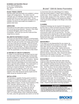
The analyzer flow system is shown schematically in Figure 2-1. It
includes a needle valve for adjusting the sample flow rate, a flowmeter to
indicate the sample flow required for calibration, the humidifier, the measur-
ing cell, and an automatic level control system for the water in the humidi-
fier.
As can be seen from Figure 2-1, the sample enters the humidifier
column against the pressure of a water column from the base of the humidi-
fier to the water level in the reservoir, which is approximately 4 inches.
This determines the minimum sample pressure at which any sample can flow
through the analyzer. In practice, the sample pressure must be somewhat
greater than this in order to have an adequate flow rate.
The automatic level control in the humidifier column is accomplished
by connecting the sample outflow from the cell to the bottom of the reser-

2-3
TT
TT
T
race Oxygrace Oxyg
race Oxygrace Oxyg
race Oxyg
en Analen Anal
en Analen Anal
en Anal
yzyz
yzyz
yz
erer
erer
er
Operational Theory 2Operational Theory 2
Operational Theory 2Operational Theory 2
Operational Theory 2
Teledyne Analytical Instruments
Figure 2-1: Flow System Schematic
Cell
Pressure
ATM + (b - a)
b - a
b
a
Vent
Reservoir
Drain
Throttle
Valve
Flowmeter
Humidifier
Column
Water
Sample In
Cell Compartment

2-4
2 Operational Theory2 Operational Theory
2 Operational Theory2 Operational Theory
2 Operational Theory
Model 356WModel 356W
Model 356WModel 356W
Model 356W
AA
AA
A
Teledyne Analytical Instruments
voir. This places a back pressure on the sample in the cell and upper portion
of the humidifier column equal to the water column from the bottom of the
reservoir to the water level in the reservoir. Thus, the water level in the
humidifier column is held even with the sample connection at the bottom of
the reservoir. There will be a slight additional pressure in the top of the
humidifier column depending on the flow rate (the pressure needed to push
the sample through the cell and associated tubing), but at normal flow rates
this merely slightly lowers the level in the humidifier column.
The sample bubbles through the water in the reservoir on its way to the
outlet port. Some of the water vapor will re-condense, so that the sample
flows out of the outlet port saturated at the reservoir temperature, which is
slightly above ambient. The sample bubbling through the make-up water
will scrub out any oxygen which may be dissolved in it. This assures that the
sample will not pick up any oxygen as it passes through the humidifier
column.

TT
TT
T
race Oxygrace Oxyg
race Oxygrace Oxyg
race Oxyg
en Analen Anal
en Analen Anal
en Anal
yzyz
yzyz
yz
erer
erer
er
Installation 3Installation 3
Installation 3Installation 3
Installation 3
3-1
Teledyne Analytical Instruments
InstallationInstallation
InstallationInstallation
Installation
3.1 Location3.1 Location
3.1 Location3.1 Location
3.1 Location
With proper shielding of the leads, the analyzer and the readout device
can be separated by as much as 1,000 feet. However, they should be placed
as close together as possible. For the most convenient operation, the read-
out recorder or meter should be within view of the controls, particularly
when the unit is being calibrated. Figure 2-1 depicts a typical system layout.
Other location considerations:
1) The analyzer should be sheltered from the elements.
2) Ambient temperature must be within
30 to 120 °F.30 to 120 °F.
30 to 120 °F.30 to 120 °F.
30 to 120 °F.
3) The unit should not be subject to excessive shock or vibration.
4) It should be as close as possible to the sample point.
5) There must be access to the back and side of the unit for
connection or maintenance of sample lines and power.
NOTE:NOTE:
NOTE:NOTE:
NOTE:
Since the level of the electrolyte in the measuring cell is critical andSince the level of the electrolyte in the measuring cell is critical and
Since the level of the electrolyte in the measuring cell is critical andSince the level of the electrolyte in the measuring cell is critical and
Since the level of the electrolyte in the measuring cell is critical and
the water level control system for the humidifier is gravity sensitive,the water level control system for the humidifier is gravity sensitive,
the water level control system for the humidifier is gravity sensitive,the water level control system for the humidifier is gravity sensitive,
the water level control system for the humidifier is gravity sensitive,
THE ANALYZER MUST BE MOUNTED SO THAT THE BOTTOM OFTHE ANALYZER MUST BE MOUNTED SO THAT THE BOTTOM OF
THE ANALYZER MUST BE MOUNTED SO THAT THE BOTTOM OFTHE ANALYZER MUST BE MOUNTED SO THAT THE BOTTOM OF
THE ANALYZER MUST BE MOUNTED SO THAT THE BOTTOM OF
THE CASE IS LEVEL.THE CASE IS LEVEL.
THE CASE IS LEVEL.THE CASE IS LEVEL.
THE CASE IS LEVEL.
3.2 Electrical Connections3.2 Electrical Connections
3.2 Electrical Connections3.2 Electrical Connections
3.2 Electrical Connections
A diagram of the necessary electrical connections is shown in Figure 2-2.
Note: Note:
Note: Note:
Note:
See the Interconnection Diagram (drawing A-37526) included in theSee the Interconnection Diagram (drawing A-37526) included in the
See the Interconnection Diagram (drawing A-37526) included in theSee the Interconnection Diagram (drawing A-37526) included in the
See the Interconnection Diagram (drawing A-37526) included in the
back of this manual, as well as any Addenda that may be includedback of this manual, as well as any Addenda that may be included
back of this manual, as well as any Addenda that may be includedback of this manual, as well as any Addenda that may be included
back of this manual, as well as any Addenda that may be included
with this manual for information specific to your instrument.with this manual for information specific to your instrument.
with this manual for information specific to your instrument.with this manual for information specific to your instrument.
with this manual for information specific to your instrument.

3-2
3 Installation3 Installation
3 Installation3 Installation
3 Installation
Model 356WModel 356W
Model 356WModel 356W
Model 356W
AA
AA
A
Teledyne Analytical Instruments
Figure 2-1 Typical System Layout
The connections include a terminal for grounding the analyzer case and
chassis in accordance with accepted industrial practices. The maximum
power requirement is less than
1½ amperes at 115 VAC1½ amperes at 115 VAC
1½ amperes at 115 VAC1½ amperes at 115 VAC
1½ amperes at 115 VAC.
3.3 Sample Connections3.3 Sample Connections
3.3 Sample Connections3.3 Sample Connections
3.3 Sample Connections
The sample line is connected at the back of the analyzer case as de-
picted in Figure 2-3. Use care in assembling any part of the sampling system
to avoid leaks. Oxygen can diffuse into the system through small leaks even
when sample pressure is much greater than atmospheric pressure. A
1
/8"
female NPT fitting is installed on the back of the instrument for making
sample and vent line connections. Thepurge line is fitted with a
1
/4" tube
fitting.
1.
ConnectorsConnectors
ConnectorsConnectors
Connectors. Use straight tube connectors where possible.
This facilitates removal of the analyzer section from the case
during maintenance or service.
2.
LinesLines
LinesLines
Lines. Lines should consist of metallic tubing, since oxygen can
diffuse through plastic. Use continuous tubing where possible.
3.
VentVent
VentVent
Vent. The analyzed sample is vented through the back of the
unit as shown in Figure 2-3.
Sample
Line
Sample Line
(1/4" or 1/8" Metal Tubing)
Shut Off
Valve
Pressure
Regulator
(5-10 psig Output)
Vent
Condensate Trap
1/4"
Tub ing
Signal Leads
(22 ga. Twisted
Pair Shielded
Cable)
Percent Oxygen
Analyzer
Recorder
115 VAC Power and Ground
2 Power Leads
1 Ground Wire
(16 ga. Insulated)
Vent
Sample
In

TT
TT
T
race Oxygrace Oxyg
race Oxygrace Oxyg
race Oxyg
en Analen Anal
en Analen Anal
en Anal
yzyz
yzyz
yz
erer
erer
er
Installation 3Installation 3
Installation 3Installation 3
Installation 3
3-3
Teledyne Analytical Instruments
The analyzer should have a vent line of ¼" diameter tubing at least two
feet long, running
downwarddownward
downwarddownward
downward from the vent connection. This is to prevent
air from diffusing into the reservoir and dissolving into the humidifier make-
up water.
If it is not desirable to vent the sample into the atmosphere, a vent line
to carry the sample to a suitable venting area will be required. The sample
leaves the vent connection of the analyzer saturated with water vapor at a
temperature somewhat above ambient, so a suitable trap to remove conden-
sate without plugging the vent line will be required. The vent line should
also be arranged so that it cannot become plugged by dirt or dust.
Figure 2-2: General Connection Diagram
See the specific Interconnection Diagram for your instrument in the drawing
package located at the back of the manual. See also any Addenda that may be
included with this manual.
TS 1
1 2 3 4 5 6 7 8 9 10 11 12 13 14
GND
mV
Output
Current
Output
HOT
NEUT
GND
NO
C
NC
NO
C
NC
AC Power In
150 Watt Max
Load
Alarm 2
Alarm 1

3-4
3 Installation3 Installation
3 Installation3 Installation
3 Installation
Model 356WModel 356W
Model 356WModel 356W
Model 356W
AA
AA
A
Teledyne Analytical Instruments
Figure 5: Gas Connections to Back of Analyzer
18-1/4"
17-9/16"
2"
15"
7-15/16"
17"
9"
5/16"
Sample
Purge
Vent
115 V 50/60 Hz
Power In
Signal Out
1/4" Female NPT
7/8" dia. holes
for 1/2" conduit
FIGURE 5 ANALYZER OUTLINE DIAGRAM

4-1
TT
TT
T
race Oxygrace Oxyg
race Oxygrace Oxyg
race Oxyg
en Analen Anal
en Analen Anal
en Anal
yzyz
yzyz
yz
erer
erer
er
Operations 4Operations 4
Operations 4Operations 4
Operations 4
Teledyne Analytical Instruments
OperationsOperations
OperationsOperations
Operations
4.14.1
4.14.1
4.1
Filling the ReservoirFilling the Reservoir
Filling the ReservoirFilling the Reservoir
Filling the Reservoir
The reservoir is located on the right side of the analyzer case.
1) Insure that the cap on the drain spout is securely tightened.
2) Remove cap from fill port on top of reservoir.
3) Pour distilled water into reservoir until it is half full (about one
quart). The water will automatically flow into the humidifier
column.
4) Replace cap on fill port and securely tighten. A missing or loose
cap will permit the sample to vent into the analyzer case.
4.24.2
4.24.2
4.2
Detector CellDetector Cell
Detector CellDetector Cell
Detector Cell
The cell is located in the heated compartment on the left side of the
analyzer case, as shown in Figure 4-1. To open the compartment, unscrew
the captive knurled knobs at the top and bottom of the compartment and
remove the plastic window.
4.2.14.2.1
4.2.14.2.1
4.2.1
Cell PackagingCell Packaging
Cell PackagingCell Packaging
Cell Packaging
The cell is packaged separately from the analyzer. It is filled with
distilled water to prevent oxidation of the electrodes from exposure to the
atmosphere. The cell should be left filled with the distilled water until the
analyzer is installed and ready for operation. The cell should not be exposed
to the atmosphere for any prolonged duration.
4.2.24.2.2
4.2.24.2.2
4.2.2
ElectrolyteElectrolyte
ElectrolyteElectrolyte
Electrolyte
The cell electrolyte is Teledyne Type A, used in applications where
there is a complete absence of acidic anhydrides (CO
2
, SO
2
) in the sample
gas. Type A electrolyte is a 10% solution (w/v) of reagent-grade potassium
hydroxide (KOH) in distilled water.

4-2
4 Operations4 Operations
4 Operations4 Operations
4 Operations
Model 356WModel 356W
Model 356WModel 356W
Model 356W
AA
AA
A
Teledyne Analytical Instruments
Figure 4-1: Typical Model 306WA With 2 Alarm Option
WARNING:
Type A electrolyte is caustic. Use extreme care in
handling. Protective equipment including but not
limited to gloves and safety glasses should be worn
while handling electrolyte. Refer to the Material Safety
Data Sheet in the Appendix regarding potential hazards
and corrective action in case of accident.
Type B electrolyte is a 20 % solution (w/v) of potassium carbonate and
should be used when the CO
2
level in the background gas is between 500
ppm and 1 %. This narrow range is rarely encountered. It is, however
available from the factory. Safety related information for this electrolyte can
be found in the Appendix.
Type C electrolyte is a 20 % solution (w/v) of potassium bicarbonate
and should be used when the CO
2
level in the background gas is between 1
and 100 %. Safety related information for this electrolyte can be found in
the Appendix.
Span
1
2
3
Range
10
20
30
Humidifier
Control
Current Adj
Alarm 1
2 Amp
Alarm 2
1 2 3 4 5
Control Assembly
Interconnect
Terminal Strip
Heater
Cell Compartment Terminal Strip
Cell
Assembly
Heater
Flowmeter
Humidifier
Column
Assembly
Sample
System
Assembly
Sample
System
Assembly
with
Reservoir
Throttle
Valve

4-3
TT
TT
T
race Oxygrace Oxyg
race Oxygrace Oxyg
race Oxyg
en Analen Anal
en Analen Anal
en Anal
yzyz
yzyz
yz
erer
erer
er
Operations 4Operations 4
Operations 4Operations 4
Operations 4
Teledyne Analytical Instruments
Sufficient electrolyte is provided for initial servicing of the cell. Elec-
trolyte for future service should be ordered from Teledyne. When ordering,
specify type and quantity.
4.2.34.2.3
4.2.34.2.3
4.2.3
Cell InstallationCell Installation
Cell InstallationCell Installation
Cell Installation
Prior to servicing and installing the cell, inspect the lead electrode in
the acrylic base for signs of oxidation, indicated by a reddish-brown or
yellow discoloration. If discoloration is noted, clean the cell as directed in
section 5.5.2 before placing it in service.
WARNING: Type A electrolyte is caustic. Use extreme care in
handling. Protective equipment including but not
limited to gloves and safety glasses should be worn
while handling electrolyte. Refer to the Material Safety
Data Sheet in the Appendix regarding potential hazards
and corrective action in case of accident.
1) Remove the four cell mounting bolts which secure the plastic
cover. Pour out the distilled water.
2) Pour about half the furnished electrolyte into the cell and slosh
until all components within the cell are wetted by the solution.
Drain and dispose of the solution.
3) Wipe the top of the cell and the O-ring with a clean, disposable
tissue to remove solution from the exterior.
DO NOTDO NOT
DO NOTDO NOT
DO NOT touch the
interior of the cell.
4) Carefully pour in electrolyte until it just touches the bottom edge
of the silver screen assembly at all points. This is indicated by a
definite wicking of electrolyte onto the screen assembly at every
point along ithe bottom edge. It is essential at this point that the
bottom edge of the screen assembly be wetted at all points (as
seen by the wicking action), but not over-immersed (as large a
surface area as possible of the screen assembly must remain
above the electrolyte, while every point of the bottom edge must
be wetted). The level is correct when the bottom edge of the
sensor screen is wetted but not immersed; approximately
3
/32 "of
the silver electrode extends into the pool of eelectrolyte.
NOTE:The electrolyte level in the cell is critically related to its sensitivity
due to the change in the cathode surface area exposed to the
eledctrolyte.
5) Carefully place the cell under the cell mounting plate with the
outer terminal toward the front. Secure in place with four bolts
supplied with the cell. Refer to Figure 4-2.

4-4
4 Operations4 Operations
4 Operations4 Operations
4 Operations
Model 356WModel 356W
Model 356WModel 356W
Model 356W
AA
AA
A
Teledyne Analytical Instruments
Figure 4-2: Cell Compartment Components
Humidifier Column Heater
Humidifier Column
Cell Block
Sample Flow
Control Valve
Cell Mounting
Bolts
Terminal Strip
No. 4
Flowmeter
O-Ring

4-5
TT
TT
T
race Oxygrace Oxyg
race Oxygrace Oxyg
race Oxyg
en Analen Anal
en Analen Anal
en Anal
yzyz
yzyz
yz
erer
erer
er
Operations 4Operations 4
Operations 4Operations 4
Operations 4
Teledyne Analytical Instruments
6) Connect the red lead to the center terminal and the black lead to
the outer terminal.
NOTE:The silver screens in the cell have been specially treated to pro-
vide proper detection characteristics. They must be kept clean and
MUST NOT be touched. Even clean fingers secrete natural oils
which contaminate the screens. If the screens need straightening,
wash a small pair of tweezers thoroughly to remove any grease,
rinse them in distilled water, and use them to carefully bend the
screens back into place.
4.34.3
4.34.3
4.3
Throttle ValveThrottle Valve
Throttle ValveThrottle Valve
Throttle Valve
The throttle valve is located at the top of the reservoir tank. Refer to
Figure 4-1.
1) Gently turn the valve counterclockwise. A stream of bubbles
should appear at the base of the humidifier column, and the float
of the flowmeter should rise in its tube.
2) Adjust the valve so that the flowmeter float is centered in the
flow rate reference indicator.
CAUTION: Open the throttle valve carefully. Excessive flow rate
may cause water in the humidifier column to be carried
into the detector cell. This can cause erratic readings
and may require disassembly, cleaning, and refilling of
the sensor
.
3) The flowmeter indicator has been factory set to a flow rate of
150 cc/min150 cc/min
150 cc/min150 cc/min
150 cc/min. for the specified sample gas.
CAUTION: Excessive flow rate may cause water in the humidifier
to be carried to the flowmeter causing moisture to
accumulate. This can cause the ball to stick in the
flowmeter. To remove moisture, remove the flowmeter
and allow to air or blow dry. Refer to the detailed in-
structions in Figure 5-2 for removal and installation of
the column.
4.44.4
4.44.4
4.4
Humidity ControlHumidity Control
Humidity ControlHumidity Control
Humidity Control
The humidity control is located on the front panel of the control unit,
and is adjusted to maintain a constant electrolyte level in the detector cell.
In effect, the control governs the humidity of the sample which is directed
to the cell.

4-6
4 Operations4 Operations
4 Operations4 Operations
4 Operations
Model 356WModel 356W
Model 356WModel 356W
Model 356W
AA
AA
A
Teledyne Analytical Instruments
Figure 8: Calibrator Assembly
Electrical Terminal Board
Sub-Assembly
O-Ring
Outside Electrode Connected to
"Y" Terminal Post (+)
Oxygen Generated Here
Wick Saturated With KOH
Electrolyte Solution
Inside Electrode Connected
to "B" Terminal Post (-)
Hydrogen Generated Here
/