Philips BDL5586XH User manual
- Category
- Public displays
- Type
- User manual

www.philips.com/welcome
BDL5586XH
User Manual (English)

BDL5586XH
ii
Safety Instructions
Safety precautions and maintenance
WARNING: Use of controls, adjustments or procedures other than those specied in this documentation may result in exposure to
shock, electrical hazards and/or mechanical hazards.
Operation:
Keep the display out of direct sunlight and away from stoves or any other heat sources.
Remove any object that could fall into ventilation holes or prevent proper cooling of the display’s electronics.
Do not block the ventilation holes on the cabinet.
When positioning the display, make sure the power plug and outlet are easily accessible.
When turning off the display by detaching the power cord, wait 6 seconds before re-attaching the power cord for normal operation.
Ensure the use of an approved power cord provided by Philips at all times. If your power cord is missing, please contact your local service center.
Do not subject the display to severe vibration or high impact conditions during operation.
Do not knock or drop the display during operation or transportation.
Maintenance:
• To protect your display from possible damage, do not put excessive pressure on the LCD panel. When moving your display, grasp the frame to lift; do
not lift the display by placing your hand or ngers on the LCD panel.
• Unplug the display if you are not going to use it for an extensive period of time.
• Unplug the display if you need to clean it with a slightly damp cloth. The screen may be wiped with a dry cloth when the power is off. However, never
use organic solvent, such as, alcohol, or ammonia-based liquids to clean your display.
• To avoid the risk of shock or permanent damage to the set, do not expose the display to dust, rain, water or an excessively moist environment.
• If your display becomes wet, wipe it with dry cloth as soon as possible.
• If a foreign substance or water gets in your display, turn the power off immediately and disconnect the power cord. Then remove the foreign substance
or water, and send the unit to the maintenance center.
• Do not store or use the display in locations exposed to heat, direct sunlight or extreme cold.
• In order to maintain the best performance of your display and ensure a longer lifetime, we strongly recommend using the display in a location that falls
within the following temperature and humidity ranges.
- Temperature: 0-40°C 32-104°F
- Humidity: 20-80% RH
IMPORTANT: Always activate a moving screen saver program when you leave your display unattended. Always activate a periodic screen refresh
application if the unit will display unchanging static content. Uninterrupted display of still or static images over an extended period may cause “burn in”,
also known as “after-imaging” or “ghost imaging”, on your screen. This is a well-known phenomenon in LCD panel technology. In most cases, the “burned
in” or “after-imaging” or “ghost imaging” will disappear gradually over a period of time after the power has been switched off.
WARNING: Severe “burn-in” or “after-image” or “ghost image” symptoms will not disappear and cannot be repaired. This is also not covered under the
terms of your warranty.
Service:
• The casing cover should be opened only by qualied service personnel.
• If there is any need for repair or integration, please contact your local service center.
• Do not leave your display under direct sunlight.
If your display does not operate normally, having followed the instructions set out in this document, please contact a technician or your
local service center..

BDL5586XH
iii
Read and follow these instructions when connecting and using your display:
• Unplug the display if you are not going to use it for an extensive period of time.
• Unplug the display if you need to clean it with a slightly damp cloth. The screen many be wiped with a dry cloth when the power is
off. However, never use alcohol, solvents or ammonia-based liquids.
• Consult a service technician if the display does not operate normally when you have followed the instructions in this manual.
• The casing cover should be opened only by qualied service personnel.
• Keep the display out of direct sunlight and away from stoves or any other heat sources.
• Remove any object that could fall into the vents or prevent proper cooling of the display’s electronics.
• Do not block the ventilation holes on the cabinet.
• Keep the display dry. To avoid electric shock, do not expose it to rain or excessive moisture.
• When turning off the display by detaching the power cable or DC power cord, wait for 6 seconds before re-attaching the power
cable or DC power cord for normal operation..
• To avoid the risk of shock or permanent damage to the set do not expose the display to rain or excessive moisture.
• When positioning the display, make sure the power plug and outlet are easily accessible.
• IMPORTANT: Always activate a screen saver program during your application. If a still image in high contrast remains on the
screen for an extended period of time, it may leave an ‘after-image’ or ‘ghost image’ on the front of the screen. This is a well-known
phenomenon that is caused by the shortcomings inherent in LCD technology. In most cases the afterimage will disappear gradually
over a period of time after the power has been switched off. Be aware that the after-image symptom cannot be repaired and is not
covered under warranty.

BDL5586XH
iv
Regulatory Information
CE Declaration of Conformity
We declare under our responsibility that the product is in conformity with the following standards:
• EN60950-1:2006+A11:2009+A1:2010+A12:2011 (Safety requirement of Information Technology Equipment).
• EN55022:2010 (Radio Disturbance requirement of Information Technology Equipment).
• EN55024:2010 (Immunity requirement of Information Technology Equipment).
• EN61000-3-2:2006 +A1:2009+A2:2009 (Limits for Harmonic Current Emission).
• EN61000-3-3:2008 (Limitation of Voltage Fluctuation and Flicker)
• EN 50581:2012 (Technical documentation for the assessment of electrical and electronic products with respect to the restriction of hazardous
substances)
following provisions of directives applicable.
• 2006/95/EC (Low Voltage Directive).
• 2004/108/EC (EMC Directive).
• 2009/125/EC (ErP, Energy-related Product Directive, EC No. 1275/2008 and 642/2009 Implementing)
• 2011/65/EU (RoHS Directive) and is produced by a manufacturing organization on ISO9000 level.
Federal Communications Commission (FCC) Notice (U.S. Only)
This equipment has been tested and found to comply with the limits for a Class B digital device, pursuant to Part 15 of the FCC
Rules. These limits are designed to provide reasonable protection against harmful interference when the equipment is operated in
a commercial environment. This equipment generates, uses and can radiate radio frequency energy and, if not installed and used in
accordance with the instructions manual, may cause harmful interference to radio communications. Operation of this equipment in
a residential area is likely to cause harmful interference in which case the user will be required to correct the interference at his own
expense.
Changes or modications not expressly approved by the party responsible for compliance could void the user’s authority to operate the
equipment.
Use only an RF shielded cable that was supplied with the display when connecting this display to a computer device.
To prevent damage which may result in re or shock hazard, do not expose this appliance to rain or excessive moisture.
THIS CLASS B DIGITAL APPARATUS MEETS ALL REQUIREMENTS OF THE CANADIAN INTERFERENCE- CAUSING EQUIPMENT REGULATIONS.
This device complies with Part 15 of the FCC Rules. Operation is subject to the following two conditions: (1) this device may not
cause harmful interference, and (2) this device must accept any interference received, including interference that may cause undesired
operation.

BDL5586XH
v
Polish Center for Testing and Certication Notice
The equipment should draw power from a socket with an attached protection circuit (a three-prong socket). All equipment that works together (computer,
display, printer, and so on) should have the same power supply source.
The phasing conductor of the room’s electrical installation should have a reserve short-circuit protection device in the form of a fuse with a nominal value
no larger than 16 amperes (A).
To completely switch off the equipment, the power supply cable must be removed from the power supply socket, which should be located near the
equipment and easily accessible.
A protection mark “B” conrms that the equipment is in compliance with the protection usage requirements of standards PN-93/T-42107 and PN-89/
E-06251.
Electric, Magnetic and Electronmagnetic Fields (“EMF”)
1. We manufacture and sell many products targeted at consumers, which, like any electronic apparatus, in general have the ability to emit and receive
electromagnetic signals.
2. One of our leading Business Principles is to take all necessary health and safety measures for our products, to comply with all applicable legal
requirements and to stay well within the EMF standards applicable at the time of producing the products.
3. We are committed to develop, produce and market products that cause no adverse health effects.
4. We conrm that if its products are handled properly for their intended use, they are safe to use according to scientic evidence available today.
5. We play an active role in the development of international EMF and safety standards, enabling us to anticipate further developments in standardization
for early integration in its products.

BDL5586XH
vi
Information for U.K. only
(A)
(B)
WARNING - THIS APPLIANCE MUST BE EARTHED.
Important:
This apparatus is supplied with an approved moulded 13A plug. To change a fuse in this type of plug
proceed as follows:
1. Remove fuse cover and fuse.
2. Fit new fuse which should be a BS 1362 5A,A.S.T.A. or BSI approved type.
3. Ret the fuse cover.
If the tted plug is not suitable for your socket outlets, it should be cut off and an appropriate 3-pin
plug tted in its place.
If the mains plug contains a fuse, this should have a value of 5A. If a plug without a fuse is used, the fuse
at the distribution board should not be greater than 5A.
NOTE: The severed plug must be destroyed to avoid a possible shock hazard should it be inserted
into a 13A socket elsewhere.
How to connect a plug
The wires in the mains lead are coloured in accordance with the following code:
BLUE - “NEUTRAL” (“N”)
BROWN - “LIVE” (“L”)
GREEN & YELLOW - “EARTH” (“E”)
1. The GREEN & YELLOW wire must be connected to the terminal in the plug which is marked with
the letter “E” or by the Earth symbol or coloured GREEN or GREEN & YELLOW.
2. The BLUE wire must be connected to the terminal which is marked with the letter “N” or coloured
BLACK.
3. The BROWN wire must be connected to the terminal which marked with the letter “L” or
coloured RED.
Before replacing the plug cover, make certain that the cord grip is clamped over the sheath of the lead
- not simply over the three wires.

BDL5586XH
vii
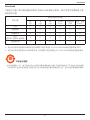
China RoHS
中国电子信息产品污染控制标识要求 (中国RoHS法规标示要求) 产品中有毒有害物质或元素
的名称及含量
部件名称
有毒有害物质或元素
铅
(Pb)
汞
(Hg)
镉
(Cd)
六价铬
(Cr 6+)
多溴联苯
(PBB)
多溴二苯醚
(PBDE)
外壳 O O O O O O
液晶面板 X O O O O O
电路板组件 X O O O O O
附件
(遥控器,电源线,连接线)
X O O O O O
遥控器电池 X O O O O O
O: 表示该有毒有害物质在该部件所有均质材料中的含量均在 SJ/T11363-2006 标准规定的限量要求以下.
X: 表示该有毒有害物质至少在该部件的某一均质材料中的含量超出 SJ/ T11363-2006 标准规定的限量要求.
10
環保使用期限
此標識指期限(十年),電子信息產品中含有的有毒有害物質或元素在正常使用的條件下不會發生外泄或突變
,電子信息產品用戶使用該電子信息產品不會對環境造成嚴重污染或對其人身、財產造成嚴重損害的期限。

BDL5586XH
viii
North Europe (Nordic Countries) Information
Placering/Ventilation
VARNING:
FÖRSÄKRA DIG OM ATT HUVUDBRYTARE OCH UTTAG ÄR LÄTÅTKOMLIGA, NÄR DU STÄLLER DIN UTRUSTNING PÅPLATS.
Placering/Ventilation
ADVARSEL:
SØRG VED PLACERINGEN FOR, AT NETLEDNINGENS STIK OG STIKKONTAKT ER NEMT TILGÆNGELIGE.
Paikka/Ilmankierto
VAROITUS:
SIJOITA LAITE SITEN, ETTÄ VERKKOJOHTO VOIDAAN TARVITTAESSA HELPOSTI IRROTTAA PISTORASIASTA.
Plassering/Ventilasjon
ADVARSEL:
NÅR DETTE UTSTYRET PLASSERES, MÅ DU PASSE PÅ AT KONTAKTENE FOR STØMTILFØRSEL ER LETTE Å NÅ.
End-of-Life Disposal
Your new Public Information Display contains materials that can be recycled and reused. Specialized companies can recycle your product to increase the
amount of reusable materials and to minimize the amount to be disposed of.
Please nd out about the local regulations on how to dispose of your old display from your local Philips dealer.
(For customers in Canada and U.S.A.)
This product may contain lead and/or mercury. Dispose of in accordance to local-state and federal regulations. For additional information on recycling
contact www.eia.org (Consumer Education Initiative)
Waste Electrical and Electronie Equipment-WEEE
Attention users in European Union private households
This marking on the product or on its packaging illustrates that, under European Directive
2012/19/EU
governing used electrical and
electronic appliances, this product may not be disposed of with normal household waste. You are responsible for disposal of this
equipment through a designated waste electrical and electronic equipment collection. To determine the locations for dropping off such
waste electrical and electronic, contact your local government ofce, the waste disposal organization that serves your household or the
store at which you purchased the product.
Attention users in United States:
Please dispose of according to all Local, State and Federal Laws. For the disposal or recycling information, contact: www.mygreenelectronics.com or www.
eiae.org.
End of Life Directives-Recycling
Your new Public Information Display contains several materials that can be recycled for new users.
Please dispose of according to all Local, State, and Federal laws.

BDL5586XH
ix
Table Of Contents
3.5. Connecting Multiple Displays in a Daisy-
chain Conguration .............................................. 16
3.5.1. Display control connection ..............16
3.5.2. Digital video connection ....................16
3.5.3. Analog video connection ..................16
3.5.4. IR daisy-chain Connection ................17
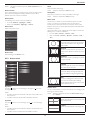
4. OSD Menu ..............................................................18
4.1. Navigating the OSD Menu ............................. 18
4.1.1. Navigating the OSD menu using the
remote control........................................18
4.1.2. Navigating the OSD menu using the
display’s control buttons ....................18
4.2. OSD Menu Overview ........................................ 18
4.2.1. Picture menu ............................................18
4.2.2. Screen menu ............................................19
4.2.3. Audio menu ..............................................20
4.2.4. PIP menu ....................................................20
4.2.5. Conguration1 menu ..........................21
4.2.6. Conguration2 menu ..........................22
4.2.7. Advanced option menu .....................22
5. Input Mode ..............................................................27
6. Pixel Defect Policy .................................................28
6.1. Pixels and Sub-Pixels ............................................28
6.2. Types of Pixel Defects + Dot Denition . 28
6.3. Bright Dot Defects ...............................................28
6.4. Dark Dot Defects .................................................29
6.5. Proximity of Pixel Defects ................................ 29
6.6. Pixel Defect Tolerances ......................................29
6.7. MURA .......................................................................... 29
7. Cleaning and Troubleshooting .............................30
7.1. Cleaning ......................................................................30
7.2. Troubleshooting ......................................................31
8. TechnicalSpecications ........................................32
1. Unpacking and Installation ..................................... 1
1.1. Unpacking .....................................................................1
1.2. Package Contents ..................................................... 1
1.3. Installation Notes ...................................................... 1
1.4. Installing and Removing Table Stands
(optional) .......................................................................2
1.5. Mounting on a Wall ................................................. 3
1.5.1. VESA Grid ....................................................3
1.6. Mounting in Portrait Position .............................4
1.7. Operating Instructions of Edge Alignment
Kit / Pin ...........................................................................4
1.7.1. Installing Edge Alignment Pin .............5
1.7.2. Installing Edge Alignment Kit ..............5
2. Parts and Functions ................................................. 7
2.1. Control Panel .............................................................. 7
2.2. Input/Output Terminals .........................................8
2.3. Remote Control ........................................................ 9
2.3.1. General functions .....................................9
2.3.2. Inserting the batteries in the remote
control..........................................................10
2.3.3. Handling the remote control ..........10
2.3.4. Operating range of the remote
control..........................................................10
3. Connecting External Equipment ........................11
3.1. Connecting External Equipment (DVD/
VCR/VCD) ................................................................11
3.1.1. Using COMPONENT video
input ..............................................................11
3.1.2. Using Video Source input ..................11
3.1.3. Using HDMI video input ...................12
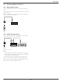
3.2. Connecting a PC ....................................................12
3.2.1. Using VGA input .....................................12
3.2.2. Using DVI input ......................................13
3.2.3. Using HDMI input ................................. 13
3.2.4. Using DisplayPort input .....................14
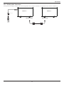
3.3. Connecting Audio Equipment ........................14
3.3.1. Connecting external speakers........14
3.3.2. Connecting an external audio
device ...........................................................14
3.4. Connecting Remote Control ..........................15
3.4.1. Single Display Control .......................15
3.4.2. IR Pass Through Control .................. 15

BDL5586XH
1
1. Unpacking and Installation
1.1. Unpacking
• This product is packed in a carton, together with the standard accessories.
• Any other optional accessories will be packed separately.
• Due to the size and weight of this display it is recommended for two people to move it.
• After opening the carton, ensure that the contents are complete and in good condition.
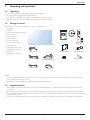
1.2. Package Contents
Please verify that you received the following items with your package content:
• LCD display
• CD ROM
• Remote control with AAA batteries
• Power cord (1.8 m)
• VGA cable (1.8 m)
• RS232 cable (3 m)
• IR sensor cable(1.8m)
• 3.5mm Jack IR cable(1.8m)
• Quick start guide
• Edge Alignment Kit-1: 1PCS
• Edge Alignment Kit-2: 2PCS
• Screw: 8PCS
• Edge Alignment Pin: 2PCS
* The supplied power cord varies depending on destination.
Power Cord
Video Signal Cable
(D-SUB to D-SUB Cable)
RS232 Cable
POWER
SMART
VIDEO
SOURCE
PIP
INPUTON/OFF CHANGE
BRIGHTNESSCONTRAST
DISPLAY
AUTO
ADJUST
MUTE
VOL UP
VOL DOWN
EXIT
MENU
SET
AUDIO
SOURCE
USB MENU
Remote Control
and AAA Batteries
CD ROM
Register your product and get support at
www.philips.com/welcome
LCD-Display / Pantalla LCD / Écran LCD / Display LCD
Wyświetlacz LCD / ЖК-монитор / LCD Ekran / 液晶显示器 /
液晶顯示器
Kurzanleitung / Guía rápida / Guide de démarrage rapide / Guida rapida /
Instrukcja szybkiego uruchomienia / Краткое руководство по запуску /
Hızlı bașlangiç kılavuzu / 快速入门指南 /
快速入門指南
Installation / Installation / Instalación / Installation / Installazione / Instalacja /
Установка / Kurulum / 安装 /
安裝
Connect / Verbindungsfähigkeit / Conectividad / Connectivité / Connettività /
Połączenia / Подключение / Bağlantı / 连接性 /
連接性
BDL5586XH
LCD Display
Quick start guide
IR Sensor Cable
IR Cable
Edge Alignment Kit-1
Edge Alignment Kit-2
Edge Alignment Pin
Screw
NOTES:
• For all other regions, apply a power cord that conforms to the AC voltage of the power socket and has been approved by and complies with the
safety regulations of the particular country.
• You might like to save the package box and packing material for shipping the display.
1.3. Installation Notes
• Due to the high power consumption, always use the plug exclusively designed for this product. If an extended line is required, please consult your
service agent.
• The product should be installed on a at surface to avoid tipping. The distance between the back of the product and the wall should be maintained
for proper ventilation. Avoid installing the product in the kitchen, bathroom or any other places with high humidity so as not to shorten the service life
of the electronic components.
• The product can normally operate only under 3000m in altitude. In installations at altitudes above 3000m, some abnormalities may be experienced.

BDL5586XH
2
1.4. Installing and Removing Table Stands (optional)
To install table stands:
1. Ensure your display is powered off.
2. Spread a protective sheet on a at surface.
3. Grab the carrying handles and place the display face-down on the protective sheet.
4. After inserting the stand in the guide block, tighten the screws on both sides of the display.
NOTE: The longer side of the stand should face the front of the display.
Carrying handle
Table stand
Longer portions face to front
Thumbscrews
To remove table stands:
1. Power off the display.
2. Spread a protective sheet on a at surface.
3. Grab the carrying handles and place the display face-down on the protective sheet.
4. Remove screws using a screwdriver and place them in a safe place for reuse.

BDL5586XH
3
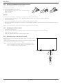
1.5. Mounting on a Wall
To mount this display to a wall, you will have to obtain a standard wall-mounting kit (commercially available). We recommend using a mounting interface
that complies with TUV-GS and/or UL1678 standard in North America.
Protective Sheet
VESA Grid
Tabletop standTable
~
1. Lay a protective sheet on a table, which was wrapped around the display when it was packaged, beneath the screen surface so as not to scratch the
screen face.
2. Ensure you have all accessories for mounting this display (wall mount, ceiling mount, table stand, etc).
3. Follow the instructions that come with the base mounting kit. Failure to follow correct mounting procedures could result in damage to the equipment
or injury to the user or installer. Product warranty does not cover damage caused by improper installation.
4. For the wall-mounting kit, use M6 mounting screws (having a length 10 mm longer than the thickness of the mounting bracket) and tighten them
securely.
1.5.1. VESA Grid
BDL5586XH
400(H) x 400(V) mm
Caution:
To prevent the display from falling:
• For wall or ceiling installation, we recommend installing the display with metal brackets which are commercially available. For detailed installation
instructions, refer to the guide received with the respective bracket.
• To lessen the probability of injury and damage resulting from fall of the display in case of earthquake or other natural disaster, be sure to consult the
bracket manufacturer for installation location.
Ventilation Requirements for enclosure locating
To allow heat to disperse, leave space between surrounding objects as shown in the
diagram below.
100 mm 100 mm
100 mm
100 mm

BDL5586XH
4
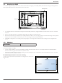
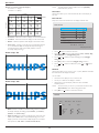
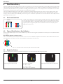
1.6. Mounting in Portrait Position
This display can be installed in portrait position.
1. Remove the table stand, if attached.
2. Rotate 90 degrees anticlockwise. The “ ” logo should be bristling when facing the display at the back.
90
90
1.7. Operating Instructions of Edge Alignment Kit / Pin

BDL5586XH
5
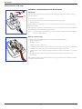
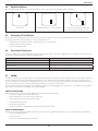
1.7.1. Installing Edge Alignment Pin
• During mounting displays to video wall frame, use “Edge Alignment Pin” to secure the atness of adjacent displays.
• Don’t let edge alignment pin to touch the side surface of panel, panel will damage due to incorrect installation.
• Using “Edge Alignment Pin” on adjacent displays.
There are 8 holes on the four corners of displays designed for plug-in the edge alignment pin.
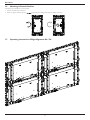
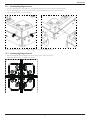
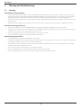
1.7.2. Installing Edge Alignment Kit
• Before install edge alignment kit, displays must be mounted to video wall frame correctly.
• Using “Edge Alignment Kit-1” on adjacent four displays.

BDL5586XH
6
Install “Edge Alignment Kit-1” with 8 PCS of screw on outer, bigger holes.
1
2
3
4
5
6
7
8
Using “Edge Alignment Kit-2” on adjacent two displays.
Install “Edge Alignment Kit-2” with 4 PCS of screw on outer, bigger holes.
1
2 3
4

BDL5586XH
7
2. Parts and Functions
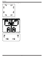
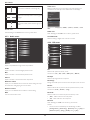
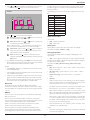
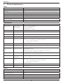
2.1. Control Panel
9
1 2 3 4 5 6 7 8
MUTE INPUT MENU
~
1
POWER button
Use this button to turn the display on or put the display to standby.
2
MUTE button
Switch the audio mute ON/OFF.
3
INPUT button
Use this button to select the input source.
4
[ ] button
Increase the adjustment while OSD menu is on, or increase the
audio output level while OSD menu is off.
5
[ ] button
Decrease the adjustment while OSD menu is on, or decrease the
audio output level while OSD menu is off.
6
[ ] button
Move the highlight bar up to adjust the selected item while OSD
menu is on.
7
[ ] button
Move the highlight bar down to adjust the selected item while OSD
menu is on.
8
MENU button
Return to previous menu while OSD menu is on, or to activate the
OSD menu when OSD menu is off.
NOTE: “Keyboard Control Lock Mode” This function completely
disables the access to all Keyboard Control functions. To
enable or disable the keyboard control lock, press both ]
and [ ] buttons and hold down continuously for more than
3 (three) seconds.
9
Remote control sensor and power status indicator
• Receives command signals from the remote control.
• Indicates the operating status of the display without OPS:
- Lights green when the display is turned on
- Lights red when the display is in standby mode
- Lights amber when the display enters APM mode
- When {SCHEDULE} is enabled, the light blinks green and red
- If the light blinks red, it indicates that a failure has been
detected
- Lights off when the main power of the display is turned off
• Indicates the operating status of the display with OPS:
- Lights green when the display is on, but the OPS is off
- Lights blue when the display and the OPS are on
- Lights red when the display is in standby mode
- Lights amber when the display enters APM mode
- When {SCHEDULE} is enabled, the light blinks green and red
- If the light blinks red, it indicates that a failure has been
detected
- Lights off when the main power of the display is turned off

BDL5586XH
8
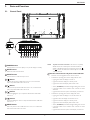
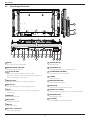
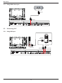
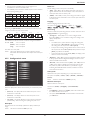
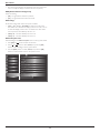
2.2. Input/Output Terminals
1
2 3
4
6 7
8
10
11
12 13
14
15
5
9
17
18
19
20
16
~
1
AC IN
AC power input from the wall outlet.
2
MAIN POWER SWITCH
Switch the main power on/off.
3
/
4
IR IN / IR OUT
Reserved for the wired connection of the IR control.
NOTE: If an external IR receiver is connected to [IR IN], there is no
function on the display’s remote sensor.
5
RS232C OUT:
RS232C network output for the loop-through function.
6
RS232C IN
RS232C network input for the loop-through function.
7
RJ-45
LAN control function for the use of remote control signal from
control center.
8
HDMI IN
HDMI video/audio input.
9
DisplayPort
DisplayPort video input.
10
DVI IN
DVI-D video input.
11
DVI OUT / VGA OUT
DVI or VGA video output.
12
VGA IN (D-Sub)
VGA video input.
13
VGA AUDIO IN
Audio input for VGA source (3.5mm stereo phone).
14
COMPONENT IN (BNC)
Component YPbPr video source input.
15
Y/CVBS
Video source input.
16
SPEAKER SWITCH
Internal speaker on/off switch.
17
AUDIO IN
Audio input from external AV device (RCA).
18
AUDIO OUT (RCA)
Audio output from the AUDIO IN jack to an external AV device.
19
SPEAKERS OUT
External speakers output.
20
OPS SLOT
Slot for installing the optional OPS module.

BDL5586XH
9
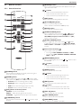
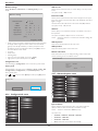
2.3. Remote Control
2.3.1. General functions
POWER
SMART
VIDEO
SOURCE
PIP
INPUTON/OFF CHANGE
BRIGHTNESSCONTRAST
DISPLAY
AUTO
ADJUST
MUTE
VOL UP
VOL DOWN
EXIT
MENU
SET
AUDIO
SOURCE
USB MENU
1
10
11
12
13
14
15
16
17
18
19
20
2
3
4
5
6
7
8
9
21
1
[POWER] button
Press to switch on the display from standby mode. Press again to
turn it off and back into standby mode.
2
[SMART] button
Press to activate Smart Menu. Press [ ] or [ ] button to select
menu options. Press [SET] button to conrm and exit the selection.
• Standard: Used for normal images (factory setting)
• Highbright: Used for moving image such as Video
• sRGB: Used for text based images(only for PC mode)
• Cinema: Used for movies(only for Video mode)
3
[PIP] (Picture In Picture) button
[ON/OFF]: Turn PIP mode ON/OFF.
[INPUT]: Select the input signal for the sub-picture.
[CHANGE]: Toggle between the main picture and sub picture.
4
[CONTRAST] button
Press to activate Contrast Menu. Press [ ] or [ ] button to adjust
the value.
5
[DISPLAY] button
Press to turn on/off the information OSD displayed on the upper
right corner of the screen.
6
[ ] button
• Press to move the selection left in OSD menu.
• Press to decrease the value in OSD menu.
• Press to move the sub-picture left in PIP mode.
7
[SET] button
Press to activate the setting inside the OSD menu.
8
[AUTO ADJUST] button
Press to run the Auto Adjust function.
NOTE: This button is functional for VGA input only.
9
[MUTE] button
Press to turn the mute function on/off.
10
[VIDEO SOURCE] button
Press to toggle Video Source Menu. Press [ ] or [ ] button to
select one of the video sources among Displayport, DVI-D,
VGA, HDMI, Component, Video, Card OPS. Press [SET]
button to conrm and exit.
11
[AUDIO SOURCE] button
Press to toggle Audio Source Menu. Press [ ] or [ ] button
to select one of the audio sources among Displayport, HDMI,
Audio1, Audio2 or Card OPS. Press [SET] button to conrm
and exit.
12
Picture Format button
Press to switch screen aspect ratio.
• For PC signal: FULL, NORMAL, CUSTOM, and REAL.
• For Video signal: FULL, NORMAL, DYNAMIC, CUSTOM,
REAL, and 21:9.
13
[BRIGHTNESS] button
Press to toggle Brightness Menu. Press [ ] or [ ] button to adjust
the value.tratrr
14
[ ] button
• Press to move the selection up in OSD menu.
• Press to move the sub-picture up in PIP mode.
15
[MENU] button
Press to turn the OSD menu on/off.
16
[ ] button
• Press to move the selection right in OSD menu.
• Press to increase the value in OSD menu.
• Press to move the sub-picture right in PIP mode.
17
[EXIT] button
Press to turn back to the previous OSD menu.
18
[ ] button
• Press to move the selection down in OSD menu.
• Press to move the sub-picture down in PIP mode.
19
[VOL UP] button
Press to increase the audio output level.
20
[VOL DOWN] button
Press to decrease the audio output level.
21
[USB MENU] button
This function is not available on this display.

BDL5586XH
10
2.3.2. Inserting the batteries in the remote control
The remote control is powered by two 1.5V AAA batteries.
To install or replace batteries:
1. Press and then slide the cover to open it.
2. Align the batteries according to the (+) and (–) indications inside the
battery compartment.
3. Replace the cover.
Caution:
The incorrect use of batteries can result in leaks or bursting. Be sure to follow these instructions:
• Place “AAA” batteries matching the (+) and (–) signs on each battery to the (+) and (–) signs of the battery compartment.
• Do not mix battery types.
• Do not combine new batteries with used ones. It causes shorter life or leakage of batteries.
• Remove the dead batteries immediately to prevent them from liquid leaking in the battery compartment. Don’t touch exposed battery acid, as it can
damage your skin.
NOTE: If you do not intend to use the remote control for a long period, remove the batteries.
2.3.3. Handling the remote control
• Do not subject to strong shock.
• Do not allow water or other liquid to splash the remote control. If the remote control gets wet, wipe it dry immediately.
• Avoid exposure to heat and steam.
• Other than to install the batteries, do not open the remote control.
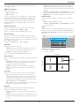
2.3.4. Operating range of the remote control
Point the top of the remote control toward the display’s remote control sensor when
pressing a button.
Use the remote control within a distance of less than 0.5m/2ft from the display’s sensor,
and a horizontal and vertical angle of less than 30 degrees.
NOTE: The remote control may not function properly when the remote control
sensor on the display is under direct sunlight or strong illumination, or when
there is an obstacle in the path of signal transmission.
30 30
POWER
SMART
VIDEO
SOURCE
PIP
INPUTON/OFF CHANGE
BRIGHTNESSCONTRAST
DISPLAY
AUTO
ADJUST
MUTE
VOL UP
VOL DOWN
EXIT
MENU
SET
AUDIO
SOURCE
USB MENU

BDL5586XH
11
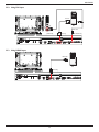
3. Connecting External Equipment
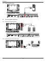
3.1. Connecting External Equipment (DVD/VCR/VCD)
3.1.1. Using COMPONENT video input
DVD / VCR / VCD
[AUDIO IN]
[COMPONENT IN]
(YPbPr)
COMPONENT Out
(YPbPr)
Audio Out
[R]
[L]
~
3.1.2. Using Video Source input
DVD / VCR / VCD
[AUDIO IN]
[Y/CVBS IN]
Y/CVBS Out
Audio Out
[R]
[L]
~
Page is loading ...
Page is loading ...
Page is loading ...
Page is loading ...
Page is loading ...
Page is loading ...
Page is loading ...
Page is loading ...
Page is loading ...
Page is loading ...
Page is loading ...
Page is loading ...
Page is loading ...
Page is loading ...
Page is loading ...
Page is loading ...
Page is loading ...
Page is loading ...
Page is loading ...
Page is loading ...
Page is loading ...
Page is loading ...
Page is loading ...
-
 1
1
-
 2
2
-
 3
3
-
 4
4
-
 5
5
-
 6
6
-
 7
7
-
 8
8
-
 9
9
-
 10
10
-
 11
11
-
 12
12
-
 13
13
-
 14
14
-
 15
15
-
 16
16
-
 17
17
-
 18
18
-
 19
19
-
 20
20
-
 21
21
-
 22
22
-
 23
23
-
 24
24
-
 25
25
-
 26
26
-
 27
27
-
 28
28
-
 29
29
-
 30
30
-
 31
31
-
 32
32
-
 33
33
-
 34
34
-
 35
35
-
 36
36
-
 37
37
-
 38
38
-
 39
39
-
 40
40
-
 41
41
-
 42
42
-
 43
43


Philips BDL5586XH User manual
- Category
- Public displays
- Type
- User manual
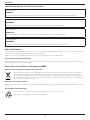
Ask a question and I''ll find the answer in the document
Finding information in a document is now easier with AI
Related papers
-
Philips E-Line Display BDL4652EL User manual
-
Philips HSB2313/12 User manual
-
-
-
Philips BDL4210Q User manual
-
-
-
-
-