Page is loading ...

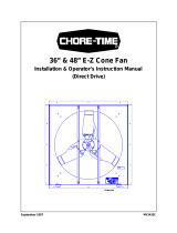
TURBO™
Fiberglass Cone Fan and Grill Fan
36'' Belt Drive
Installation & Operator’s Instruction Manual
MV1378BJune 1999

Chore-Time Warranty Turbo™ Fiberglass Cone Fan and Grill Fan 36'' Belt Drive
2 MV1378B
Chore-Time Equipment warrants new TURBO™ Fans and components manufactured by it to be free from
defects in material or workmanship from the date of initial installation by the original purchaser until expiration
of the appropriate period set forth below. If such a defect is found by Chore-Time to exist within the applicable
period, Chore-Time will, at its option, (a) repair or replace such product free of charge, F.O.B. the factory of
manufacture, or (b) refund to the original purchaser the original purchase price, in lieu of such repair or
replacement. The extended warranty is provided to the original purchaser for the following periods:
*1. TURBO™ Fan fiberglass housings, polyethylene cones, and cast aluminum blades - for as long as the
original purchaser owns the product.
*2. TURBO™ Fan motors and bearings - for two years from date of installation.
*3. TURBO™ Fan components, including plastic shutters - for three years from date of installation.
Conditions and limitations:
1. Original purchaser must give prompt notice of any defect to obtain warranty service. The notice must be
mailed to Chore-Time Equipment, P.O. Box 2000, Milford, Indiana, 46542-2000, U.S.A. The remedies
provided under this warranty, if applicable, shall be provided within a reasonable time after Chore-Time’s
receipt of such notice.
2. The product must be purchased from an authorized Chore-Time distributor or dealer and installed, operated
and maintained in accordance with instructions published by Chore-Time Equipment or warranty is void.
3. Warranty is void if all structural and operational parts and components of the product were not supplied by
Chore-Time Equipment.
4. Failure, damage, or malfunction resulting from misuse, abuse, negligence, alteration, accident, lack of
proper maintenance, improper or insufficient power sources or electrical connections, impact of foreign
objects, tornado, hurricane, other violent storm, flood, fire, pollutants, chemicals, acts of God, or other
causes outside the reasonable control of Chore-Time shall not be considered defects under this warranty and
are not covered in any way by this warranty.
Chore-Time shall not be liable for any Consequential or Special Damages which any purchaser may suffer or
claim to have suffered as a result of any defect in the product. “Consequential” or “Special Damages” as used
herein include, but are not limited to, property damage, lost or damaged products or goods, costs of transportation,
lost sales, lost orders, lost income, increased overhead, labor and incidental costs and operational inefficiencies.
THIS WARRANTY CONSTITUTES CHORE-TIME’S ENTIRE AND SOLE WARRANTY AND CHORE-
TIME EXPRESSLY DISCLAIMS ANY AND ALL OTHER WARRANTIES, INCLUDING, BUT NOT
LIMITED TO, EXPRESS AND IMPLIED WARRANTIES AS TO MERCHANTABILITY, FITNESS FOR
PARTICULAR PURPOSE SOLD AND DESCRIPTION OR QUALITY OF THE PRODUCT(S) FURNISHED
HEREUNDER.
*TURBO™ Fans include: (1)10" Tube Fans; (2) 14", 18" and 24" Hood and Door Fans; and (3) 24", 36" and 48"
Cone Fans and Grill Fans.
CTB Inc.
P.O. Box 2000 · Milford, Indiana 46542-2000 · U.S.A.
Phone (219) 658-4101 · Fax (800) 333-4191
E-Mail: [email protected] · Internet: http//www.ctbinc.com
Chore-Time Warranty

Contents
Topic Page User
Manual # 3
* Legend: C = Customer (end user), D = Distributor (sales), I = Installer of equipment
Chore-Time Warranty . . . . . . . . . . . . . . . . . . . . . . . . . . . . . . . . . . . . . . . . . . . . . . . . 2 C, D
Support Information . . . . . . . . . . . . . . . . . . . . . . . . . . . . . . . . . . . . . . . . . . . . . . . . . . . . . . .4
General. . . . . . . . . . . . . . . . . . . . . . . . . . . . . . . . . . . . . . . . . . . . . . . . . . . . . . . . . . . . . 4 C, D,
Distributor and Installer Information . . . . . . . . . . . . . . . . . . . . . . . . . . . . . . . . . . . . . . . . . .4
About This Manual. . . . . . . . . . . . . . . . . . . . . . . . . . . . . . . . . . . . . . . . . . . . . . . . . . . 5
Safety Information . . . . . . . . . . . . . . . . . . . . . . . . . . . . . . . . . . . . . . . . . . . . . . . . . . . 5 C, D, I
Safety–Alert Symbol. . . . . . . . . . . . . . . . . . . . . . . . . . . . . . . . . . . . . . . . . . . . . . . . . . . . . . .5
Understanding Signal Words . . . . . . . . . . . . . . . . . . . . . . . . . . . . . . . . . . . . . . . . . . . . . . . .5
Follow Safety Instructions . . . . . . . . . . . . . . . . . . . . . . . . . . . . . . . . . . . . . . . . . . . . . . . . . .6
Decal Descriptions:. . . . . . . . . . . . . . . . . . . . . . . . . . . . . . . . . . . . . . . . . . . . . . . . . . . . . . . .6
Planning the Installation . . . . . . . . . . . . . . . . . . . . . . . . . . . . . . . . . . . . . . . . . . . . . . 7 C
Installation Instructions. . . . . . . . . . . . . . . . . . . . . . . . . . . . . . . . . . . . . . . . . . . . . . . 8 C, I
Housing the Fan . . . . . . . . . . . . . . . . . . . . . . . . . . . . . . . . . . . . . . . . . . . . . . . . . . . . . . . . . .8
Installing the Cone or Grill to the Fiberglass Fan. . . . . . . . . . . . . . . . . . . . . . . . . . 9 C, I
Fiberglass Cone Fan: . . . . . . . . . . . . . . . . . . . . . . . . . . . . . . . . . . . . . . . . . . . . . . . . . . . . . .9
Grill to Fiberglass Cone Fan: . . . . . . . . . . . . . . . . . . . . . . . . . . . . . . . . . . . . . . . . . . . . . . . 10
Wiring . . . . . . . . . . . . . . . . . . . . . . . . . . . . . . . . . . . . . . . . . . . . . . . . . . . . . . . . . . . . . 10 I
Shutter Installation. . . . . . . . . . . . . . . . . . . . . . . . . . . . . . . . . . . . . . . . . . . . . . . . . . . 11 C, I
Maintenance . . . . . . . . . . . . . . . . . . . . . . . . . . . . . . . . . . . . . . . . . . . . . . . . . . . . . . . . 12 C
Motor Specifications and Part Numbers . . . . . . . . . . . . . . . . . . . . . . . . . . . . . . . . . 12 C, I
Fan Parts List . . . . . . . . . . . . . . . . . . . . . . . . . . . . . . . . . . . . . . . . . . . . . . . . . . . . . . . 13 C, I
Plastic Shutter. . . . . . . . . . . . . . . . . . . . . . . . . . . . . . . . . . . . . . . . . . . . . . . . . . . . . . . 14 C, I

General Turbo™ Fiberglass Cone Fan and Grill Fan 36'' Belt Drive
4 MV1378B
Support Information
The Chore-Time TURBO
TM
Cone & Grill Fans are designed to be used as exhaust fans in corrosive
environments. the primary components are made from plastic or stainless steel materials. Using this equipment
for any other purpose or in a way not within the operating recommendations specified in this manual will void the
warranty and may cause personal injury.
This manual is designed to provide comprehensive planning, installation, operation, and parts listing information.
The Table of Contents provides a convenient overview of the information in this manual. The Table of Contents
also specifies which pages contain information for the sales personnel, installer, and consumer (end user).
IMPORTANT: CE stands for certified Europe. It is a standard which
equipment must meet or exceed in ordered to be sold in Europe. CE provides
a benchmark for safety and manufacturing issues. CE is required only on
equipment sold in Europe.
Chore-Time Equipment recognizes CE Mark and pursues compliance in all
applicable products. Fill in the CE-Mark serial number in the blank space
provided for future reference.
Distributor and Installer Information
General
(CE-mark serial number)
Please fill in the following information about your Product.
Keep this manual in a clean, dry place for future reference.
Distributor’s Name___________________________________________________
Distributor’s Address ________________________________________________
Distributor’s Phone _______________________Date of Purchase ___________
Installer’s Name _____________________________________________________
Installer’s Address___________________________________________________
Installer’s Phone _______________________ Date of Installation ___________
System Specifications________________________________________________
___________________________________________________________________

Turbo™ Fiberglass Cone Fan and Grill Fan 36'' Belt Drive About This Manual
MV1378B 5
The intent of this manual is to help you in two ways. One is to follow step-by-step in
the order of assembly of your product. The other way is for easy reference if you have
questions in a particular area.
Important! Read ALL instructions carefully before starting construction.
Important! Pay particular attention to all SAFETY information.
• Metric measurements are shown in millimeters and in brackets, unless otherwise
specified. “ " ” equals inches and “ ' ” equals feet in English measurements.
Examples:
1" [25.4]
4' [1 219]
• Optional equipment contains necessary instructions for assembly or operation.
• Major changes from the last printing will be listed on the back cover.
• This Planning Symbol is used in areas where planning needs to take place before
construction continues.
• Very small numbers near an illustration (i.e., 1257-48) are identification of the graphic,
not a part number.
Caution, Warning and Danger Decals have been placed on the equipment to warn
of potentially dangerous situations. Care should be taken to keep this information
intact and easy to read at all times. Replace missing or damaged safety signs.
Using the equipment for purposes other than specified in this manual may cause
personal injury and or damage to the equipment.
Safety–Alert Symbol
This is a safety–alert symbol. When you see this symbol on your equipment, be alert
to the potential for personal injury. This equipment is designed to be installed and
operated as safely as possible...however, hazards do exist.
Understanding Signal Words
Signal words are used in conjunction with the safety–alert symbol to identify the
severity of the warning.
DANGER indicates an imminently hazardous situation which, if not avoided, WILL
result in death or serious injury.
WARNING indicates a potentially hazardous situation which, if not avoided,
COULD result in death or serious injury.
CAUTION indicates a hazardous situation which, if not avoided, MAY result in
minor or moderate injury.
About This Manual
Safety Information

Safety Information Turbo™ Fiberglass Cone Fan and Grill Fan 36'' Belt Drive
6 MV1378B
Follow Safety Instructions
Carefully read all safety messages in this manual and on your equipment safety
decals. Follow recommended precautions and safe operating practices.
Keep safety decals in good condition. Replace missing or damaged safety decals.
Decal Descriptions:
DANGER! Rotating Fan Blade (Part Number 2527-50)
• This Decal is placed on both sides of the shroud.
• Keep hands away.
• Disconnect power before servicing.
• The Fan may start automatically.
• Do not operate the Fan without the screens in place.
Disregard to the above mentioned DANGER will cause serious injury including
death.
Decal Location
This diagram shows the proper location of the Safety Decal and a Identification
Decal (the identification decal will be different depending on the type of fan
purchased) as shipped from the factory. Replace damaged or missing decals. Make
sure the decals can be easily seen at all times.
Safety Information
MV1378B-1 6/99
2529-589
CHORE-TIME EQUIPMENT
MILFORD, IN 46542
115/208-230 V, 60 HZ, 1 PHASE, 1/2 HP
Patent Pending
38588-2
36" TURBO FAN (BD)
TM

Turbo™ Fiberglass Cone Fan and Grill Fan 36'' Belt Drive Planning the Installation
MV1378B 7
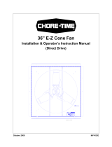
Carefully plan the installation.
Dimensions are provided for the 36" TURBO
TM
Fans with Cones (Figure 1) and
without cones (Figure 2). Be sure to allow enough space to install fans without
interfering with other fans or equipment that may be installed at a later date.
Note: See page 11 for framed opening size.
Important! Cones are wider than the actual opening cut into wall. Thus, dimension
"C" must be no less than that listed in chart below.
Planning the Installation
MV1383B 6/99
3
2
1
1
2
4
1 2
5
6
Figure 1. Planning and Layout Diagram for Cone Fans
1 2
Rough Frame
Opening
3
Minimum
4 5 6
45.38"
[115.27 cm]
43.00"
[109.22 cm]
12.00"
[30.48 cm]
47.00"
[119.38 cm]
6.85"
[17.40 cm]
52.38"
[133.05 cm]
MV1383-9B 6/99
1
1
1
2
2
2
3
4
Figure 2. Planning and Layout Diagram for Grill Fans
1 2
Rough Frame
Opening
3
Minimum
4
45.38"
[115.27 cm]
43.00"
[109.22 cm]
0"
[0.00 cm]
27"
[68.58 cm]

Installation Instructions Turbo™ Fiberglass Cone Fan and Grill Fan 36'' Belt Drive
8 MV1378B
Housing the Fan
1. Cut an opening in the wall to house the fan—the required wall opening is
provided in the chart below. See Figure 3.
2. Construct a frame in the opening of the wall for the fan using 2" x 6"
[50 x 152 mm] lumber—not supplied.
3. Insert the Fan Assembly in the wall opening and secure using the (12)
1/4 x 1-3/4 Lag Screws, Shutter Clips, and Nylon Washers provided. The
Shroud is pre-drilled (3 holes per side).The hardware must be installed as
shown in Figure 4 below. This allows for rotation of the Shutter Clips when
installing Shutter.
Installation Instructions
1
2
MV1117B-28 6/99
Figure 3. Framing Diagram
Minimum Dimension
1 2
43.00"
[109.22 cm]
43.00"
[109.22 cm]
MV1378B-3 6/99
1
2
3
Item Description Part No.
1 1/4 x 1-3/4 SS Lag Screw 40938
2 Shutter Clip 36729
3 Nylon Washer 4856
Figure 4. Fan Assembly

Turbo™ Fiberglass Cone Fan and Grill Fan 36'' Belt Drive Installing the Cone or Grill to the Fiberglass Fan
MV1378B 9
Fiberglass Cone Fan:
1. Slide the Cone onto the Shroud—the Shroud fits inside the Cone. See Figure 5.
4" slots are cut into the edge of the cone to allow expansion as the cone is slide onto
the shroud.
2. Align the holes in the Cone with the slots in the Shroud.
3. Insert the (6) Wafer Head Bolts from inside the Shroud through the Cone, place
the Nylon Washers on the Wafer Head Bolts, and thread the Nylon Nuts onto
ends of the Wafer Head Bolts.
4. Snap the Cone Grill into the slots on the outlet end of the Cone.
Installing the Cone or Grill to the Fiberglass Fan
MV1383B-40 6/99
2
3
4
6
4
5
1
Figure 5. Cone Installation
Item Description Part No.
1 Shroud 38590
2 1/4-20 Nylon Hex Nut 8916
3 Nylon Washer 4856
4 Cone 38267
5 1/4-20 x 7/8 Wafer Head Bolt 40775
6 Cone Grill 35228

Wiring Turbo™ Fiberglass Cone Fan and Grill Fan 36'' Belt Drive
10 MV1378B
Grill to Fiberglass Fan Assembly:
1. Align the holes in the Grill with the slots in the Shroud.
2. Insert the (6) Wafer Head Bolts from inside the Shroud through the Grill, place
the Nylon Washers on the Wafer Head Bolts, and thread the Nylon Nuts onto
the ends of the Wafer Head Bolts.
1. See Wiring diagram on Motor for Motor electrical connections. Follow local,
state, and national electrical codes for wiring
2. Install an electrical disconnect within reach of each Fan.
3. Route the motor cord (not supplied) toward the upper left corner of the Fan and
attach the cord to the Motor Mount using the three Cable Ties—included in the
hardware package.
Note: If an Aluminum Shutter will be installed, route the motor cord through
the Rubber Grommet—included in the hardware package see Figure 7.
Some installations may require an exit hole for the motor cord to be drilled in the side
of the Shroud. These installations must have electrical wires routed through conduit.
Note: Make sure the conduit or wires do not interfere with the Fan Blades or Shutter
operation.
MV1383B-41 6/99
3
4
6
1
5
2
5
2
1
Figure 6. Shroud Grill Installation
Item Description Part No.
1 Shroud 38590
2 Shroud Grill 37920
3 1/4-20 Nylon Hex Nut 8916
4 Nylon Washer 4856
5 Shroud Grill Mounting Loop
6 1/4-20 x 7/8 Wafer Head Bolt 40775
Wiring

Turbo™ Fiberglass Cone Fan and Grill Fan 36'' Belt Drive Shutter Installation
MV1378B 11
Plastic and Aluminum Shutters are available for the 36" Fans. Installation is
identical except where noted. See below.
1. If you have a Plastic Shutter—cut a 3/8" slot in the upper left flange of the
Shutter frame in order to route the electrical cord out the back.
2. If you have an Aluminum Shutter, route the electrical cord through the notch in
the top of the Shutter Frame. Make sure the Grommet is installed correctly in
the notch in the Shutter Frame. See Figure 7.
3. Position the Shutter, centered in the Fan Shroud, and rotate the Shutter Clips to
lock the Shutter in place. Check the Shutter for proper operation—the shutter
must be able to open and close freely without obstructions.
Note: Make sure the electrical conduit and wire does not interfere with the Fan
Blades or Shutter operation.
Shutter Installation
4
MV1384B-11 6/99
23
2
1
Figure 7. Shutter Installation
Item Description Part No.
1 Shroud 38590
2 Shutter (plastic)
Shutter (aluminum)
38027
38259
3 Grommet
(aluminum shutter only)
7256
4 Shutter Clip 36729

Maintenance Turbo™ Fiberglass Cone Fan and Grill Fan 36'' Belt Drive
12 MV1378B
Maintenance
Service and maintenance of fans should be done only by a qualified technician.
Disconnect Power prior to maintaining or cleaning the fan! The fan may start
automatically causing injury or death.
1. Grease bearings—use only high quality lithium soap base grease and clean all
dirt from Zerks before applying grease.
2. Keep the fan clean for maximum life and performance.
3. Clean Shutter, Cone and Shroud for maximum life and performance.
4. The Fiberglass Fans are shipped with the Danger Decal fastened to the Fan
Shroud. Always keep the Decal clean and readable.
Notice: If the Decals becomes damaged or unreadable, order replacement
Decals immediately.
Clean the Shroud at the approximate location where the Decal will be placed.
Peel the backing off the Decal and affix it to the Shroud.
5. Periodically check the V-Belt. If necessary, adjust the spring tension to prevent
belt from slipping.
Important! Chore-Time Equipment strongly recommends that a good alarm system
should be installed in confinement buildings to warn of power failure
and high temperature.
Chore-time Equipment also recommends that an alternate power
source be available for confinement buildings in case of power failure.
Maintenance
Motor Specifications and Part Numbers
Fan Specifications
(assembled)
Motor Specifications
Description
*Part No.
Voltage HZ Phase HP Motor
P/N
Motor
Sheave
P/N
Fan
Sheave
P/N
Fiberglass
Cone
38589-362X 208/230 60 1 .5 40158 1381 42338
38589-363X 220/240 50 1 .5 40159 8773 42338
38589-364X 208/230/460 60 3 .5 4714 1381 42338
38589-365X 220-240/380-415 50 3 .5 38566 8773 42338
Grill
38589-362X 208/230 60 1 .5 40158 1381 42338
38589-363X 220/240 50 1 .5 40159 8773 42338
38589-364X 208/230/460 60 3 .5 4714 1381 42338
38589-365X 220-240/380-415 50 3 .5 38566 8773 42338
* Replace the "X" in fan P/N with "1" for an aluminum Shutter, "2" for a plastic shutter.

Turbo™ Fiberglass Cone Fan and Grill Fan 36'' Belt Drive Fan Parts List
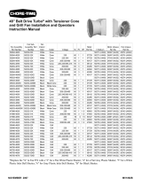
MV1378B 13
36'' Belt Drive TURBO
TM
Fan
Notice: * See page 12 for Motor and Fan Sheave Part Numbers.
Fan Parts List
MV1383-12 6/99
1
2
3
4
5
6
7
8
9
10
11
12
13
14
15
16
17
19
20
21
22
23
24
25
26
22
18
27
Item Description Part No.
1 Shutter (plastic)
Shutter (aluminum)
38027
38259
2 Cast Aluminum Fan Blade 38902
3 Fan Sheave *
4 Upper Motor Mount Support 37735
5 Shroud 37913
6 Motor varies
7 Motor Sheave *
8 Mount, Self Tension 39677
9 Spring 39684
10 Pillow Block Bearing 37912
11 Shaft 39688
12 Shroud Grill 37920
13 Outlet Cone 38267
14 Outlet Cone Grill 35228
15 Lower Motor Mount Support 37736
16 Identification Decal 2529-589
17 V-Belt 39783
18 Bushing 39681
19 Danger Decal 2527-50
20 1/4 x 1-3/4 SS Lag Screw 40938
21 Shutter Clip 36729
22 Nylon Washer 4856
23 1/4-20 x 7/8 Wafer Head Bolt 40775
24 1/4-20 Nylon Hex Nut 8916
25 36” Fan Motor Mount 39785
26 3/16 x 1 Square Key 2112-1
27 Taper Lock Hub 38909
Figure 8. Fan Parts

Plastic Shutter Turbo™ Fiberglass Cone Fan and Grill Fan 36'' Belt Drive
14 MV1378B
Plastic Shutter
3
2
3
4
1378-P4 6/99
1
MV1378B-28 6/99
Item Description Part No.
1 Shutter (plastic) 38027
2 Push Nut, 1/4" 38032
3 Shutter Rod Pivot 38702-2
4 Shutter Louver 38038-2
Figure 9. Shutter Parts

Turbo™ Fiberglass Cone Fan and Grill Fan 36'' Belt Drive Plastic Shutter
MV1378B 15
This page intentionally left blank for your notes.

Plastic Shutter Turbo™ Fiberglass Cone Fan and Grill Fan 36'' Belt Drive
16 MV1378B
Made to work.
Built to last.
Revisions to this Manual
Page No. Description of Change
6 New style of motor mount.
Contact your nearby Chore-Time distributor or representative for additional parts and information.
CTB Inc.
P.O. Box 2000 · Milford, Indiana 46542-2000 · U.S.A.
Phone (219) 658-4101 · Fax (800) 333-4191
E-Mail: [email protected] · Internet: http//www.ctbinc.com
Printed in the U.S.A.
/