68‑925‑50
Rev. B
01 13
Extron Headquarters
+800.633.9876 Inside USA/Canada Only
Extron USA ‑ West Extron USA ‑ East
+1.714.491.1500 +1.919.850.1000
+1.714.491.1517 FAX +1.919.850.1001 FAX
Extron Europe
+800.3987.6673
Inside Europe Only
+31.33.453.4040
+31.33.453.4050 FAX
Extron Asia
+800.7339.8766
Inside Asia Only
+65.6383.4400
+65.6383.4664 FAX
Extron Japan
+81.3.3511.7655
+81.3.3511.7656 FAX
Extron China
+4000.EXTRON
+4000.398766
Inside China Only
+86.21.3760.1568
+86.21.3760.1566
FAX
Extron
Middle East
+971.4.2991800
+971.4.2991880 FAX
Extron Korea
+82.2.3444.1571
+82.2.3444.1575 FAX
Extron India
1800.3070.3777
Inside India Only
+91‑80‑3055.3777
+91 80 3055 3737
FAX
© 2013 Extron Electronics All rights reserved. www.extron.com
MTP 15HD RS Series • Setup Guide
Step 6 — Power
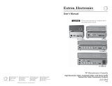
Wire the 2‑pole captive screw connectors for the included external 12 VDC power supplies (see image a
on the right). Plug them into all units.
Grounding guidelines
Extron MTP 15HD RS products can be adversely affected by electrostatic discharge (ESD) if they are
not grounded correctly.
To prevent malfunctions or product damage, an experienced installer can correctly ground an
Extron MTP 15HD RS product in either of two ways:
• Ground the power input port — Insert one end of the grounding wire to the negative or ground
pin on the power input connector (see image a on the right). Tie the other end of the wire to an
earth ground.
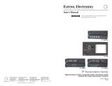
• Ground the chassis — Use a connector hex nut as shown in image b on the right. Tie the other
end of the wire to an earth ground.
If you have any questions about how to ground a product in a specic application, contact an Extron technical
support specialist.
Step 7 — Pre-Peak, Peaking, and Level
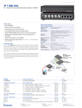
• Transmitter Pre-Peak switch — View the image and set the Pre‑Peaking switch for the best image
quality to correct for long cable runs of the entire system (including all daisy‑chained receivers).
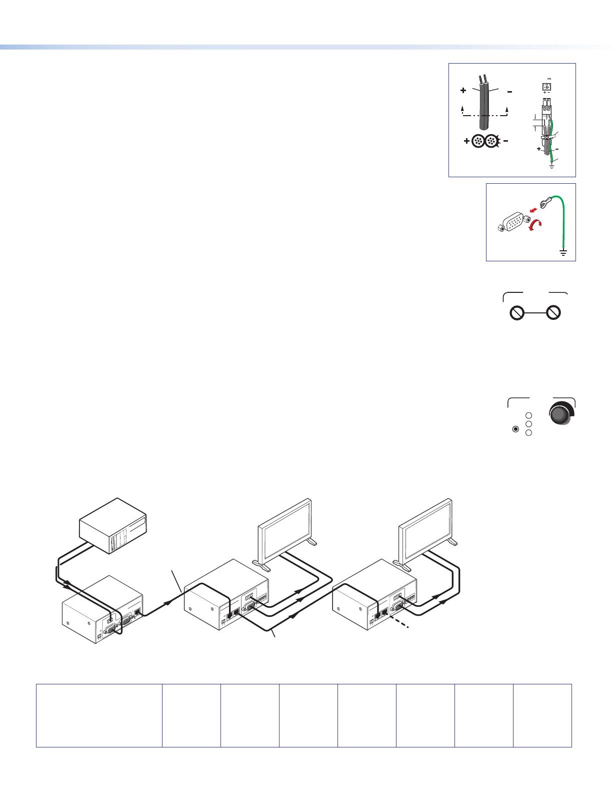
• Receiver Peaking control — View the image and adjust the Peaking control for the best image. Minimum setting
PEAKING
LEVEL
(full counterclockwise) is zero peaking.
• Receiver Level control — View the image and adjust the Level control for the best
brightness level.
Step 8 — Skew Compensation (SEQ Receivers)
Pair skew can be measured with test equipment or by viewing a crosshatch test pattern. The SEQ receivers have built‑in
skew compensation capabilities. Adjust the equalization as follows:
A. Zero the skew delay for red, green, and blue by using a small screwdriver to press and hold the Select button for
3 seconds. When the Red, Green, and Blue LEDs all go out, release the Select button.
B. Use UTP cable test equipment or examine the displayed image to determine which video signal (red, green or blue)
RED
GREEN
BLUE
SELECT
is shifted furthest to the right.
C. Select the furthest left video signal by using a small screwdriver to press and release the Select button until the LED
for the left‑shifted color (Red, Green, or Blue) lights.
D. Slowly rotate the Adjust control clockwise until the selected color is properly converged.
E. If the remaining colors are left shifted, repeat steps C and D.
INPUT
Tx
Rx
RS-232
MONITOR
POWER
12V
.5A MAX
OUTPUT
MT P T 15H D RS
PRE-PEAK
ON
OFF
RGBHV
RGBHV
RGBHV
RS-232
RS-232
RS-232
Rack Mounted
PC
DisplayDisplay
Up to Eight
Total Receivers
Extron
MTP T 15HD RS
Extron
MTP RL 15HD RS SEQ
Extron
MTP RL 15HD RS SEQ
INPUT
BUFFERED
OUTPUT
OUTPUT
POWER
12V
.5A MAX
ON
1 2 3 4 5 6
H SYNC +
V SYNC +
C SYNC
SOG
VIDEO
SPARE
1
MONO AUDIO
2
MT P R L 15H D A SE Q
INPUT
BUFFERED
OUTPUT
OUTPUT
POWER
12V
.5A MAX
MT P R L 15H D A
MT P R L 15H D A SE Q
ON
1 2 3 4 5 6
H SYNC +
V SYNC +
C SYNC
SOG
VIDEO
SPARE
1
MONO AUDIO
2
TP Cable
TP Cable
Figure 1. Example of a Typical MTP 15HD RS Application
a
Power Supply
Output Cord
SECTION A–A
Ridges
Smooth
12V
xA MAX
Tie
Wrap
Rear
Panel
Ridges
Earth
Ground
3/16"
(5 mm)
Max.
b