Page is loading ...

Form 10590149
Edition 2
September 2005
HOISTS
Series 7790-A & 7792-A
Operator’s Manual
Save These Instructions

2 Form 10590149-Edition 2
Safety Information
Operating Precautions
To aid the operator’s understanding of proper and safe use of
hoists, the publication “OVERHEAD HOISTS”,
ANSI B30.16-1981, can be purchased from:
American Standards Institute, Inc.
1430 Broadway
New York, New York 10018
• Do not use the hoist described in this manual to lift or
transport humans.
• Never try to lift a load heavier than the rated capacity of
the hoist.
• Operate hoist with caution. Operator should have a good
attitude toward safety.
• Always follow “proper operating” instructions given in this
manual.
• Allow only people who have received training in “proper
hoist operation” to operate hoists.
• Follow all operating and routine inspection procedures
prescribed in this manual.
• Operator of hoist shall operate hoist in a position that will
not be hazardous to his health.
• Do not attempt to operate hoist if it is not operating
properly.
• Before operating hoist, all routine inspection and
lubrication procedures should be completed.
Lubrication
Routine Lubrication Requirements
Lack of or an excessive amount of lubrication will affect the
performance and life of this tool Use only recommended
lubricants at below time intervals:
EVERY 8 HOURS OF TOOL OPERATION -fill lubricator
reservoir with spindle oil (29665). If an in line or air line
lubricator is not used, fill oil reservoir of built-in oiler of hoist
head.
EVERY 80 HOURS OF HOIST OPERATION - Grease fittings
in lower BLOCK HOOK ASSEMBLY and TROLLEY
WHEELS with NLGI #1 grease 33153).
EVERY 160 HOURS OF HOIST OPERATION - Fill oil
reservoir in GEAR CHAMBER with “EP” gear oil (40164).
Coat load chain of hoist with EP” gear oil (40164).
Air Supply Requirements
For maximum operating efficiency, the following air supply
specifications should be maintained to this hoist.:
• AIR PRESSURE - 90 PSIG (6 bar)
• AIR FILTRATION - 50 micron
• LUBRICATED AIR SUPPLY
• HOSE SIZE - l/2” (13 mm) I.D.
An AR0 model 128241-800 airline FILTER/REGULATOR/
LUBRICATOR (F-R-L) is recommended to maintain the
above air supply specifications.
Recommended Lubricants
After disassembly is complete all parts, except sealed or
shielded bearings, should be washed with solvent. To
relubricate parts, or for routine lubrication, use the following
recommended lubricants:
Operation
Suspending Hoist Adjusting Brake
Always select an overhead support capable of supporting
combined weight of hoist, trolley, and hoist’s load capacity.
Hook Suspended Models
• Upper hook should be firmly seated in center of hook
saddle and that safety latch is closed.
• 43059 secondary support cable is recommended.
(Dwg. )
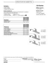
Trolley Suspended Models
• Be sure TROLLEY WHEELS are compatible with beam
being used.
• Width between outside of TROLLEY WHEELS should be
the width of beam flange + l/2”.
• If 43111 - 90’ ADAPTER is used, mount to hoist before
attempting to install trolley.
• Width is varied by using SPACERS between the hoist
body and the trolley SIDE PLATES.
• Insert an equal number of SPACERS on each inside of
the trolley SIDE PLATES until beam flange + l/2”
measurement is reached. SIDE PLATES must be
vertical.
• Insert SHAFTS (43009) through hoist, or adapter if used,
and trolley SIDE PLATES.
• Position trolley and hoist assembly on beam.
• Put an equal number of SPACERS on each end of
SHAFTS (43009) with lock washer being last.
• Tighten nuts on SHAFTS (43009). SHAFTS should
extend all the way through the NUTS.
• Move trolley over entire length of beam. If it appears the
trolley SIDE PLATES can be moved closer together and
freedom of movement will be maintained, remove an
equal number of SPACERS from inside the SIDE
PLATES and assemble these SPACERS to the outside of
the SIDE PLATES.
• Tighten NUTS to 25-30 ft. Ibs.
• Connect sufficient length of air hose to reach the
maximum travel distance of trolley.
Where Used ARO Part# Description
Air Motor 29665 1 qt. Spindle Oil
Gears and Bearings 33153 5 lb. “EP” - NLGI #l1Grease
“O” Rings & Lip Seals 36460 4 oz. Stringy Lubricant
Gearing Oil Chamber 40164 1 qt. “EP” Gear Oil
42631 CLAMP (2)
43066 RESTRAIN-
ING CABLE (5/16”
DIA. X 3½ FT. LONG
AIRCRAFT CABLE)
EQUAL NO. OF SPACERS
EQUAL NO. OF SPACERS
WIDTH OF BEAM
FLANGE PLUS 1/2”
TIGHTEN NUTS 46049
25 TO 30 FT. LBS. TORQUE
SIDE PLATES MUST
BE VERTICAL

Form 10590149-Edition 2 3
Adjusting Brake
• Properly attach rated load of hoist to load chain hook.
• Slowly raise load to 6” height above floor by slowly pulling
pull chain handle or depressing pendent control.
• Release pull chain handle or pendent control.
• If load starts to lower, tighten brake adjustment by turning
counter-clockwise until load stops lowering.
• Do not over tighten brake. If brake it too tight, the lifting
and lowering of load will be eratic, not smooth.
Setting Maximum Up and Down Speeds
• Never attempt to adjust speed regulator valves on spark
resistant hoists. They are preset by ARO.
• Attach rated load of hoist to load chain hook.
• Turn speed regulator valves clockwise until they stop.
This is lowest setting.
• Lift load by pulling pull chain or depressing pendent
control completely. As load is being lifted, turn up speed
regulator valve counter-clockwise to set the hoist at the
desired maximum “lift” speed.
• Lower load by pulling pull chain or depressing pendent
control completely. As load is lowered, turn “DN” speed
regulator valve counter-clockwise to set the hoist at the
desired maximum “lowering” speed.
• The pull chain or pendent control is used as the variable
control of lift and lowering speeds up to the maximum
speed set by the speed regulator valves.
Chain Stop
• Do not operate hoist unless chain stop is properly
attached to hoist load chain.
• Do not use chain stop to limit the distance the load is to
be lifted. The function of the chain stop is to keep the
lower hook components from striking the control arm
should an over-run condition ever occur.
Installation instructions should be completed before
attempting to operate the hoist.
Before Securing Load to Lift Chain
• Perform routine inspection and lubrication procedures.
Securing Load to Lift Chain
• DO NOT WRAP LOAD CHAIN AROUND LOAD.
Approved slings or other approved devices should be
used to provide adequate single point securing of load to
hoist load chain hook. Be sure safety latch on hook is
closed.
• Be sure load chain is not twisted or kinked.
• Hoist should be centered over the load. Always secure
load chain hook to center of load. Never lift a load from
the side or end.
• Allow only a sufficient amount of slack in load chain to
permit attaching hook to load.
Lifting and Lowering Load
1. Pull (pull chain models) or depress (pendent control
models) controls slowly to eliminate abrupt, jerky
operation.
2. Take up slack in chain slowly.
3. Speed of load lifting can be controlled by the pull chain or
pendent control. Pulling the chain further or depressing
the pendent further will result in a faster speed.
Load Chain Removal
- Drive out roll pin (106) and remove clevis from chain.
- If a chain basket is being used with hoist, remove
chain stop from end of chain.
- 2-Ton models with double reeved chain; remove
retaining ring (110) and pin (111) from anchor bracket
(112).
- Pull down on one end of control arm (68) to release
brake and pull chain from housing.
Load Chain Installation
-
A new chain should never be used on a worn
pocketwheel. Replace chain and pocketwheel as a pair.
- Place hoist in vise and clamp on upper hook mount.
- Remove housing cap (95), brake spring (94) and brake
shoes (92).
- Turn brake wheel (93) by hand to rotate pocketwheel
while carefully feeding chain thru chain guide and
around pocketwheel (64).
- Pull sufficient chain thru housing to allow end link to be
attached to anchor lug on housing.
CAUTION
Chain must be positioned around pocketwheel so weld
on the standing links face outward from pocketwheel -
see illustration.
- End link of chain must also be positioned properly to
permit attaching to anchor lug on housing without
twisting of chain.
WARNING
Do not attempt to feed chain over pocketwheel by air
power as chain will be pulled thru housing at a very fast
rate.
- Attach other end of chain to lower hook (or anchor
bracket on 2-Ton models).
REGULATOR
VALVE S
UP
UP
DN
DN
POCKET WHEEL
CHAIN GUIDE
CHAIN WELD

4 Form 10590149-Edition 2
Routine Inspection
The type of application for a hoist varies so greatly it is
impractical to recommend an exact time-table for inspection
of the hoist. Where hoist is subjected to continuous operation
with capacity loads, it is recommended the unit be inspected
twice a week. If the application is less demanding, the unit
should be inspected twice a month. In general, the frequency
of inspection should be determined by the severity of the
application. The user of a hoist should be guided by any
existing federal, state or local regulations governing the use,
testing or inspection of the hoist.
If any damage or malfunction is evident do not operate hoist
until all repairs have been made and hoist tested for proper
operation.
The following points and areas are recommended for
inspection:
Load Chain and Anchor Points
• Visually check for nicked, gouged, twisted, bent,
corroded, rusted, worn or broken links. Check ends of
chain where chain is anchored to hoist frame and where
chain is fastened to lower hook. Check anchors and pins
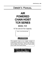
• Check chain elongation with a vernier caliper as shown.
IF VISUAL CHECK REVEALS NO DEFECTS,
PROCEED AS FOLLOWS:
LAY USED CHAIN ON FLAT SURFACE AND MEASURE
BETWEEN FIVE (5) LINKS AS SHOWN.
MEASUREMENT SHOULD BE TAKEN ON PORTION
OF CHAIN WHICH HAS MOST PASSED OVER THE
POCKET WHEEL.
IF MEASUREMENT TAKEN IS (SEE TABLE) INCHES
OR MORE, CHAIN SHOULD BE REPLACED.
IT IS NOT INFERRED that a chain is safe prior to the
occurence of elongation of the chain. It is inferred ONLY, that
when said elongation is evident, the chain must be replaced.
Other factors, such as those mentioned as a visual check,
may render chain unsafe long before replacement due to
elongation is necessary. NOTE: New chain should never be
used on a worn pocketwheel, replace chain and pocketwheel
as a pair. Chain should also be replaced when replacing
brake shoes.
Hooks and Suspension
• Check upper and lower hooks and related parts for bent,
worn, cracked, broken or otherwise damaged parts.
• On trolley suspended models, check conditions of trolley
parts, trolley adapter and related parts.
• Check for loose bolts, nuts, or rivets.
Brake
1. Check brake operation - see Adjusting Brake, page 2.
2. Check brake linings and components. NOTE: When
replacement of brake shoes is indicated, they must be
replaced as a pair. Also replace chain at this time.
Gears, Bearings and Pocketwheel
• Check teeth on gears and motor shaft pinion.
• Check pockets of pocketwheel.
• Check bearings for noisy operation indicating wear.
Throttle Valve Head and Gears
• Check valve body, valves, and “O” rings on valves.
• Check gear teeth and bearings.
Air Motor
• Check end faces of rotor for roughness and blade slots
for wear or burrs. A new blade should slide in and out of
slots without binding.
• Check blades for wear, warpage or other damage.
• Check cylinder bore diameter for rough circular grooves
from scoring. A badly scored cylinder cannot be restored
by honing since it will only enlarge bore diameter,
widening seal point between rotor and cylinder, hindering
free exhaust of air and result in loss of speed and power.
• Check end plates for wear or scoring. Check bearings.
• Follow all operating and routine inspection procedures
prescribed in this manual.
• Disconnect air supply from hoist before performing
maintenance or service procedures.
• Never apply excessive pressure by a holding device
which may cause distortion of a port.
• Apply pressure evenly to parts which have a press fit.
• Apply even pressure to the bearing race that will be press
fitted to the mating part.
• Use correct tools and fixtures when servicing this tool.
• Don’t damage “O” rings when servicing tool.
• Use only genuine ARO replacement parts for this tool.
When ordering specify part number, description, tool
model number and serial number.
IDENTIFICATIONS
MARKINGS
NEW CHAIN
MEASUREMENT
REPLACE CHAIN
4.291 4.366
4.340 4.415
5/16
VERNIER CALIPER
NEW CHAIN
.8583 PITCH
DETERMINE TYPE OF IDENTIFICATION MARKINGS EMBOSED ON LOAD CHAIN
AND FIND DIMENSIONS IN TABLE
or
ARO
OC
R
CORRECT
HOOK OPENING
1-1/4" ON 1-TON UPPER & LOWER HOOKS
1-3/8" ON 2-TON UPPER & LOWER HOOKS

Form 10590149-Edition 2 5
Maintenance
Dissassembly
Head Disassembly
To remove head section from housing without disassembling
head components, remove head with control rod (59)
attached to gear (25). To accomplish this -
- Remove two screws (96) and housing cap (95).
- Drive out roll pin (61) and remove brake block (60).
- Drive out roll pin (69) from control arm (68).
- Remove six screws (22) and washers (23).
- Remove head section and control rod from housing as
one unit.
To disassemble head components without removing head
section from hoist:
- Remove two screws (96) and housing cap (95).
- Drive out roll pin (69) from control arm (68).
- Drive out roll pin (26) from gear (25) and drive control
rod (59) back thru gear (25) and remove gear.
- Remove adapters (19), valves (17) and (29) and valve
body (15).
- Remove set screws (24) and regulator valves (28).
CAUTION
do not attempt to adjust or remove regulator valves (28)
from spark-resistant hoist models - these valves are
pre-set at fatctory.
- Remove adapter (1) and screen (2).
- Remove retaining ring (4), swivel (3), swivel body (6)
and screen (8).
- Remove two screws (9), washers (10), exhaust
deflector (11), screen (12) and muffler filler (13).
NOTE: When reassembling head to housing a new Gasket
(31) must be installed. Tighten Screws (22) to approximately
60 in-lbs. torque. When tightening these screws it is
recommended that an air line be attached to the air inlet and
the hoist operated to insure that no binding of the motor
occurs. Tighten screws alternately and gradually until desired
torque is reached without binding of motor. Lubricate all
O-Rings with O-Ring lube (36460) before assembling. Insure
O-Ring (32) is properly positioned in head.
- Assemble valve body (15) into head - see “Timing of
Head”, this page.
- Assemble o-rings (27) to regulator valves (28).
- Assemble regulator valves (28) to head and secure
with set screws (24). NOTE: groove in regulator valve
must be aligned to accept set screw. See setting hoist
speed, page 2.
- Assemble muffler filler (13), screen (12) and exhaust
deflector (11) to head and secure with washers (10)
and screws (9).
- Clean and assemble screen (8) to head.
- Assemble o-rings (5) and (7) to swivel body (6) and
assemble body to head.
- Assemble swivel (3) to swivel body and secure with
retaining ring (4).
- Clean and assemble screen (2) and inlet adapter (1) to
swivel.
- Fill oil reservoir in head with spindle oil 29665.
Pendent Control Disassembly
- Remove pendent hoses from fittings (156) and (165).
- Remove adapter (166) from head releasing strain
cable.
- Remove screws (168), springs (170) and valves (171).
Pendent Control Assembly
- Lubricate o-rings (172) and assemble to valves (171).
- Assemble valves (171) and springs (170) to handle.
- Lubricate o-rings (169) and assemble to screws (168).
- Assemble screws (168) to handle securing valve
components.
Pendent Cylinder Disassembly
- Unthread cylinder (157) from adapter (163).
Pendent Cylinder Assembly
- Assemble piston rod (160) to piston (159).
- Lubricate and assemble o-ring (158) to piston (159).
- Lubricate and assemble o-rings (162) and (164) to
adapter (163).
Motor Disassembly
- Remove head section - see “Head Disassembly”.
- Remove motor from housing.
- Remove retaining ring (36); motor assembly will come
apart,
Motor Assembly
- Lubricate bearings (37) with NLGI #1 “EP” grease
(33153) and assemble bearings to end plate (38) and
(43) - shielded side of bearing facing out.
- Assemble end plate (43) to spindle (45) and slide up to
shoulder of spindle.
- Assemble key (44) to key slot in spindle (45).
- Assemble rotor (41) over spindle aligning key way and
key (44).
- Assemble cylinder (39) over rotor (41) and insert
blades (42) into blade slots of rotor - straight side of
blade out.
- Assemble end plate (38) to spindle and align hole in
end plate with roll pin (40).
- Secure assembled parts to spindle with retaining ring
(36).
UP DN
ENDS OF VALVE BODY FLUSH WITH BUSHING
IDENTIFICATION MARK "x" ON END OF VALVE BODY
TIMING GROOVES
ON VALVE BODY
UP DN
GEAR [25]
UP DN
STEP 1 :- POSITION HOIST SO YOU ARE FACING END WITH AIR INLET, WITH VALVE
PARTS AND GEAR [25] REMOVED, PLACE VALVE BODY IN VALVE OPENING. INSERT
FINGER IN EACH END OF VALVE OPENING AND ALIGN END OF VALVE BODY WITH ENDS
OF BUSHING.
NOTE: VALVE BODY MUST BE INSTALLED WITH IDENTIFICATION MARK AS SHOWN.
STEP 2 :- WITH BRAKE RELEASE BLOCK ASSEMBLED TO CONTROL ROD, INSERT ROD
THROUGH BRAKE END OF HOUSING, THROUGH CONTROL ARM [68] AND ON THROUGH
HOUSING STOPPING BEFORE ROD PROTRUDES FROM HEAD.
A
SSEMBLE GEAR [25] TO HEAD ALIGNING CENTER TOOTH OF GEAR BETWEEN TWO
GROOVE MARKINGS ON THE VALVE BODY AS SHOWN.
A
SSEMBLE CONTROL ROD THROUGH GEAR AND SECURE WITH ROLL PIN [26]. SECURE
CONTROL ARM TO ROD WITH ROLL PIN [69].
STEP 3 :- ASSEMBLE O-RINGS [16] TO VALVES [17] AND [19] AND ASSEMBLE VALVES
INTO HEAD AS SHOWN. ASSEMBLE O-RINGS [18] TO ADAPTERS [29] AND O-RINGS
[20] TO VALVE CAPS [21] AND ASSEMBLE TO HEAD.

6 Form 10590149-Edition 2
- Assemble motor to housing.
- Lubricate and assemble o-rings (35) into counterbore
of end plate (38).
- Assemble new gasket (31) and head to housing.
Brake and Gearing Disassembly
- Remove two screws (96) and housing cap (95).
- Carefully slide brake spring (94) part way off brake
shoes (92) and using brake spring spreader (33541),
remove brake spring (94).
CAUTION
remove brake spring (94) with due regard for safety as
spring is assembled with considerable tension.
- Remove brake shoes (92) and steel balls (91).
- Align hole in brake wheel (93) with hole in end plate
(89) and insert a punch or pin thru holes to secure
brake wheel.
- Remove cotter pin (74), nut (99) and washer (100).
- Remove brake wheel (93).
- Remove roll pin (61) and brake block (60).
- Remove four screws (103) and washers (104).
- Place blade type screwdrivers, or similar tool, at
opposite sides behind edge of end plate (89) and pry
out on end plate to remove from housing.
- Remove gearing assembly.
- Remove retaining rings (70) and (82).
- Push on threaded end of shaft (72) and remove out
opposite end of gear carrier (75).
- Remove bearing (80), spacer (79) and shafts (78),
releasing gears (77) and bearing races (76).
- Remove retaining ring (83) and bearing (81).
- Remove four shoulder screws (101) and washers
(102) and fixed ring gear (84).
- Remove seal (88) for replacement only.
Assembly
Brake and Gearing Assembly
- Lubricate and assemble six o-rings (86) into
counterbores of fixed ring gear (84).
- Assemble seal (88) to end plate (89) - lip of seal facing
out.
- Assemble wave washer (87) and end plate (89) to
fixed ring gear (84) and secure with four washers (102)
and shoulder screws (101),
- Assemble gears (77), bearing races (76) and shafts
(78) to gear carrier (75).
- Assemble spacer (79) to gear carrier aligning spacer
with notched ends of shafts (78).
- Lubricate bearings (73) and (80) with NLGI #1 “EP”
grease (33153) and assemble to gear carrier (75).
- Lubricate bearing (71) with NLGI #1 “EP” grease
(33153) and assemble to shaft (72).
- Assemble shaft (72) to gear carrier (75) and secure
with retaining ring (70).
IMPORTANT: punch marks on gears (77) indicating
aligned teeth must be held in alignment with punch
marks on gear carrier (75) when shaft (72) to assembled
to gear carrier.
- Lubricate bearing (81) with NLGI #1 “EP” grease
(33153) and assemble to shaft (72).
- Assemble retaining ring (82) and (83) to shaft (72).
- Assuming o-ring (53) and ring gear (55) are
assembled to housing (see housing assembly);
assemble gearing into ring gear (55).
- Lubricate and assemble o-ring (54) over fixed ring
gear (84) and slide up to end plate.
- Assemble fixed ring gear and end plate to gearing and
housing. Use reasonable caution so as not to damage
seal (88) in end plate.
- Secure end plate and components to housing with
washers (104) and screws (103).
- Assemble brake wheel (93) to shaft (72) and secure
with washer (100), nut (99) and cotter pin (74).
- Assemble control rod (59) thru housing, hangers (62)
and control arm (68).
- Secure control arm (68) to rod with roll pin (69).
- Assemble brake block (60) and roll pin (61) to control
arm (59).
- Assemble screw (90), balls (91), brake shoes (92) and
brake spring (94).
- Assemble housing cap (95) and secure with two
screws (96). See brake adjustment, page 2.
- Fill gearing oil chamber with 6 to 7 ounces (to lower
plug hole level) “EP” gear oil (40164).
Housing Disassembly
- Remove head, motor and gearing sections.
- Remove screws (67), washers (66) and plate (65).
- Place brass or wood block in pocketwheel cavity to
prevent shaft (50) from turning.
- Remove nut (58), washer (57), o-ring (56) and ring
gear (55).
- Remove retaining ring (46) from “motor end” of
housing.
- Remove shaft (50) with bearing (47).
- Remove pocketwheel (64) and chain guide (63).
- Remove seal (52) for replacement only.
Housing Assembly
- Assemble bearing (47) and retaining ring (46) to “brake
end” of housing.
- Assemble chain guide (63) and pocketwheel (64) to
housing.
NOTE: part number stamped on face of pocketwheel
must face “motor end” of housing.
- Assemble retaining ring (48) and bearing (47) to shaft
(50).
- Insert shaft (50) into housing and thru pocketwheel
(64) and bearing (47).
- Assemble retaining ring (46) to housing.
- Assemble plate (65), washers (66) and screws (67) to
housing.
- Assemble new seal (52) into housing with lip of seal
facing out.
- Lubricate and assemble o-ring (53) into groove in
housing.
- Assemble ring gear (55), o-ring (56), washer (57) and
nut (58).
- Assemble motor, gearing and head sections to hoist.
PUNCH MARKS ON GEARS AND PUNCH MARK
ON CARRIER MUST BE IN ALIGNMENT

Form 10590149-Edition 2 7
Upper Hook Disassembly
- Remove nuts (153), washers (152) and bracket (150).
- Drive out roll pin (147) - One-Ton Models. Roll pins
(155) and (154) - Two-Ton Models.
- Remove collar (143) and balls (144) - One-Ton
Models. Collar (116), thrust bearing (120) and bearing
races (119) - Two-Ton Models.
Upper Hook Assembly
Position hook on bracket (150).
Apply a liberal amount of grease to groove of collar (143) and
assemble eleven balls (144) to collar.
Slide collar and balls over shank of hook and secure with roll
pin (147) - One-Ton Models.
Apply a liberal amount of grease to thrust bearing (120) and
assemble thrust races (119) and bearing (120) to shank of
hook. Secure with roll pins (154) and (155) - Two-Ton
Models.
Assemble bracket (150), shafts (151), washers (152) and
nuts (153).
CAUTION
Do not over-tighten nuts (153); tighten 25 to 30 ft. Ibs.
torque.
Lower Hook Disassembly
1-Ton Models
- Remove snap ring (139).
- Slide snap ring (139) and sleeve (140) up on chain and
remove pin (146).
- Separate connector (142) from bucket (145) and
remove pin (141).
- Drive out roll pin (147) and remove hook from bucket
(145).
2-Ton Models
- Remove bolts (134), washers (133) and shrouds (130).
- Remove bolts (124), (129), washers (125), and
spacers (126).
- Remove shaft (128), spacers (127) and sheave (114).
- Drive out roll pins (118) and (117).
- Remove collar (116), thrust bearing (120), bearing
races (119) and hook (123).
Lower Hook Assembly
1-Ton Models
- Slide snap ring (139) and sleeve (140) on end of load
chain.
- Position end of load chain in connector (142) and
secure with pin (141).
- Assemble hook (149) to bucket (145).
- Apply a liberal amount of grease to groove of collar
(143) and assemble eleven balls (144) to collar.
- Assemble collar (143) over shank of hook and secure
with roll pin (147).
- Assemble bucket (145) to connector (142) and secure
with pin (146).
- Slide sleeve (140) over bucket (145) and secure with
snap ring (139).
2-Ton Models
- Assemble hook (123) to yoke (121).
- Apply a liberal amount of grease to thrust bearing
(120) and assemble bearing races (119) and thrust
bearing to collar (116).
- Assemble collar (116) over shank of hook and secure
with roll pins (117) and (118).
- Lubricate roller bearing of sheave (114) and assemble
bearing race (115) to sheave.
- Assemble spacers (127), sheave (114) and shaft (128)
to yoke (121).
- Assemble washers (125) and spacers (126) to bolts
(124) and (129) and secure bolts to shaft (128).
- Feed load chain around sheave - with weld of standing
links facing out from sheave and attach end of chain to
anchor bracket (112) with pin (111) and retaining rings
(110).
- Position shrouds (130) on lower hook assembly and
secure with washers (133) and bolts (134).

8 Form 10590149-Edition 2
CAUTION: TIGHTEN NUTS 25 TO 30 FT.
LBS. TORQUE ONLY.
96
95
94
92 92
91
91
88 85
191
190
189
187
186
188
187
186
187
188
186
187
187
189
190
191
189
193
191
189193192
189
193
84
81
80
78
76
77
76
74
73
70
58
57
56
55
46
47
54
53 52
59
60
61
7172
75
76
77
76
78
79
82
83
85
86
87
89
104
103
101
106
105
108
109
110
112
107
108
111
110
113
115
114
116
125
127
120
117
118
119
127
125
130
133
134
139
137
138
107
105
106
136
137
142
143
145
147
148
140
141
144
146
149
129
126
128
135
124
126
121
122
123
130
102
100
99
98
97
90
93
*
*
*
+
++
*
*
*
*
*
*
X
Y
*
*
*
*
*
*
*
*
*
*
*

Form 10590149-Edition 2 9
62
156
180
157 158 159 160 161 162 163 164
165
166
167
174
175
176
177
178
179
173172170168
169 171
181
182
183 184
185
152
( 2-TON MODELS) 123
( 1-TON MODELS) 149
122 ( 2-TON MODELS)
148 ( 1-TON MODELS)
150
153
144
143
119
116
120
151 152
153
154
155
147
CAUTION : TIGHTEN NUTS 25 TO 30 FT.
LBS. TORQUE ONLY.
++ ASSEMBLE WITH SPLIT SIDE ONE UP AND ONE DOWN.
+ ASSEMBLE WITH SPLIT SIDE ONE UP OR DOWN.
++
+
++
*
*
(1-TON MODELS)
(2-TON MODELS)
DOWN UP
68
69
63
64
65
66
67
X
X
X
X
X
PART NUMBER
THIS SIDE.
*
*
*
*
*
*
*
*
*
ITEMS INCLUDED IN SERVICE KIT PART NUMBER 41619-1.
ITEMS INCLUDED IN SERVICE KIT PART NUMBER 41759.
ITEMS INCLUDED IN 43004 SHAFT ASSEMBLY
*
DO NOT ATTEMPT TO ADJUST OR REMOVE THESE VALVES ON
SPARK RESISTANT MODELS.
50 49 44 37 41
39
38
37
36
34
33
31 32
30
33
34
12
11
9
432
1
5
6
7
8
15 16 17 18 19 20
21
22
23
25
24
26
28
241629182021
3540424345464748
51
19
27
10
13
14
*
*
*
*
*
*
*
*
*
UP
DN
x
X
Y
*
*
**
*
*

10 Form 10590149-Edition 2
Parts List
Sl. no. Description Part no. Sl. no. Description Part no.
Head Assembly (standard models) includes
items 1 thru 21, 24 thru 30, 33 and 34 with
adapter (46211) 46126-2
MOTOR ASSEMBLY (includes items 36
thru 45) 42977
* 36 Retaining Ring Y145-22
Head Assembly (spark-resistant models)
(includes items 1 thru 19, 24 thru 30, 33, 34
and 59 with adapter 46212) 46126-3
* 37 Bearing (2 req'd) 42086
38 End Plate 43076
39 Cylinder (includes item 40) 43130
1 Adapter 40 Roll Pin Y178-73
for standard models 46211 41 Rotor 43068
for spark-resistant models 46212 * 42 Blade (8 req'd) 43067
2 Screen 31648 43 End Plate 42958
3 Swivel 46839 * 44 Key 30934
SWIVEL KIT (includes items 1 thru 3) 45 Spindle 42959
for standrad models (includes adapter 46211) 46840 *46 Retaining Ring (2 req'd) Y147-200
for spark-resistant models (includes adapter
46212) 46841
*47 Bearing (2 req'd) 92962-ARO
* 48 Retaining Ring Y145-25
4 Retaining Ring Y145-28 * 49 Seal 42149
* 5 "O" Ring (2 req'd) Y325-115 50 Shaft 42960
6 Swivel Body 33314 SHAFT ASSEMBLY (includes items 49
and 50) 43004
* 7 "O" Ring Y325-17
* 8 Screen 46072 Capacity Label (not shown)
9 Cap Screw (2 req'd) Y154-53 1000 kg (2200 lb.) 46067-3
10 Washer (2 req'd) Y14-10 2400 lb. 44198-7
11 Exhaust Deflector 42954 2000 kg (4400 lb) 46067-4
12 Screen 42957 1500 lb. 44198-9
* 13 Muffler Filler 42956 3000 lb. 44198-10
14 Head (includes roller bearing 33239 and
three pipe plugs Y227-3, not shown) 46125
51 Housing (includes item 52, pipe plug
Y227-2-L, set screw Y29-44 and
warning label 43640, not shown) 42996
15 Valve Body 43079
* 16 "O" Ring (2 req'd) 04614574 Nameplate (not shown) 41596
17 Lift Valve 43080 Drive Screw (4 req'd) (not shown) Y60-44
* 18 "O" Ring (2 req'd) Y325-25 *52 Seal 42967
19 Adapter (2 req'd) 40017 * 53 "O" Ring Y325-46
* 20 "O" Ring (2 req'd) (not required with pendent
control models) Y325-116
* 54 "O" Ring Y325-155
55 Ring Gear 42963
21 Valve Cap (2 req'd) (not required with
pendent control models) 34026
* 56 "O" Ring Y325-211
* 57 Washer Y117-875
22 Cap Screw (6 req'd) Y154-54 58 Nut 42964
23 Washer (6 req'd) Y14-10 59 Control Rod 46121
24 Set Screw (2 req'd) 60 Brake Block 34029
for standard models 41598 61 Roll Pin Y178-60
for spark-resistant models 41627-1 62 Hanger (2 req'd) 43033
25 Gear 34022 63 Chain Guide 42989
* 26 Roll Pin Y178-56 64 Pocket Wheel 42961-ARO
27 "O" Ring (2 req'd) Y325-111 65 Plate 42990
28 Valve (2 req'd) 43107 * 66 Washer (6 req'd) Y117-10
29 Descent Valve 43081 *67 Cap Screw (6 req'd) Y154-52
30 Oilite Casting 33190 68 Control Arm 43133
* 31 Gasket 43008 69 Roll Pin Y178-55
* 32 "O" Ring Y325-9 70 Retaining Ring 42975
33 Washer (2 req'd) 31389 71 Bearing 41864
34 Oil Screw (2 req'd) 30747 72 Shaft 43072-1
* 35 "O" Ring (2 req'd) Y325-12 73 Bearing 40048

Form 10590149-Edition 2 11
Parts List
Sl. no. Description Part no. Sl. no. Description Part no.
* 74 Cotter Pin Y15-32 115 Bearing Race 43041
75 Carrier 42965 116 Collar 43032
76 Bearing Race (4 req'd) 42364 117 Roll Pin Y178-128
77 Gear (2 req'd) 42971 118 Roll Pin Y178-117
78 Shaft (2 req'd) 42973 119 Bearing Race (2 req'd) 37391
79 Spacer 42974 120 Thrust Bearing 37392
* 80 Bearing 42968 121 Yoke 43037
* 81 Bearing Y65-12 * 122 Safety Latch (includes bolt, nut and spring) 420230
* 82 Retaining Ring Y147-112 123 Hook
* 83 Retaining Ring Y145-18 Steel Hook for standard 2 ton models
(includes item 122)
43031
Gearing Assembly (includes items 70 thru
73 and 75 thru 83) 42976
Bronze Hook for 2400 and 3000 lb spark-
resistant models (includes item 122) 43083
84 Fixed Ring Gear 42966
85 Roll Pin (2 req'd) Y178-101 YOKE AND HOOK ASSEMBLY with steel
hook, for standard 2 ton models (includes
items 114 thru123)
43047
86 "O" Ring (6 req'd) Y325-10
87 Wave Washer 40041
* 88 Seal 04565511 YOKE AND HOOK ASSEMBLY with
bronze hook, for 2400 and 3000 lb spark-
resistant models (includes items 114 thru
123) 43099
89 End Plate (Includes item 88, bracket
42980-1 and roll pin Y178-44, not shown)
43118
END PLATE and RING GEAR
ASSEMBLY (includes items 84 thru 89,
101 and 102
43003
LOWER BLOCK ASSEMBLY for standard
2 ton models (includes items 114 thru 129
with steel hook)
43048
90 Screw 37701
91 Ball (2 req'd) Y16-10 LOWER BLOCK ASSEMBLY for spark-
resistant models (includes items 114 thru
129 with bronze hook) 43101
* 92 Brake Shoe (2 req'd) 42994
93 Brake Wheel 43071-1
*94 Brake Spring 42982 124 Bolt Y5-85-C
95 Housing Cap 42979 125 Washer (2 req'd) Y14-816
96 Cap Screw (2 req'd) Y154-54 126 Spacer (2 req'd) 43039
97 Drive Screw (4 req'd) Y60-43 127 Spacer (2 req'd) 43042
98 Capacity Plate 128 Shaft 43038
1500 lb. 45278 129 Bolt (includes grease fitting 35323) 40072
1 ton 41589 130 Shroud (2 req'd)
2400 lb. 43116 for standard 2 ton models 43043
3000 lb. 43050 for 2400 lb models (includes capacity plate
43123 and four drive screws Y60-30, not
shown)
43121
2 ton
* 99 Nut Y12-106-C for 3000 lb models (includes capacity plate
45281 and four drive screws Y60-30, not
shown) 45282
* 100 Washer Y117-616
101 Shoulder Screw (4 req'd) 42993
102 Washer (4 req'd) Y1-416-C 133 Washer (3 req'd) Y14-416
103 Cap Screw (4 req'd) Y99-41 134 Cap Screw (3 req'd) Y99-49
104 Washer (4 req'd) 30997 135 Nut (3 req'd) Y242-12-B
105 Clevis 34987 136 Cap Screw Y99-44
106 Roll Pin Y178-104 137 Chain Stop (2 req'd) 43127
107 Link Chain 138 Nut Y107-4-Z
for 1 ton, standard models, 10 ft (3 m) lift 42988-11 Chain Stop Assembly (includes items 136
thru 138) 43128
for 2400 and 3000 lb, spark-resistant
models, 10 ft (3 m) lift 43095-22 139 Snap Ring 42999
108 Retaining Ring (2 req'd) Y145-8 140 Sleeve 42998
109 Anchor Pin 43020 141 Pin 43702-1
* 110 Retaining Ring (2 req'd) Y145-2 142 Connector 43028
111 Pin 42970 143 Collar 34321
112 Anchor Bracket 43034 * 144 Ball (11 req'd) Y16-10
113 Chain Stop 43051-1 145 Bucket 43019
114 Sheave and Bearing 43046 146 Pin 43702-2

12 Form 10590149-Edition 2
Parts List
Sl. no. Description Part no. Sl. no. Description Part no.
147 Roll Pin Y178-122 173 Screw (4 req'd) Y61-85-C
* 148 Safety Latch (includes bolt, nut and spring) 35023 174 Connector (3 req'd) Y54-2
149 Hook 175 Handle 43122
Steel Hook for standard 1 ton models 34337 176 Roll Pin (2 req’d) y178-58
Bronze Hook for 1500 lb spark-resistant
models 34651
177 Lever (up) 45616-2
178 Lever (down) 45616-1
LOWER HOOK ASSEMFLY for 1 ton
models (includes items 143 thru 145 and
147 thru 149 with steel hook)
43000
179 Guard Assembly (includes warning plate
44197 and four rivets 45119)
44312
LOWER HOOK ASSEMBLY for 1500 lb
spark-resistant models (includes items 143
thru 145 and 147 thru 149 with bronze hook 43110
HANDLE ASSEMBLY (includes items
168 thru 179)
43102
PENDENT CONTROL ASSEMBLY
(includes items 156 thru 179) 43106-6
UPPER HOOK ASSEMBLY for standard 1
ton models (includes items 143, 144 and
147 thru 150 with steel hook 43002
180 "S" Hook (2 req'd) 37659
181 Handle (2 req'd) 33268
182 Control Handle (includes item 185) 44806
UPPER HOOK ASSEMBLY for 1500 lb
spark-resistant models (includes items 143,
144 and 147 thru 150 with bronze hook 43097
183 Sash Chain (2 req'd) 37657-5
184 Anchor (2 req'd) 37723
185 Warning Label 44596
UPPER HOOK ASSEMBLY for standard 2
ton models (includes items 116, 119, 120,
122, 123, 150, 154 and 155 with steel hook) 43049
PULL CHAIN CONTROL ASSEMBLY
(includes items 180 thru 185)
40004-5
186 Trolley Wheel (4 req'd)
UPPER HOOK ASSEMBLY for 2400 and
3000 lb spark-resistant models (includes
items 116, 119, 120, 122, 123, 150, 154 and
155 with bronze hook)
43096 for "I" Bean mounting
for standard 1 ton models 41015
for spark-resistant 1 ton models 41015-1
150 Bracket for standard 2 ton models 40149
for 1 ton and 1500 lb models 42997 for spark-reistant 2 ton models 40149-1
for 2 ton, 2400 and 3000 lb models 43030 for "H" Beam mounting (flat tread wheel)
151 Mounting Rod (2 req'd) 43001 for standard 1 ton models 45376
152 Washer (4 req'd) 46049 for standard 2 ton models 45377
153 Nut (4 req'd) 46049 187 Spacer (8 req'd)
154 Roll Pin Y178-128 for 1 ton models 41022
155 Roll Pin Y178-117 for 2 ton modeles Y13-12-C
CYLINDER ASEMBLY (2 req'd) (includes
items 156 thru 164)
43017 188 Side Plate (2 req'd) 43052
189 Lock Washer (8 req'd) Y14-750
156 Elbow Y54-23 190 Nut (4 req'd) Y12-12
157 Cylinder 41064-1 191 Nut (4 req'd) 46049
158 "O" Ring Y325-222 192 Shaft (2 req'd) 43009
159 Piston 41066 193 Washer (84 req'd) 43014
160 Piston Rod 42955 194 Nameplate (not shown) 44081-1
161 Spring 33981 195 Skid Bracket (4 req'd) (not shown) 44618-1
162 "O" Ring Y325-13 196 Rivet (8 req'd) Y193-33
163 Adapter 41067 TROLLEY ASSEMBLY
164 "O" Ring Y325-116 for spark-resistant models (includes
items 186 thru 196)
165 Elbow Y54-23
166 Adapter (2 req'd) 33989 for 1 ton models 7763-BC
167 Hose Assembly (includes hoses and strain
cable) 43103-6
for 2 ton models 7764-BC
for standard models (includes items 186
thru 194)
168 Screw (2 req'd) 37511
169 "O" Ring (2 req'd) Y325-111 for 1 ton models ("I" Beam)
170 Spring (2 req'd) 32858 for 1 ton models ("H" Beam) 7795-FT
171 Valve (2 req'd) 34757 for 2 ton models ("I" Beam) 7796
172 "O" Ring (2 req'd) Y325-6 for 2 ton models ("H" Beam) 7796-FT
* SERVICE KIT: includes items marked * 41619-1
SERVICE KIT: includes items marked 41759

Form 10590149-Edition 2 13
Model Identification
Spark Resistant Models
* FOR TROLLEY MOUNTING - TROLLEY MUST BE ORDERED SEPARATELY
** STAINLESS STEEL LINK CHAIN AND BRONZE HOOKS.
Model No. Upper Mounting Type Control Type Load Chain Lbs. (Kg.) Capacity
7790-A9 Hook Ass’y 43002 Pull Chain Link
2,200
(1000 Kg)
7790-A11 None * Pull Chain Link
7790-A13 Hook Ass’y 43002 Pendent Link
7790-A15 None * Pendent Link
7792-A9 Hook Ass’y 43049 Pull Chain Link
4,400
(2,000 Kg)
7792-A11 None * Pull Chain Link
7792-A13 Hook Ass’y 43049 Pendent Link
7792-A15 None * Pendent Link
Model No. Upper Mounting Type Control Type Load Chain Lbs. (Kg.) Capacity
7790-A21 Hook Ass’y 43097 Pull Chain Link **
1,500
(680 Kg)
7790-A22 None* Pull Chain Link **
7792-A21 Hook Ass’y 43096 Pull Chain Link **
2,400
(1,089 Kg)
7792-A22 None* Pull Chain Link **
7792-A23 Hook Ass’y 43096 Pull Chain Link **
3,000
(1,361 Kg)
7792-A24 None* Pull Chain Link **

14 Form 10590149-Edition 2
Notes

Form 10590149-Edition 2 15
Notes

www.irtools.com
© 2005 Ingersoll-Rand Company
/