Page is loading ...

1
RFA
PACKAGED AIR CONDITIONERS AND HEAT PUMPS
ROOF TOP
FOR OUTDOOR INSTALLATION
INSTALLATION AND OPERATION MANUAL
R
E
F
R
I
G
E
R
A
N
T
G
A
S
E
C
O
-
F
R
I
E
N
D
L
Y
i migliori gradi centigradi

2
The manufacturer declines all the responsabilities regarding inaccuracies contained in this manual, if due to printing or typing mistakes.
The manufacturer reserves the right to apply changes and improvements to the products at any time and without notice.
Dear Customer,
thank you for having purchased a FERROLI product. It is the result of many years of experiences and of particular research stu-
dies and has been made with top quality materials and advanced technologies. The CE mark guarantees that the products satisfy
all the applicable European Directives.
The qualitative level is kept under constant control and FERROLI products therefore offer Safety, Quality and Reliability.
Due to the continuos improvements in technologies and materials, the product specication as well as performances are subject
to variations without prior notice.
Thank you once again for your preference
FERROLI S.p.A.

3
TABLE OF CONTENTS
GENERAL FEATURES . . . . . . . . . . . . . . . . . . . . . . . . . . . . . . . . . . . . . . . . . . . . . . . . . . . . . . . . . . . . . . . . . . . . . . . . . . . . . . . . . . . . . . . . . 4
General instructions . . . . . . . . . . . . . . . . . . . . . . . . . . . . . . . . . . . . . . . . . . . . . . . . . . . . . . . . . . . . . . . . . . . . . . . . . . . . . . . . . . . . . . . . . . 4
Declaration of conformity . . . . . . . . . . . . . . . . . . . . . . . . . . . . . . . . . . . . . . . . . . . . . . . . . . . . . . . . . . . . . . . . . . . . . . . . . . . . . . . . . . . . . . 4
Unit dataplate . . . . . . . . . . . . . . . . . . . . . . . . . . . . . . . . . . . . . . . . . . . . . . . . . . . . . . . . . . . . . . . . . . . . . . . . . . . . . . . . . . . . . . . . . . . . . . . 4
Unit description. . . . . . . . . . . . . . . . . . . . . . . . . . . . . . . . . . . . . . . . . . . . . . . . . . . . . . . . . . . . . . . . . . . . . . . . . . . . . . . . . . . . . . . . . . . . . . 5
Unit identification code . . . . . . . . . . . . . . . . . . . . . . . . . . . . . . . . . . . . . . . . . . . . . . . . . . . . . . . . . . . . . . . . . . . . . . . . . . . . . . . . . . . . . . . . 5
Description of components . . . . . . . . . . . . . . . . . . . . . . . . . . . . . . . . . . . . . . . . . . . . . . . . . . . . . . . . . . . . . . . . . . . . . . . . . . . . . . . . . . . . . 6
Control system . . . . . . . . . . . . . . . . . . . . . . . . . . . . . . . . . . . . . . . . . . . . . . . . . . . . . . . . . . . . . . . . . . . . . . . . . . . . . . . . . . . . . . . . . . . . . . 7
Constructive configurations . . . . . . . . . . . . . . . . . . . . . . . . . . . . . . . . . . . . . . . . . . . . . . . . . . . . . . . . . . . . . . . . . . . . . . . . . . . . . . . . . . . . 8
Options . . . . . . . . . . . . . . . . . . . . . . . . . . . . . . . . . . . . . . . . . . . . . . . . . . . . . . . . . . . . . . . . . . . . . . . . . . . . . . . . . . . . . . . . . . . . . . . . . . . . 10
Accessories . . . . . . . . . . . . . . . . . . . . . . . . . . . . . . . . . . . . . . . . . . . . . . . . . . . . . . . . . . . . . . . . . . . . . . . . . . . . . . . . . . . . . . . . . . . . . . . . 11
TECHNICAL DATA AND PERFORMANCES . . . . . . . . . . . . . . . . . . . . . . . . . . . . . . . . . . . . . . . . . . . . . . . . . . . . . . . . . . . . . . . . . . . . . . . . 12
Technical data. . . . . . . . . . . . . . . . . . . . . . . . . . . . . . . . . . . . . . . . . . . . . . . . . . . . . . . . . . . . . . . . . . . . . . . . . . . . . . . . . . . . . . . . . . . . . . . 12
NOMINAL performances . . . . . . . . . . . . . . . . . . . . . . . . . . . . . . . . . . . . . . . . . . . . . . . . . . . . . . . . . . . . . . . . . . . . . . . . . . . . . . . . . . . . . . 13
Performances with NOT STANDARD air flow rate . . . . . . . . . . . . . . . . . . . . . . . . . . . . . . . . . . . . . . . . . . . . . . . . . . . . . . . . . . . . . . . . . . . 13
COOLING performances . . . . . . . . . . . . . . . . . . . . . . . . . . . . . . . . . . . . . . . . . . . . . . . . . . . . . . . . . . . . . . . . . . . . . . . . . . . . . . . . . . . . . . 14
HEATING performances . . . . . . . . . . . . . . . . . . . . . . . . . . . . . . . . . . . . . . . . . . . . . . . . . . . . . . . . . . . . . . . . . . . . . . . . . . . . . . . . . . . . . . . 15
Hot water coil performances. . . . . . . . . . . . . . . . . . . . . . . . . . . . . . . . . . . . . . . . . . . . . . . . . . . . . . . . . . . . . . . . . . . . . . . . . . . . . . . . . . . . 16
Electrical heater coil performances. . . . . . . . . . . . . . . . . . . . . . . . . . . . . . . . . . . . . . . . . . . . . . . . . . . . . . . . . . . . . . . . . . . . . . . . . . . . . . . 18
Condensing gas heating module performances . . . . . . . . . . . . . . . . . . . . . . . . . . . . . . . . . . . . . . . . . . . . . . . . . . . . . . . . . . . . . . . . . . . . . 18
Plant side aeraulic performances . . . . . . . . . . . . . . . . . . . . . . . . . . . . . . . . . . . . . . . . . . . . . . . . . . . . . . . . . . . . . . . . . . . . . . . . . . . . . . . . 18
Available static head - unit without options. . . . . . . . . . . . . . . . . . . . . . . . . . . . . . . . . . . . . . . . . . . . . . . . . . . . . . . . . . . . . . . . . . . . . . . 18
Available static head of the return air fan . . . . . . . . . . . . . . . . . . . . . . . . . . . . . . . . . . . . . . . . . . . . . . . . . . . . . . . . . . . . . . . . . . . . . . . . 23
Pressure drops to be added due to condensate generation on the internal coil. . . . . . . . . . . . . . . . . . . . . . . . . . . . . . . . . . . . . . . . . . . 23
Pressure drops - unit with option “Special filters” . . . . . . . . . . . . . . . . . . . . . . . . . . . . . . . . . . . . . . . . . . . . . . . . . . . . . . . . . . . . . . . . . . 24
Pressure drops - unit with option “Heating integration” : "Hot water coil" . . . . . . . . . . . . . . . . . . . . . . . . . . . . . . . . . . . . . . . . . . . . . . . . 26
Pressure drops - unit with option “Heating integration” : "Condensing gas heating module" . . . . . . . . . . . . . . . . . . . . . . . . . . . . . . . . . 26
Pressure drops - unit with option “Heating integration” : "Electricl heater coil". . . . . . . . . . . . . . . . . . . . . . . . . . . . . . . . . . . . . . . . . . . . 27
Pressure drops - unit with option “Droplets separator” . . . . . . . . . . . . . . . . . . . . . . . . . . . . . . . . . . . . . . . . . . . . . . . . . . . . . . . . . . . . . . 27
Pressure drops - unit with option “Air flow silencers” . . . . . . . . . . . . . . . . . . . . . . . . . . . . . . . . . . . . . . . . . . . . . . . . . . . . . . . . . . . . . . . 28
Operating limits. . . . . . . . . . . . . . . . . . . . . . . . . . . . . . . . . . . . . . . . . . . . . . . . . . . . . . . . . . . . . . . . . . . . . . . . . . . . . . . . . . . . . . . . . . . . . . 29
Electrical data . . . . . . . . . . . . . . . . . . . . . . . . . . . . . . . . . . . . . . . . . . . . . . . . . . . . . . . . . . . . . . . . . . . . . . . . . . . . . . . . . . . . . . . . . . . . . . . 30
Noise levels . . . . . . . . . . . . . . . . . . . . . . . . . . . . . . . . . . . . . . . . . . . . . . . . . . . . . . . . . . . . . . . . . . . . . . . . . . . . . . . . . . . . . . . . . . . . . . . . 31
Unit noise levels . . . . . . . . . . . . . . . . . . . . . . . . . . . . . . . . . . . . . . . . . . . . . . . . . . . . . . . . . . . . . . . . . . . . . . . . . . . . . . . . . . . . . . . . . . . 31
Internal fan noise levels . . . . . . . . . . . . . . . . . . . . . . . . . . . . . . . . . . . . . . . . . . . . . . . . . . . . . . . . . . . . . . . . . . . . . . . . . . . . . . . . . . . . . 31
Air flow silencers acoustic attenuation . . . . . . . . . . . . . . . . . . . . . . . . . . . . . . . . . . . . . . . . . . . . . . . . . . . . . . . . . . . . . . . . . . . . . . . . . . 32
Return air fan noise levels . . . . . . . . . . . . . . . . . . . . . . . . . . . . . . . . . . . . . . . . . . . . . . . . . . . . . . . . . . . . . . . . . . . . . . . . . . . . . . . . . . . 32
Weights. . . . . . . . . . . . . . . . . . . . . . . . . . . . . . . . . . . . . . . . . . . . . . . . . . . . . . . . . . . . . . . . . . . . . . . . . . . . . . . . . . . . . . . . . . . . . . . . . . . . 32
Overall dimensions . . . . . . . . . . . . . . . . . . . . . . . . . . . . . . . . . . . . . . . . . . . . . . . . . . . . . . . . . . . . . . . . . . . . . . . . . . . . . . . . . . . . . . . . . . . 33
Minimum operating area. . . . . . . . . . . . . . . . . . . . . . . . . . . . . . . . . . . . . . . . . . . . . . . . . . . . . . . . . . . . . . . . . . . . . . . . . . . . . . . . . . . . . . . 36
CONNECTIONS. . . . . . . . . . . . . . . . . . . . . . . . . . . . . . . . . . . . . . . . . . . . . . . . . . . . . . . . . . . . . . . . . . . . . . . . . . . . . . . . . . . . . . . . . . . . . . . 37
Hydraulic connections. . . . . . . . . . . . . . . . . . . . . . . . . . . . . . . . . . . . . . . . . . . . . . . . . . . . . . . . . . . . . . . . . . . . . . . . . . . . . . . . . . . . . . . . . 37
Aeraulic connections. . . . . . . . . . . . . . . . . . . . . . . . . . . . . . . . . . . . . . . . . . . . . . . . . . . . . . . . . . . . . . . . . . . . . . . . . . . . . . . . . . . . . . . . . . 39
General standards . . . . . . . . . . . . . . . . . . . . . . . . . . . . . . . . . . . . . . . . . . . . . . . . . . . . . . . . . . . . . . . . . . . . . . . . . . . . . . . . . . . . . . . . . . . 42
Condensing gas heating module connections . . . . . . . . . . . . . . . . . . . . . . . . . . . . . . . . . . . . . . . . . . . . . . . . . . . . . . . . . . . . . . . . . . . . . . 43
RECEIVING AND POSITIONING . . . . . . . . . . . . . . . . . . . . . . . . . . . . . . . . . . . . . . . . . . . . . . . . . . . . . . . . . . . . . . . . . . . . . . . . . . . . . . . . . 45
Receiving . . . . . . . . . . . . . . . . . . . . . . . . . . . . . . . . . . . . . . . . . . . . . . . . . . . . . . . . . . . . . . . . . . . . . . . . . . . . . . . . . . . . . . . . . . . . . . . . . . 45
Positioning . . . . . . . . . . . . . . . . . . . . . . . . . . . . . . . . . . . . . . . . . . . . . . . . . . . . . . . . . . . . . . . . . . . . . . . . . . . . . . . . . . . . . . . . . . . . . . . . . 46
START UP . . . . . . . . . . . . . . . . . . . . . . . . . . . . . . . . . . . . . . . . . . . . . . . . . . . . . . . . . . . . . . . . . . . . . . . . . . . . . . . . . . . . . . . . . . . . . . . . . . . 47
Start up . . . . . . . . . . . . . . . . . . . . . . . . . . . . . . . . . . . . . . . . . . . . . . . . . . . . . . . . . . . . . . . . . . . . . . . . . . . . . . . . . . . . . . . . . . . . . . . . . . . . 47
CONTROL SYSTEM . . . . . . . . . . . . . . . . . . . . . . . . . . . . . . . . . . . . . . . . . . . . . . . . . . . . . . . . . . . . . . . . . . . . . . . . . . . . . . . . . . . . . . . . . . . 49
Control system . . . . . . . . . . . . . . . . . . . . . . . . . . . . . . . . . . . . . . . . . . . . . . . . . . . . . . . . . . . . . . . . . . . . . . . . . . . . . . . . . . . . . . . . . . . . . . 49
Main structure. . . . . . . . . . . . . . . . . . . . . . . . . . . . . . . . . . . . . . . . . . . . . . . . . . . . . . . . . . . . . . . . . . . . . . . . . . . . . . . . . . . . . . . . . . . . . . . 51
Inputs and outputs . . . . . . . . . . . . . . . . . . . . . . . . . . . . . . . . . . . . . . . . . . . . . . . . . . . . . . . . . . . . . . . . . . . . . . . . . . . . . . . . . . . . . . . . . . . 52
Controller technical data. . . . . . . . . . . . . . . . . . . . . . . . . . . . . . . . . . . . . . . . . . . . . . . . . . . . . . . . . . . . . . . . . . . . . . . . . . . . . . . . . . . . . . . 53
Alarms. . . . . . . . . . . . . . . . . . . . . . . . . . . . . . . . . . . . . . . . . . . . . . . . . . . . . . . . . . . . . . . . . . . . . . . . . . . . . . . . . . . . . . . . . . . . . . . . . . . . . 53
Alarm table . . . . . . . . . . . . . . . . . . . . . . . . . . . . . . . . . . . . . . . . . . . . . . . . . . . . . . . . . . . . . . . . . . . . . . . . . . . . . . . . . . . . . . . . . . . . . . . . . 54
Alarm diagnostics . . . . . . . . . . . . . . . . . . . . . . . . . . . . . . . . . . . . . . . . . . . . . . . . . . . . . . . . . . . . . . . . . . . . . . . . . . . . . . . . . . . . . . . . . . . . 55
Functions available for the user . . . . . . . . . . . . . . . . . . . . . . . . . . . . . . . . . . . . . . . . . . . . . . . . . . . . . . . . . . . . . . . . . . . . . . . . . . . . . . . . . 58
Probe characteristics . . . . . . . . . . . . . . . . . . . . . . . . . . . . . . . . . . . . . . . . . . . . . . . . . . . . . . . . . . . . . . . . . . . . . . . . . . . . . . . . . . . . . . . . . 59
Serial communication . . . . . . . . . . . . . . . . . . . . . . . . . . . . . . . . . . . . . . . . . . . . . . . . . . . . . . . . . . . . . . . . . . . . . . . . . . . . . . . . . . . . . . . . . 60
MAINTENANCE. . . . . . . . . . . . . . . . . . . . . . . . . . . . . . . . . . . . . . . . . . . . . . . . . . . . . . . . . . . . . . . . . . . . . . . . . . . . . . . . . . . . . . . . . . . . . . . 62
Maintenace . . . . . . . . . . . . . . . . . . . . . . . . . . . . . . . . . . . . . . . . . . . . . . . . . . . . . . . . . . . . . . . . . . . . . . . . . . . . . . . . . . . . . . . . . . . . . . . . . 62
SAFETY AND POLLUTION. . . . . . . . . . . . . . . . . . . . . . . . . . . . . . . . . . . . . . . . . . . . . . . . . . . . . . . . . . . . . . . . . . . . . . . . . . . . . . . . . . . . . . 65
General considerations. . . . . . . . . . . . . . . . . . . . . . . . . . . . . . . . . . . . . . . . . . . . . . . . . . . . . . . . . . . . . . . . . . . . . . . . . . . . . . . . . . . . . . . . 65
Refrigerant safety card . . . . . . . . . . . . . . . . . . . . . . . . . . . . . . . . . . . . . . . . . . . . . . . . . . . . . . . . . . . . . . . . . . . . . . . . . . . . . . . . . . . . . . . . 65

4
GENERAL FEATURES
General instructions
Declaration of conformity
Unit dataplate
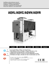
The figure shows the fields reported on the unit dataplate :
A - Trademark
B - Model
B1 - Code
C - Serial number
D - Capacity in cooling
E - Capacity in heating (heat pump)
F - Power input in cooling
G - Power input in heating (heat pump)
H - Reference standard
I - Power supply
L - Maximum absorbed current
M - Refrigerant type and charge weight
N - Unit weight
O - Sound pressure level at 1 metre
P - IP protection level
Q - Maximum pressure - high pressure side
R - Maximum pressure - low pressure side
S - PED certification body
This manual and the wiring diagram supplied with the unit must be kept in a dry place for possible future consultations .
This manual provides information on installation and correct use and maintenance of the unit. Before carrying out installation,
please carefully read all the information contained in this manual, which describes the procedures necessary for correct
installation and use of the unit.
Follow carefully the instructions contained in this manual and respect the safety regulations in force. The unit must be installed
in conformity with the laws in force in the country of use. Unauthorized tampering with the electrical and mechanical equipment
INVALIDATES THE WARRANTY.
Check the electrical specifications given on the dataplate before making the electrical connections. Read the instructions given in
the specific section on electrical connections.
Deactivate the equipment in case of fault or poor operation.
If the unit requires fixings, contact only specialized service centers recognized by the manufacturer and use original spare parts.
The unit must be installed outdoor and connected to a proper air duct distribution system. Any use different from that permitted or
outside the operating limits indicated in this manual is prohibited (unless previously agreed with the firm).
The manufacturer declines any responsability for damage or injury due to non-compliance with the information given in this
manual.
The firm declares that the present unit complies with the requirements of the following directives :
• Machinery directive 2006/42/EC
• Pressure equipment directive (PED) 97/23/EC
• Electromagnetic compatibility directive (EMC) 2004/108/EC
• Low voltage directive (LVD) 2006/95/EC
Codice
Code
B1
Rev
Ferroli Spa
Via Ritonda 78/A
(VR) Italy

5
GENERAL FEATURES
Unit description
This series of packaged air conditioners and heat pumps
(roof top) satisfies the cooling and heating requirements of
medium and large buildings (commercial centres, ipermarkets,
cinemas, outlets, offices, canteens, restaurants ...)
All the units are suitable for outdoor installation and can be
applied to plants realized with various type of air ducts.
Each model is available in various constructive configurations
and can be equipped with a large range of accessories in order
to fit the different installation requirements.
The region in contact with the treated air, easily accessible,
is realized with perfectly washable metal surfaces, externally
insulated in order to minimize the thermal losses and to avoid
condensate generation both on the internal part and the
external part of the structure.
The refrigerant circuit, contained in a compartment protected by
the air flow to simplify the maintenance operations, is equipped
with scroll compressors mounted on damper supports. Each
compressor is placed on an independent refrigerant circuit in
order to keep a constant ratio between the sensible cooling
power and total cooling power also at partial loads and to
guarantee a better treatment of the air besides a greater
reliability.
Each refrigerant circuit is equipped with thermostatic expansion
valves, reverse cycle valve, axial fans with safety protection
grilles, finned coils made of copper pipes and aluminium
louvered fins and high and low pressure switches.
All the units are provided with a phase presence and correct
sequence controller device.
All the units are accurately built and individually tested in the
factory. Only electric, aeraulic and hydraulic connections are
required for installation.
Unit identification code
The codes that identify the units and the meaning of the letters used are described below.
RFA PC 90.2 VB AB 0M5
Unit type
PC - Packaged unit operating
as heat pump (reversible on the
refrigerant circuit)
Power supply
5 - 400 V - 3N - 50 Hz
Operating range
M - Medium temperature.
The unit is suitable for tempe-
rate climate regions
Refrigerant type
0 - R410A
Acoustic setting up
AB - Base setting up
AS - Low noise seting up
Constructive configuration
VB - Base version
V1 - 1 damper version
V2 - 2 dampers version
V3 - 3 dampers version
N° compressors
Model

6
GENERAL FEATURES
Description of components
External structure. Basement, supporting structure and
lateral panels are made of galvanized and painted sheet-
steel (colour RAL 7035) to guarantee good resistance to
atmospheric agents.
The inspection panels are all easily removable by means of
¼ turn locks in order to allow total accessibility to the internal
components. The area in contact with the treated air is realized
with galvanized sheet-steel to guarantee proper cleaning and
is externally insulated by means of foam panels and double
panels with interposed an appropriate thermo acoustic
absorber layer in class 1.
External fan section. It is realized by axial fans with alluminium
sickle profiled blades, placed in a galvanized and painted
sheet-steel nozzle, equipped with a safety protection grille and
directly coupled to external rotor motors with intenal thermal
protection. The fans rotational speed is modulated continuosly
by a phase cut device (option) that allow to control the
condensing pressure (in cooling) and the evaporation pressure
(in heating) according to the value read by the temperature
probe placed on the liquid line.
Internal fan section. It is realized by a couple of centrifugal
fans with double aspiration with forward curved blades
balanced both statically and dynamically according to ISO
1940 standards, grade 6.3. The screw, the impeller, and the
frame are realized with galvanized sheet-steel, while the shaft
is made of C40 steel. The fan is coupled by means of belt and
pulleys to a three phase asynchronous 4-poles electrical motor
connected to an appropriate belt tightening slide, with IP55
protection rating, F insulation class, and suitable for continuous
service (S1) with enough heating margins in case of overloads
of limited extent. For powers equal to or greater than 4 kW the
units are equipped as standard with star-delta starter in order
to reduce the starting current and to ensure longer life of the
transmission. The pulley installed on the motor is a variable
diameter type pulley, and allows, within certain limits, to adjust
the rotational speed of the fan to obtain the desired air flow and
available head values.
Return air fan section. It is realized by a couple of centrifugal
fans with double aspiration with forward curved blades
balanced both statically and dynamically according to ISO
1940 standards, grade 6.3. The screw, the impeller, and the
frame are realized with galvanized sheet-steel, while the shaft
is made of C40 steel. For the models of frame 1 and 2 the
fan is directly coupled to a 2 speed electrical motor (star or
delta connection). For the models of frame 3 the fan is coupled
by means of belt and pulleys to an electrical motor connected
to an appropriate belt tightening slide. The pulley installed on
the motor is a variable diameter type pulley, and allows, within
certain limits, to adjust the rotational speed of the fan to obtain
the desired air flow and available head values.
Filtering section. All the units are equipped with waved type
filter cells realized with a galvanized sheet metal frame, an
electrically welded galvanized steel wire protective screen
and a reusable filter element made of polyester fiber stiffened
with synthetic resins. The filter cells have G4 efficiency
class according to standard CEN-EN 779 (Eurovent EU4
classification - 90% average weighted efficiency) and class 1
flame resistance. The filter cells are easily accessible for the
periodic cleaning and inspection operations. Once the advised
final pressure drop has been reached, the synthetic fiber can be
partially reused after treating with warm water and detergents.
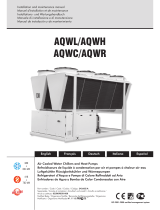
Refrigerant circuit. It is contained inside a compartment
separated from the air flow to simplify maintenance and control
operations.
The ermetic scroll compressors (1) are mounted on damper
supports and are protected against overtemperatures and
overcurrents. They are equipped with an electrical heater,
that is activated when the compressor turns off, to keep the
compressor crankcase oil temperature high enough to prevent
migration of refrigerant during winter stops and to evaporate
any liquid present in the crankcase, in order to prevent possible
liquid rushes on starting (only heat pump models).

7
GENERAL FEATURES
The internal side heat exchanger (user side) (2) is a finned
coil realized with grooved copper pipes and aluminium fins
with notched profile to increase the heat exchange coefficient.
To avoid condensate drag, the frontal crossing air velocity
don't exceed 2,7 m/s, also with the maximum air flow rate
configuration and in the least favourable thermohygrometric
conditions. For the condensate drainage there is a stainless
steel drain tray with inclined bottom, equipped with threaded
connector for the discharge.
The external side heat exchanger (source side) (3) is a
finned coil realized with grooved copper pipes and aluminium
fins with notched profile.
The expansion device (4), a thermostatic expansion valve with
external equalizer , allow the unit to adjust itself to the different
operating conditions keeping steady the set superheating.
The presence in each refrigerant circuit of two valves (one
for the cooling mode and one for the heating mode) allow
to optimize the adjustment of each valve and to obtain the
maximum efficiency.
Each refrigerant circuit contains moreover solid core hermetic
filter dryer (5) to restrain impurity and moisture residuals that
could be present in the circuit, liquid separator (6) placed on
the inlet pipe to protect the compressor against liquid returns,
liquid and humidity indicator (7) to detect the presence of
liquid before each thermostatic valve and allow to verify the
presence of humidity inside the refrigerant, shut off valves
(8) upstream and downstream of each external coil to allow to
stock all the refrigerant inside the coils (pump down) and permit
to execute maintenance operations on the refrigerant circuit
without discharging it, high and low pressure switches in
order to assure the compressor to operate inside the permitted
limits, 4 way reverse cycle valve (9) to allow operating
mode change reversing the refrigerant flow (only heat pump
models) and pressure connections SAE 5/16” - UNF 1/2” -
20 equipped with pin, gasket and blind nut, as required for the
use of R410A refrigerant (they allow the complete check of
the refrigerant circuit: compressor inlet pressure, compressor
outlet pressure and thermostatic valve upstream pressure).
Electrical panel. It contains all the power, control and security
components necessary to guarantee the unit to work properly.
The unit is managed by a microprocessor controller to which all
the electrical loads and the control devices are connected. The
user interface, accessible removing the protection panel of the
electrical board, allow to view and to modify, if necessary, all
the parameters of the unit.
All the units are supplied with an outdoor temperature sensor,
already installed on the unit.
Control system
The unit is managed by a microprocessor controller to which,
through a board placed inside the electrical panel, all the
electrical loads and the control devices are connected. The
user interface, accessible removing the protection panel of
the electrical board, is realized by a display and two buttons
that allow to view and, if necessary, modify all the operating
parameters of the unit.
Are available, as accessories, a remote control, that reports all
the functionalities of the user interface placed on the unit, or a
remote thermostat.
The main functions available are :
- treated air temperature management (through set point
adjustment)
- treated air humidity management (only with enthalpic free
cooling option)
- treated air quality management (CO
2
)
- thermal or enthalpic (option) free cooling
- external fan management by means of continuos rotational
speed control (option)
- internal fan management
- return air fan management
- integrative heating sources management (electrical heater
coil, hot water coil, gas heating module)
- defrost cycle management
- dampers management (outdoor air, return air and expulsion
air)
- compressor and internal fan operating hours recording
- serial communication through Modbus protocol
- remote on-off
- remote cooling-heating
- active alarms visualization
- general alarm digital output
6
8
5
4
7
9
3
1

8
Constructive configurations
GENERAL FEATURES
Base version - VB
Each model can be supplied in different constructive
configurations in order to satisfy the application requirements
that can be necessary for the plants. The various versions,
obtained adding to the base version some modules, are always
supplied already assembled, wired and tested in the factory.
All the versions can be arranged with standard air flow position
(frontal for the models of frame 1 and 2 and upwards for the
models of frame 3) or with downwards air flow position.
The dotted components are accessories.
It only allows to operate with all return air.
It contains the standard filtering section and the air-
refrigerant exchange coil that allows the heating, cooling and
dehumidification processes to be performed.
It is possible to add a further heating section (hot water coil or
electrical heater coil) and the droplets separator.
Instead of such heating section it is possible to add a gas
heating module, placed between the filtering section and the
air-refrigerant exchange coil.
1 damper version - V1
It allows to operate with a percentage of outdoor fresh air,
adjustable manually setting the damper placed on the adding
module. The outdoor air inlet is equipped with a rain protection
cap and a metal safety grille. The expulsion from the conditioned
ambient of an air flow rate equal to the outdoor fresh air flow
rate must be realized independently from the unit by means of
overpressure openings or other extraction devices.
In the adding module can be placed various type of special
filters in order to complete the standard filtering section.
Also in this version it is possible to add a further heating
section (hot water coil or electrical heater coil) and the droplets
separator.
Instead of such heating section it is possible to add a gas
heating module, placed between the filtering section and the
air-refrigerant exchange coil.
Downstream the internal fans, air flow silencers can be installed
to reduce the noise transmitted to the conditioned ambients
through the air ducts (only for the models of frame 1 and 2).
RETURN AIR AIR FLOW
AIR FLOWRETURN AIR
OUTDOOR AIR

9
GENERAL FEATURES
2 dampers version - V2
The presence of two motorized dampers managed by the
controller of the unit allows to operate with a minimum
percentage of outdoor fresh air (adjustable through the user
interface) and to perform thermal free cooling.
The outdoor air inlet, equipped with a rain protection cap and
a metal safety grille, is designed for 100% of the total air flow
rate and allows to operate in free cooling with all outdoor air.
The expulsion from the conditioned ambient of an air flow
rate equal to the outdoor fresh air flow rate must be realized
independently from the unit by means of overpressure
openings or other extraction devices.
In the adding module can be placed various type of special
filters in order to complete the standard filtering section.
It is possible to add a further heating section (hot water coil
or electrical heater coil) and the droplets separator. Instead of
such heating section it is possible to add a gas heating module,
placed between the filtering section and the air-refrigerant
exchange coil.
It is also possible to perform enthalpic free cooling by means of
the installation of the humidity sensors.
Downstream the internal fans, air flow silencers can be installed
to reduce the noise transmitted to the conditioned ambients
through the air ducts (only for the models of frame 1 and 2).
3 dampers version - V3
The presence of three motorized dampers managed by
the controller of the unit allows to operate with a minimum
percentage of outdoor fresh air (adjustable through the user
interface), to perform thermal free cooling and to manage the
air expulsion.
The outdoor air inlet, equipped with a rain protection cap and
a metal safety grille, is designed for 100% of the total air flow
rate and allows to operate in free cooling with all outdoor air.
The expulsion from the conditioned ambient of an air flow rate
equal to the outdoor fresh air flow rate is realized through the
return air fan and the expulsion damper placed inside the unit.
In the adding module can be placed various type of special
filters in order to complete the standard filtering section.
Also in this version it is possible to add a further heating
section (hot water coil or electrical heater coil) and the droplets
separator. Instead of such heating section it is possible to add
a gas heating module, placed between the filtering section and
the air-refrigerant exchange coil.
It is also possible to perform enthalpic free cooling by means of
the installation of the humidity sensors.
Downstream the internal fans, air flow silencers can be installed
to reduce the noise transmitted to the conditioned ambients
through the air ducts (only for the models of frame 1 and 2).
RETURN AIR
EXPULSION AIR
AIR FLOW
AIR FLOW
RETURN AIR
OUTDOOR AIR
OUTDOOR AIR

10
GENERAL FEATURES
Options
Constructive
configuration
VB - Base version It only allows to operate with all return air.
V1 - 1 damper version It allows to operate with a fixed percentage of outdoor fresh air, manually set.
V2 - 2 dampers version
It allows to operate with a variable percentage of outdoor fresh air, adjusted by
the unit controller according to free cooling and air quality control algorythms.
V3 - 3 dampers version
It allows to operate with a variable percentage of outdoor fresh air, adjusted by
the unit controller according to free cooling and air quality control algorythms.
Moreover it manages the expulsion of an air flow rate equal to the outdoor fresh
air flow rate.
Air flow
position
Standard
(frontal or upwards)
For the models of frame 1 and 2 the standard position is frontal while for the
models of frame 3 the standard position is upwards.
Downwards It is available for all the models and it allows a more compact installation.
Internal fan
Standard
In order to adjust the performances of the internal fan to the air flow rate and
available head values required, for each model are available three type of inter-
nal fan that are different for pulleys used, electrical motor installed power and in
some cases for the kind of fan used.
The pulley installed on the electrical motor is a variable diameter type pulley
and allows, within certain limits, to adjust the performance curve of the fan to
the characteristic curve of the plant.
Upsized
Reduced
Heating
integration
Hot water coil
2 or 3 rows
with pipes
It performs the heating function (as heat pump integration or replacement), the
post heating function (in cooling mode) and the ice protection function. It is
equipped with automatic air vent, drain valve, shut off ball valves at the inlet and
outlet, safety valve (6 bar) and stainless steel condensate tray.
The ball type motorized 3 way valve is managed by the unit controller according
to an on-off logic.
Hot water coil
2 or 3 rows
with 3 way valve
Electrical heater coil
standard or upsized
It performs the heating function (as heat pump integration or replacement), the
post heating function (in cooling mode) and the ice protection function. It is
equipped with safety thermostat and is protected against overcurrents by me-
ans of fuses placed inside the electrical panel.
Condensing
gas heating module
standard or upsized
It performs the heating function (as heat pump replacement) and the ice pro-
tection function. The stainless steel air-fumes exchanger is coupled with a mo-
dulating premixed burner that allows to adjust the power supplied inside a wide
operating range and to maximize the exploitation of the fumes condensing heat
also at part loads.
Low noise acoustic setting up
It allows to reduce the noise emissions produced by the unit through the insula-
tion of the walls of the compartment that contains the refrigerant circuit and the
use of sound absorbent jackets on the compressors. Such setting up includes
also the modulating control of the external fans.
Air flow silencers
They allow to reduce the noise transmitted to the conditioned ambients through
the air ducts. They are realized by mineral wool acoustic baffles with fiberglass
coating placed downstream the centrifugal internal fan.
They are available only for the models of frame 1 and 2 with standard "Air flow
position" option.
External fans control
The modulating control of the external fans allows to operate with low outdoor
temperatures in cooling and high outdoor temperatures in heating and permits
to reduce noise emissions in such operating conditions.
The fans rotational speed is modulated continuosly by a phase cut device that
allow to control the condensing pressure (in cooling) and the evaporation pres-
sure (in heating) according to the value read by the temperature probe placed
on the liquid line.

11
GENERAL FEATURES
Accessories
Spring vibration dampers
Allow to reduce the transmission to the unit support plane of the mechanical vibrations generated by the com-
pressor and by the fans in their normal operating mode.
In order to keep the insulation degree higher than 90%, the number and the features of the dampers are different
according to the model and the constructive configuration.
When this accessory is chosen, flexible connections must be used on all the aeraulic and hydraulic connections.
Moreover the height of the dampers, fitted between the basement of the unit and the support plane, must be
taken into account to design correctly the air ducts.
External coils
protection grilles
Protect the external surface of the finned coils.
High and low
pressure gauges
Each refrigerant circuit is equipped with two analog gauges, placed inside the refrigerant circuit compartment,
that detect the pressure in the compressor inlet and outlet pipes.
Remote control
It is suitable for wall mounting and reports all the functions available on the user interface normally placed on the
unit. It therefore allows the complete remote control of the unit.
Remote thermostat
It is suitable for wall mounting and consists of a simplified remote user interface compared to the standard one
normally placed on the unit. It allows to select the operating mode, set a deviation respect to the active set-point
and visualize the operating status and the presence of active alarms.
Modbus serial interface
on RS485
It allows to communicate with the unit controller and to view the operating conditions of the unit through Modbus
communication protocol. The RS485 serial line ensures the signal quality up to distances of about 1200 metres
(that can be extended by means of proper repeaters).
Programmer clock
It allows the unit to be turned on and off according to a set program, through the digital input available on the unit
wiring board (remote on-off).
Phase sequence and
voltage controller
It checks not only the presence and correct order of the power supply phases but also the voltage level on each
phase and avoid the unit to operate with voltage levels outside the permitted limits.
Roof curb
Metal structure to be applied to the units with downwards air flow in order to facilitate the installation and to
guarantee a perfect tight between the air duct and the unit itself.
The correct positioning of the roof curb requires an accurate finishing of the installation area.
Enthalpic free cooling
It allows to increase the seasonal efficiency of the unit through a more extended
and optimized use of the free cooling function, obtained considering the enthal-
pies of the outdoor and of the return air instead of the simple temperatures. The
measure of the relative humidity (of the outdoor and of the return air), necessary
for the enthalpy calculation, is realized through two capacitive humidity sensors.
Air quality control (CO
2
)
It manages the motorized dampers opening (in the versions in which they are
present) according to the CO
2
percentage of the ambients to be conditioned,
increasing, if necessary, the outdoor fresh air percentage.
If the (thermal or enthalpic) free cooling function is enabled the dampers ope-
ning is obtained by the combination of the two control logics.
Special filters
To complete the standard filtering section it is possible to add rigid pocket fil-
ters of various efficiency (from F6 to F9 according to EN 779) or active carbon
filters with F7 filtering class. The filter supporting frame is studied to guarantee
a perfect tight and an easy lateral extraction of the filters for the maintenance
operations.
Available only for the units with V1, V2 or V3 constructive configuration.
Filters differential pressure switch
It detects the pressure difference between upstream and downstream the filte-
ring section. When the pressure drops exceed the maximum permitted value
(factory set according to the type of filters fitted on the unit) the pressure switch
stops the unit avoiding it to work with an air flow rate excessively low compared
to the one required.
Droplets separator
It is reccomended for units that require air flow rates particularly high compared
to the standard air flow rate and when the medium crossing air velocity is higher
than 2,7 m/s.
It avoids the condensate droplets that are generated on the exchange coil du-
ring cooling mode operation to be dragged. It is equipped with stainless steel
condensate tray with inclined bottom and threaded connector for the discharge.
It is never required if the hot water coil is mounted.

12
TECHNICAL DATA AND PERFORMANCES
Frame
1 2 3
Model
35.1 45.1 55.1 70.2 90.2 110.2 140.2 180.2 220.2
U.M.
Powwer supply
400 - 3N - 50 400 - 3N - 50 400 - 3N - 50 V-ph-Hz
Technical data
Refrigerant
Type
R410A R410A R410A R410A R410A R410A R410A R410A R410A -
Compressor
Type
scroll scroll scroll scroll scroll scroll scroll scroll scroll -
Quantity
1 1 1 2 2 2 2 2 2 n°
Refrigerant circuits
1 1 1 2 2 2 2 2 2 n°
Power steps of the unit
0 - 100 0 - 100 0 - 100 0 - 50 - 100 0 - 50 - 100 0 - 50 - 100 0 - 50 - 100 0 - 50 - 100 0 - 50 - 100
%
Oil charge compressor 1
3,25 3,25 4,70 3,25 3,25 4,70 6,80 6,30 6,30 kg
Oil charge compressor 2
- - - 3,25 3,25 4,70 6,80 6,30 6,30 kg
Internal side heat exchanger (plant)
Type
finned
coil
finned
coil
finned
coil
finned
coil
finned
coil
finned
coil
finned
coil
finned
coil
finned
coil
-
Quantity
1 1 1 1 1 1 1 1 1 n°
Frontal surface
0,84 1,08 1,32 1,26 1,62 1,98 2,52 3,24 3,78 m
2
External side heat exchanger
Type
finned
coil
finned
coil
finned
coil
finned
coil
finned
coil
finned
coil
finned
coil
finned
coil
finned
coil
-
Quantity
1 1 1 2 2 2 2 2 2 n°
Frontal surface
1,96 1,96 1,96 1,96 1,96 1,96 4,00 4,00 4,00 m
2
External section fans
Type
axial axial
axial
axial
axial
axial
axial axial
axial -
Quantity
2 2 2 4 4 4 4 4 4 n°
Diameter
630 630 630 630 630 630 800 800 800 mm
Maximum rotational speed
900 900 900 900 900 900 900 900 900 rpm
Total installed power
1,6 1,6 1,6 3,2 3,2 3,2 8,0 8,0 8,0 kW
Internal section fans
Type
centrifugal centrifuga centrifuga centrifuga centrifuga centrifuga centrifuga centrifuga centrifuga
-
Quantity
2 2 2 2 2 2 2 2 2 n°
MINIMUM air flow rate
5200 6800 8400 9100 12100 14000 18500 23500 28500 m
3
/h
STANDARD air flow rate
6200 8100 10000 11000 14500 17000 22500 29000 35000 m
3
/h
MAXIMUM air flow rate
7200 9400 11700 13000 17000 20100 26500 34000 41000 m
3
/h
STANDARD available static head 200 200 200 200 200 200 200 200 200 Pa
Absorbed power
1,4 1,8 2,2 3,5 4,3 5,1 6,6 8,7 10,5 kW
Installed power
1,5 2,2 2,2 4,0 5,5 5,5 11,0 11,0 18,4 kW

13
TECHNICAL DATA AND PERFORMANCES
NOMINAL performances
PC
Cooling A35A27 ( source : air in 35°C d.b. / plant : air in 27°C d.b. 19°C w.b. )
Total cooling capacity 35,5 46,3 57,7 71,0 92,3 113,0 142,0 184,0 226,0
kW
RST* 0,70 0,70 0,70 0,70 0,70 0,70 0,70 0,70 0,70
-
Power input 10,9 14,0 17,7 22,5 28,8 36,6 46,6 59,5 73,7
kW
EER 3,26 3,31 3,26 3,16 3,20 3,09 3,05 3,09 3,07
-
Air flow rate plant side 6200 8100 10000 11000 14500 17000 22500 29000 35000
m
3
/h
Available static head plant side 200 200 200 200 200 200 200 200 200
Pa
Heating A7A20 ( source : air in 7°C d.b. 6°C w.b. / plant : air in 20°C d.b. )
Heating capacity 36,7 47,8 59,5 73,9 95,9 118,0 148,0 192,0 236,0
kW
Power input 11,2 14,4 18,2 23,0 29,5 37,5 47,7 60,9 75,5
kW
COP 3,28 3,32 3,27 3,21 3,25 3,15 3,10 3,15 3,13
-
Air flow rate plant side 6200 8100 10000 11000 14500 17000 22500 29000 35000
m
3
/h
Available static head plant side 200 200 200 200 200 200 200 200 200
Pa
Data declared according to EN 14511. The values are referred to units without options and accessories operating with 100% return air.
* RST = ratio between sensible cooling capacity and total cooling capacity.
Frame
1 2 3
Model
35.1 45.1 55.1 70.2 90.2 110.2 140.2 180.2 220.2
U.M.
Power supply
400 - 3N - 50 400 - 3N - 50 400 - 3N - 50 V-ph-Hz
The graphs reported below allow to get the corrective factors to be applied to the performances with standard air flow rate in order
to obtain the real performances with the selected air flow rate.
0,85
0,90
0,95
1,00
1,05
1,10
1,15
0,80 0,85 0,90 0,95 1,00 1,05 1,10 1,15 1,20
COOLING OPERATING MODE
Performances with NOT STANDARD air flow rate
0,85
0,90
0,95
1,00
1,05
1,10
1,15
0,80 0,85 0,90 0,95 1,00 1,05 1,10 1,15 1,20
HEATING OPERATING MODE
Heating capacity
Total cooling capacity
Power input
RST
Power input
Air flow rate / STANDARD air flow rate Air flow rate / STANDARD air flow rate

14
0,4
0,6
0,8
1,0
1,2
1,4
1,6
1,8
2,0
15 20 25 30 35 40 45 50
0,5
0,6
0,7
0,8
0,9
1,0
1,1
1,2
1,3
1,4
1,5
15 20 25 30 35 40 45 50
0,5
0,6
0,7
0,8
0,9
1,0
1,1
1,2
1,3
1,4
1,5
15 20 25 30 35 40 45 50
TECHNICAL DATA AND PERFORMANCES
COOLING performances
The graphs allow to get the corrective factors to be applied to the
nominal performances in order to obtain the real performances in the
selected operating conditions.
The reference nominal condition is : A35A27
source : air in 35°C d.b. / plant : air in 27°C d.b. 19°C w.b.
Inlet w.b. temperature plant side :
Cooling capacity
Inlet air temperature d.b. [°C]
Inlet air temperature d.b. [°C]
Inlet air temperature d.b. [°C]
Power input
EER
A
B
C
D
A
B
C
D
A
B
C
D
0,5
0,6
0,7
0,8
0,9
1,0
1,1
1,2
1,3
1,4
1,5
15 20 25 30 35 40 45 50
RST
Inlet air temperature d.b. [°C]
A
B
C
D
A = 27°C
B = 23°C
C = 19°C
D = 15°C
E = 11°C
E
E
E
E

15
TECHNICAL DATA AND PERFORMANCES
0,4
0,6
0,8
1,0
1,2
1,4
1,6
1,8
2,0
-15 -10 -5 0 5 1 0 15 20
0,5
0,6
0,7
0,8
0,9
1,0
1,1
1,2
1,3
1,4
1,5
-15 -10 -5 0 5 1 0 15 20
0,5
0,6
0,7
0,8
0,9
1,0
1,1
1,2
1,3
1,4
1,5
-15 -10 -5 0 5 1 0 15 20
HEATING performances
Heating capacity
Inlet air temperature w.b. [°C]
Inlet air temperature w.b. [°C]
Inlet air temperature w.b. [°C]
Power input
COP
A
B
C
D
A
B
C
D
A
B
C
D
E
E
E
The graphs allow to get the corrective factors to be applied to the
nominal performances in order to obtain the real performances in the
selected operating conditions.
The reference nominal condition is : A7A20
source : air in 7°C d.b. 6°C w.b. / plant : air in 20°C d.b.
Inlet d.b. temperature plant side :
A = 28°C
B = 24°C
C = 20°C
D = 16°C
E = 12°C

16
TECHNICAL DATA AND PERFORMANCES
Hot water coil performances
2 ROWS
Water : 60 - 40 °C
Air flow rate
Minimum Standard Maximum
Model
T
inlet air
Capacity
Water
flow rate
Water
pressure
drops
Capacity
Water
flow rate
Water
pressure
drops
Capacity
Water
flow rate
Water
pressure
drops
[°C] [kW] [l/h] [kPa] [kW] [l/h] [kPa] [kW] [l/h] [kPa]
35.1
10 40,8 1771 4 45,7 1985 5 50,1 2176 6
15 33,3 1448 2 38,3 1664 4 42,7 1855 4
20 25,4 1102 1 29,4 1279 2 33,3 1448 2
45.1
10 52,7 2292 4 59,2 2571 5 64,8 2817 5
15 43,0 1869 2 49,4 2147 4 55,2 2400 4
20 32,6 1417 1 37,8 1644 2 42,8 1861 2
55.1
10 64,7 2812 4 72,7 3157 5 79,6 3457 5
15 52,7 2290 2 60,5 2631 4 67,8 2946 4
20 39,8 1731 1 46,2 2008 2 52,3 2274 2
70.2
10 70,8 3075 14 80,2 3484 18 88,8 3858 20
15 60,8 2641 11 68,8 2991 13 76,2 3309 16
20 50,8 2208 8 57,5 2498 10 63,6 2762 12
90.2
10 92,9 4038 14 104,5 4541 17 115,1 5003 20
15 79,8 3467 11 89,7 3896 13 98,7 4290 16
20 66,7 2898 8 74,9 3253 10 82,4 3579 11
110.2
10 110,2 4788 13 124,4 5404 16 137,4 5969 19
15 94,6 4111 10 106,7 4637 12 117,8 5118 14
20 79,1 3436 7 89,1 3871 8 98,3 4269 11
140.2
10 141,5 6150 14 160,4 6968 18 177,6 7716 20
15 121,5 5282 11 137,6 5982 13 152,3 6618 16
20 101,6 4416 8 115,0 4996 10 127,1 5524 12
180.2
10 185,9 8076 14 209,0 9082 17 230,3 10006 20
15 159,6 6934 11 179,3 7792 13 197,5 8580 16
20 133,4 5796 8 149,7 6506 10 164,7 7158 11
220.2
10 220,4 9576 13 248,7 10808 16 274,7 11938 19
15 189,2 8222 10 213,4 9274 12 235,6 10236 14
20 158,2 6872 7 178,2 7742 8 196,5 8538 11
2 ROWS
Water : 80 - 60 °C
Air flow rate
Minimum Standard Maximum
Model
T
inlet air
Capacity
Water
flow rate
Water
pressure
drops
Capacity
Water
flow rate
Water
pressure
drops
Capacity
Water
flow rate
Water
pressure
drops
[°C] [kW] [l/h] [kPa] [kW] [l/h] [kPa] [kW] [l/h] [kPa]
35.1
10 65,3 2867 8 73,1 3212 10 80,4 3532 12
15 59,2 2599 7 66,3 2912 8 72,9 3202 10
20 53,2 2335 6 59,5 2616 7 65,5 2875 8
45.1
10 84,7 3722 8 94,9 4167 10 104,2 4578 11
15 76,8 3374 6 86,0 3777 8 94,5 4150 10
20 69,0 3031 6 77,2 3392 7 84,8 3726 8
55.1
10 104,2 4577 7 116,6 5121 10 128,1 5625 11
15 94,5 4149 6 105,7 4642 8 116,1 5099 10
20 84,8 3727 5 94,9 4169 6 104,2 4578 7
70.2
10 110,7 4864 29 125,9 5531 36 139,8 6141 43
15 100,6 4419 24 114,4 5025 30 127,0 5579 36
20 90,6 3979 20 103,0 4524 25 114,3 5023 30
90.2
10 145,6 6396 29 164,3 7217 35 181,5 7972 42
15 132,3 5811 24 149,3 6556 30 164,9 7242 35
20 119,1 5231 20 134,4 5902 25 148,4 6518 30
110.2
10 172,6 7581 26 195,5 8587 32 216,5 9510 38
15 156,8 6887 22 177,6 7800 28 196,7 8638 32
20 141,2 6200 18 159,8 7021 23 177,0 7775 28
140.2
10 221,4 9728 29 251,8 11062 36 279,6 12282 43
15 201,2 8838 24 228,8 10050 30 254,0 11158 36
20 181,1 7958 20 206,0 9048 25 228,7 10046 30
180.2
10 291,2 12792 29 328,6 14434 35 363,0 15944 42
15 264,5 11622 24 298,5 13112 30 329,7 14484 35
20 238,2 10462 20 268,7 11804 25 296,8 13036 30
220.2
10 345,2 15162 26 390,9 17174 32 433,0 19020 38
15 313,6 13774 22 355,1 15600 28 393,3 17276 32
20 282,3 12400 18 319,7 14042 23 354,0 15550 28

17
TECHNICAL DATA AND PERFORMANCES
3 ROWS
Water : 80 - 60 °C
Air flow rate
Minimum Standard Maximum
Model
T
inlet air
Capacity
Water
flow rate
Water
pressure
drops
Capacity
Water
flow rate
Water
pressure
drops
Capacity
Water
flow rate
Water
pressure
drops
[°C] [kW] [l/h] [kPa] [kW] [l/h] [kPa] [kW] [l/h] [kPa]
35.1
10 85,7 3765 19 97,7 4293 24 109,1 4791 30
15 77,8 3419 17 88,8 3899 20 99,1 4351 25
20 70,1 3080 13 79,9 3511 17 89,2 3918 20
45.1
10 111,5 4899 19 127,1 5581 24 141,7 6224 29
15 101,3 4449 16 115,4 5068 20 128,7 5652 24
20 91,2 4007 13 103,9 4564 17 115,8 5088 20
55.1
10 137,3 6032 19 156,4 6868 24 174,3 7656 29
15 124,7 5478 16 142,0 6237 19 158,3 6952 24
20 112,3 4934 13 127,8 5616 17 142,5 6259 20
70.2
10 146,0 6413 70 169,4 7440 90 191,2 8399 112
15 132,8 5833 59 154,0 6766 77 173,9 7638 95
20 119,8 5261 49 138,9 6102 64 156,8 6888 79
90.2
10 192,8 8468 70 221,6 9736 89 248,7 10924 109
15 175,3 7701 59 201,6 8854 76 226,1 9934 92
20 158,1 6945 49 181,8 7984 62 203,9 8957 77
110.2
10 227,5 9992 64 262,7 11538 82 295,6 12984 101
15 206,9 9087 54 238,9 10492 70 268,8 11807 85
20 186,6 8196 46 215,4 9462 58 242,4 10646 71
140.2
10 292,0 12826 70 338,7 14880 90 382,4 16798 112
15 265,6 11666 59 308,1 13532 77 347,8 15276 95
20 239,5 10522 49 277,8 12204 64 313,6 13776 79
180.2
10 385,5 16936 70 443,3 19472 89 497,3 21848 109
15 350,6 15402 59 403,1 17708 76 452,3 19868 92
20 316,2 13890 49 363,5 15968 62 407,8 17914 77
220.2
10 455,0 19984 64 525,3 23076 82 591,2 25968 101
15 413,7 18174 54 477,7 20984 70 537,6 23614 85
20 373,1 16392 46 430,8 18924 58 484,7 21292 71
3 ROWS
Water : 60 - 40 °C
Air flow rate
Minimum Standard Maximum
Model
T
inlet air
Capacity
Water
flow rate
Water
pressure
drops
Capacity
Water
flow rate
Water
pressure
drops
Capacity
Water
flow rate
Water
pressure
drops
[°C] [kW] [l/h] [kPa] [kW] [l/h] [kPa] [kW] [l/h] [kPa]
35.1
10 55,6 2417 10 63,2 2745 12 70,3 3054 14
15 47,9 2081 7 54,4 2362 10 60,4 2626 11
20 40,0 1737 6 45,6 1982 7 50,6 2201 8
45.1
10 72,3 3141 10 82,0 3564 12 91,2 3962 14
15 62,2 2705 7 70,6 3067 10 78,4 3407 11
20 51,9 2253 5 59,2 2572 7 65,7 2854 8
55.1
10 88,9 3865 10 100,9 4384 12 112,1 4871 14
15 76,6 3328 7 86,8 3771 8 96,4 4187 11
20 63,7 2769 5 72,8 3161 7 80,7 3506 8
70.2
10 95,8 4164 36 110,7 4812 47 124,6 5416 56
15 82,8 3599 28 95,7 4156 36 107,6 4675 44
20 69,9 3039 20 80,6 3504 26 90,6 3937 32
90.2
10 126,4 5491 36 144,8 6291 46 162,0 7038 55
15 109,2 4745 28 125,0 5432 35 139,8 6074 43
20 92,1 4004 20 105,4 4578 26 117,7 5114 31
110.2
10 149,2 6484 32 171,7 7458 42 192,6 8369 52
15 129,0 5603 25 148,2 6441 32 166,2 7223 40
20 108,8 4729 19 124,9 5429 24 140,0 6082 29
140.2
10 191,7 8328 36 221,5 9624 47 249,3 10832 56
15 165,7 7198 28 191,3 8312 36 215,2 9350 44
20 139,8 6078 20 161,3 7008 26 181,2 7874 32
180.2
10 252,7 10982 36 289,5 12582 46 323,9 14076 55
15 218,4 9490 28 250,0 10864 35 279,6 12148 43
20 184,3 8008 20 210,7 9156 26 235,4 10228 31
220.2
10 298,4 12968 32 343,3 14916 42 385,2 16738 52
15 257,9 11206 25 296,5 12882 32 332,4 14446 40
20 217,7 9458 19 249,9 10858 24 279,9 12164 29

18
0
50
100
150
200
250
300
350
400
450
500
550
600
5000 6000 7000 8000 9000 10000 11000 12000
TECHNICAL DATA AND PERFORMANCES
Plant side aeraulic performances
Available static head - unit without options
The graphs are referred to units operating with air at the temperature of 20°C (density 1,20 kg/m
3
).
Air flow rate [ m
3
/h ]
Available static head [ Pa ]
Upsized
35.1
Standard
Reduced
The internal fan must be selected according to the required air ow rate and to the required total head.
The required total head must be calculated as sum of the required available head and of the pressure drops of the options or
accessories applied to the unit. Such pressure drops must be calculated according to the required air ow rate using the graphs
reported in the present manual.
The graphs reported below show the characteristic aeraulic curves of each model. Such curves are obtained subtracting to the
head supplied by the fan the pressure drops of the standard lters (G4), the pressure drops of the internal coil and the pressure
drops of the internal structure of the unit.
N.B. The curves are referred to units with BASE constructive conguration (VB) without options or accessories and with
dry internal coil.
Model
35.1 - 45.1 - 55.1 70.2 - 90.2 - 110.2 140.2 - 180.2 - 220.2
U.M.
Standard Upsized Standard Upsized Standard Upsized
Nominal heating capacity
max 44,8 54,0 93,4 145,0 186,8 290,0 kW
min 15,5 16,3 31,5 46,3 63,0 92,6 kW
Efciency
max 94,3 93,1 95,3 93,5 95,3 93,5 %
min 105,0 105,0 105,0 105,2 105,0 105,2 %
Gas input
(15°C – 1013 mbar)
max 5,03 6,14 10,37 16,40 20,74 32,8 m
3
/h
min 1,57 1,64 3,17 4,66 6,34 9,32 m
3
/h
Condensate generated 1,45 1,45 2,60 3,87 5,20 7,74 l/h
Available static head exhaust fumes 120 120 120 100 120 100 Pa
Model 35.1 - 45.1 - 55.1 70.2 - 90.2 - 110.2 140.2 - 180.2 - 220.2 U.M.
Standard coil 9,0 18,0 36,0 kW
Upsized coil 18,0 31,5 63,0 kW
The reported data are referred to the module operating with natural gas G20 at 20 mbar supply pressure.
Electrical heater coil performances
Condensing gas heating module performances

19
0
50
100
150
200
250
300
350
400
450
500
550
600
5000 6000 7000 8000 9000 10000 11000 12000
TECHNICAL DATA AND PERFORMANCES
Air flow rate [ m
3
/h ]
Available static head [ Pa ]
Upsized
55.1
Standard
Reduced
The graphs are referred to units operating with air at the temperature of 20°C (density 1,20 kg/m
3
).
0
50
100
150
200
250
300
350
400
450
500
550
600
5000 6000 7000 8000 9000 10000 11000 12000
Air flow rate [ m
3
/h ]
Available static head [ Pa ]
Upsized
45.1
Standard
Reduced

20
0
50
100
150
200
250
300
350
400
450
500
550
600
8000 9000 10000 11000 12000 13000 14000 15000 16000 17000 18000 19000 20000 21000
Air flow rate [ m
3
/h ]
Available static head [ Pa ]
Upsized
70.2
Standard
Reduced
0
50
100
150
200
250
300
350
400
450
500
550
600
8000 9000 10000 11000 12000 13000 14000 15000 16000 17000 18000 19000 20000 21000
TECHNICAL DATA AND PERFORMANCES
Air flow rate [ m
3
/h ]
Available static head [ Pa ]
Upsized
90.2
Standard
Reduced
The graphs are referred to units operating with air at the temperature of 20°C (density 1,20 kg/m
3
).
/