Page is loading ...

Wall hung, fanflue, roomsealed, high efficiency gas boiler
User manual and
Installation instructions
Riva Plus HE ERP
Models G.C. Appl. No.
RIVA PLUS HE 24S ERP 41-583-31 SYSTEM BOILER
RIVA PLUS HE 28S ERP 41-583-32 SYSTEM BOILER

- 2 -
WARNING
Congratulations on your choice.
Riva Plus HE ERP are condensing high efciency sealed chamber fan ue gas boilers. They
are fully electronically controlled and have electronic ignition.
The materials they are made of and the control systems they are equipped with give you
safety, a high level of comfort and energy savings to allow you to get the greatest benet out
of independent heating.
Riva Plus HE ERP allow a higher efciency by reducing the ue gas temperature such that
the water vapour formed during the combustion is condensed out.
This allows a gain of useful heat that otherwise would be lost.
Biasi UK Ltd is a licensed member of the Benchmark Scheme which aims to improve the
standards of installation and commissioning of domestic heating and hot water systems in
the UK and to encourage regular servicing to optimise safety, efciency and performance.
Benchmark is managed and promoted by the Heating and Hot water Industry Council. For
more information visit www.centralheating.co.uk.
DANGER: The indications marked with this symbol must be observed to pre-
vent accidents of mechanical or generic origin (e.g.: Injuries or bruises).
DANGER: The indications marked with this symbol must be observed to pre-
vent accidents of electric origin (electrocution).
DANGER: The indications marked with this symbol must be observed to pre-
vent the risk of re or explosion.
DANGER: The indications marked with this symbol must be observed to pre-
vent accidents of heat origin (burns).
ATTENTION: The indications marked with this symbol must be observed to
prevent malfunctioning and/or damage to materials of the appliance or other
objects.
ATTENTION: The indications marked with this symbol are important informa-
tion that must be carefully read.

- 3 -
WARNING
Remember that...
The manual must be read thoroughly, so that you will be able to use the boiler in a safe
and sensible way and must be carefully kept. It may be necessary for reference in the
future.
The lighting up must be carried out by a competent and responsible engineer.
The manufacturer
• disclaims all liability for any translations of the present manual from which incorrect
interpretation may occur;
• cannot be held responsible for non-observance of instructions contained in this manual
or for the consequences of any procedure not specically described.
Please ensure that the installer has fully completed the Benchmark Checklist on the inside
back pages of the installation instructions supplied with the product and that you have signed
it to say that you have received a full and clear explanation of its operation. The installer is
legally required to complete a commissioning checklist as a means of complying with the
appropriate Building Regulations (England and Wales).
All installations must be notied to Local Area Building Control either directly or through a
Competent Persons Scheme. A Building Regulations Compliance Certicate will then be
issued to the customer who should, on receipt, write the Notication Number on the Bench-
mark Checklist.
This product should be serviced regularly to optimise its safety, efciency and performance.
The service engineer should complete the relevant Service Record on the Benchmark
Checklist after each service.
The Benchmark Checklist will be required in the event of any warranty
Using the boiler...
Before lighting the boiler you are advised to have a Registered Gas Safe Registered
Engineer check that the installation of the gas supply is
• gas-tight;
• of the correct gauge for the ow to the boiler;
• tted with all the safety and control devices required by the current Regulations.
Ensure that
• the Installer has connected and terminated the pressure relief valve in a manner which
allows safe discharge. The manufacturers are not responsible for damage caused by
opening of the pressure relief valve and consequent escape of water, if this is not con-
nected and terminated.
• the installer has connected the condensate outlet to a suitable drain pipe.

- 4 -
WARNING
On detecting the smell of gas:
• do not operate any electrical switches, the telephone or any device that may produce
sparks;
• open the windows and doors at once to create a draught of air which will purge the area;
• shut off the gas cocks;
• get the assistance of a qualied person. Emergency telephone number
Tel 0800 111999.
Do not touch the appliance with parts of the body that are wet or damp and/or bare feet.
Do not block or modify the condensate outlet and pipework.
In case of structural work or maintenance near the ue and ue terminal turn off the
appliance. On completion of the work, have a professionally qualied person check there
efciency.
Repairs (under guarantee) must be carried out only by an approved engineer, using
genuine spare parts. Thus do no more than switching off the boiler yourself (see the in-
structions).
Your boiler allows heating up of water to a temperature less than boiling point therefore it
• must be connected to a central heating system and/or a hot water supply system, com-
patible with its performance and output;
• can be used only for those purposes for which it has been specially designed;
• must not be touched by children or by those unfamiliar with its operation;
• must not be exposed to weather conditions.
During the operation it is quite normal that the boiler produces a white plume of conden-
sation vapour from the ue terminal. This is due to the high efciency of the appliance and
may be particularly evident with low outdoor temperatures.
Safe handling of substances
Biasi products are manufactured in accordance with ISO 9001 and do not, and will not,
contain any hazardous materials or substances such as asbestos, mercury or C.F.C.’s. The
appliance packaging does not contain any substances, which may be considered a hazard
to health.
When handling or lifting always use safe techniques
• Keep your back straight, bend your knees, don't twist.
• Move your feet, avoid bending forwards and side ways and keep the load as close to your
body as possible.
Where possible transport the boiler using a sack truck or other suitable trolly.
Always grip the boiler rmly, and before lifting feel where the weight is concentrated to estab-
lish the centre of gravity, repositioning yourself as necessary.

- 5 -
WARNING
Combustion chamber panels
Material: mineral bres
Known hazards - Some people can suffer reddening and itching of the skin. Fibre entry into
the eye will cause foreign body irritation, which can cause severe irritation to people wearing
contact lenses. Irritation to respiratory tract.
Precautions - Dust goggles will protect eyes. People with a history of skin complaints may
be particularly susceptible to irritation. High dust levels are only likely to arise following harsh
abrasion. In general, normal handling and use will not present high risk. Follow good hygiene
practices; wash hands before, touching eyes, consuming food, drinking or using the toilet.
First aid - Medical attention must be sought following eye contact or prolonged reddening of
the skin.
Sharp Edges
Caution should be taken when handling the boiler to avoid sharp edges on the boiler.
Boiler installation and commissioning tips
The installation must be carried out by a qualied Gas Safe Registered Engineer who will
be responsible for observing the current Regulations and the completion of the Bench-
mark Gas Boiler System Commissioning Checklist, located at the back of this User man-
ual.

- 6 -
WARNING
Abbreviations used in the manual:
C.H. = Central heating
D.H.W. = Domestic hot water
D.C.W. = Domestic cold water
Installing the boiler...
You must ensure that you remove the transit caps and plugs from the boiler connections
which are tted to every boiler.
Keep the boiler clear of dust during installation and in particular do not allow any dust or
debris to enter the top of the boiler where the ue connection is made. It is recommended
that you put a dust sheet over the top of the boiler until you are ready to make the ue
connection.
Remember to release the auto air purge valve on the pump assembly before lling the
boiler. See the instructions to identify the location of this device.
This boiler allows you to control the ow temperature of the central heating system at
very low levels. In case of underoor heating system a temperature limiting device (e.g. a
safety thermostat) is recommended to stop the boiler in case that the water temperature
exceeds the design temperature.
You are strongly to ush out the system both hot and cold in order to remove any system
and installation debris to the British Standard BS 7593 code of practice.
It is also sensible to initially re and commission the boiler before connecting any external
controls such as a room thermostat. By following this procedure, if you have a subse-
quent problem this method can eliminate the external controls from your fault analysis.
Some products incorporate an anti cycling time delay. It is normal when rst switching the
boiler on for the boiler to operate on heating for a few seconds then switch off. After 3 - 4
minutes has elapsed the boiler will then re ignite and operate perfectly normally. The igni-
tion delay cycle does not prevent normal operation of the boiler to provide D.H.W.
If you are in any doubts as to the installation or operation of the boiler please read the
instruction manual thoroughly and then if necessary contact Biasi UK for advice and as-
sistance.
Guarantee conditions. The guarantee registration form must be returned within 30 days
of purchase, failure to comply will invalidate the guarantee.
Please remember that if you are in any doubt about the installation of this product you can
contact our Technical Help line on tel. 01922 714 600.

- 7 -
TABLE OF CONTENTS
1 APPLIANCE DESCRIPTION ............ 8
1.1 Overview............................... 8
1.2 Control panel ........................... 8
1.3 Isolation valves .......................... 8
1.4 Technical data........................... 8
1.5 Operation lights ......................... 9
2 INSTRUCTIONS FOR USE . . . . . . . . . . . . 10
2.1 Warnings.............................. 10
2.2 Relling procedure ...................... 10
2.3 Ignition ................................11
2.4 C.H. circuit temperature ...................11
2.5 Switching off ........................... 12
3 USEFUL ADVICE.................... 13
3.1 Central Heating......................... 13
3.2 Frost protection......................... 13
3.3 Condensate drain ....................... 13
3.4 Periodic maintenance .................... 13
3.5 External cleaning ....................... 13
3.6 Operational faults ....................... 14
4 TECHNICAL INFORMATION........... 15
4.1 Overview.............................. 15
4.2 Main diagram .......................... 16
4.3 Technical data mod. Riva Plus HE 24S ERP .. 18
4.4 Technical data mod. Riva Plus HE 28S ERP .. 21
4.5 Hydraulic specications .................. 24
4.6 Expansion vessel ....................... 24
5 GENERAL REQUIREMENTS .......... 25
5.1 Related documents...................... 25
5.2 Location of appliance .................... 25
5.3 Flue system ........................... 26
5.4 Gas supply ............................ 27
5.5 Air supply ............................. 28
5.6 Ventilation ............................. 28
5.7 Condensate drain ....................... 28
5.8 Water circulation (C.H.) .................. 29
5.9 Water treatment ........................ 30
5.10 Electrical supply ........................ 30
6 INSTALLATION ..................... 31
6.1 Warnings.............................. 31
6.2 Precautions for installation ................ 31
6.3 Installing the bracket..................... 32
6.4 Overall dimensions ...................... 32
6.5 Joints ................................ 32
6.6 Mounting the boiler ...................... 32
6.7 Fitting the ue system.................... 33
6.8 Choice of ue .......................... 33
6.9 Electrical connections.................... 36
6.10 External frost protection .................. 38
6.11 Connecting a system boiler to a cylinder ..... 39
7 COMMISSIONING . . . . . . . . . . . . . . . . . . . 42
7.1 Warnings.............................. 42
7.2 Electrical installation ..................... 42
7.3 Gas supply installation ................... 42
7.4 Initial lling of the system ................. 42
7.5 Condensate pipe and traps ............... 44
7.6 Lighting the boiler ....................... 44
7.7 Checking the gas pressure at the burner ..... 45
7.8 Checking the burner ignition............... 46
7.9 Checking the ignition device............... 46
7.10 Checking the ue system ................. 46
7.11 Check pump operation/pump release........ 46
7.12 Checking the condensate drain pipe ........ 47
7.13 Instructing the user ...................... 47
8 GAS CONVERSION ................. 48
8.1 Warnings.............................. 48
8.2 Procedures ............................ 48
9 MAINTENANCE..................... 50
9.1 Warnings.............................. 50
9.2 Dismantling the external panels ............ 50
9.3 Emptying the C.H. system ................ 50
9.4 Combustion analysis check ............... 51
9.5 Cleaning the primary heat exchanger........ 51
9.6 Checking the pressurisation in the expansion
vessel . . . . . . . . . . . . . . . . . . . . . . . . . . . . . . . . 51
9.7 Cleaning the burner ..................... 51
9.8 Checking the ue system ................. 51
9.9 Drain pipe inspection .................... 51
9.10 Visual inspection of appliance ............. 51
9.11 Gas pressures and tightness .............. 51
10 BENCHMARK COMMISSIONING AND
SERVICING SECTION................ 53
Gas boiler system commissioning checklist ... 54
Service record.......................... 55
Appliance category: II2H3+ (Gas G20 20 mbar, G30 29 mbar, G31 37 mbar)
Country of destination: United Kingdom (GB) Ireland (IE)
This appliance conforms with the following EEC directive:
Gas Directive Gas 2009/142/EC
Efciency Directive 92/42/EEC
Electromagnetic Compatibility Directive 2014/30/EU
Low Voltage Directive 2014/35/EU
Ecodesign Requirements Directive 2009/125/EC
The manufacturer, in the continuous process to improve his products, reserves the right to modify the data expressed
in the present documentation at any time and without prior notice.
The present documentation is an informative support and it can not be considered as a contract to-wards third parties.

- 8 -
USE
APPLIANCE DESCRIPTION
1 APPLIANCE DESCRIPTION
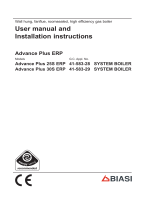
1.1 Overview
Fig. 1.1
1
2
3
1 Case front panel
2 Control panel
3 Control panel cover
1.2 Control panel
4 C.H. circuit temperature and pressure
gauge
5 Lock-out signal lamp
6 Lockout reset button
7 Function selector and C.H. temp. con-
trol knob
8 Service knob
9 Appliance operation lights
The service knob 8 is useless for the normal
operation of the boiler.
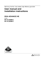
1.3 Isolation valves
Fig. 1.2
13
12
11
10
10 Condensate drain pipe
11 C.H. return valve
12 Gas inlet valve
13 C.H. ow valve
1.4 Technical data
For detailed technical data see sections
"Technical Data" on pag. 18 or pag. 21.
9 8 7 6 5 4
Fig. 1.3

- 9 -
USE
APPLIANCE DESCRIPTION
1.5 Operation lights
Three lights (9 in Fig. 1.3) give detailed indi-
cation regarding the operation of the boiler.
The following table gives the relationship
between each of the possible light combina-
tions and their meaning.
A short pulse every 4
seconds: stand-by con-
dition
Function selector in
position.
Anti-freeze system ac-
tive
1 second pulse every 2
seconds: normally op-
erating boiler. Function
selector in
position
C.H. operation
Frost protect operation
Faulty C.H. tempera-
ture
probe NTC
Faulty ue temperature
probe NTC
Faulty primary circuit
(no water or low C.H.
pressure)
Faulty primary circuit
(absence of ow)
Faulty air pressure
sensor
Lack of burner ignition
(no ignition signal from
the full sequence igni-
tion device)
Safety thermostat lock
out
Flue temperature probe
NTC lock out
Flame detection error
Other faults
Lack of power supply
or faulty electr. control
p.c.b.
Meaning of symbols:
Lamp OFF
Lamp ON
Flashing lamp, alone or simulta-
neously with an other lamp
Flashing lamp, alternate with an-
other lamp
If the lights combination observed is not
included in the above table a fault may be
indicated.
Reference should be made to the following
table.
In this case switch off the boiler, as de-
scribed in section "Switching off" to page 12
and call a competent and responsible Ser-
vice Engineer.

- 10 -
USE
INSTRUCTIONS FOR USE
2 INSTRUCTIONS FOR USE
2.1 Warnings
Biasi UK Ltd support the Benchmark
initiative. The Benchmark Checklist is
located at the back of this manual and
should be completed by the Installing/
Commissioning Engineer and handed
over to the User for future reference by
other visiting Engineers. Also included
is the Service Interval Record card that
should be completed by the Service
Engineer following the annual service
maintenance of the boiler and system.
All Gas Safe Registered Installers carry
a Gas Safe ID card, and have a registra-
tion number. Both should be recorded
in your Benchmark Checklist. You can
check your Installer is registered by call-
ing Gas Safe direct on 0800 408 5500,
or go on line at www.GasSafeRegister.
co.uk.
In order to guarantee safety and correct op-
eration, it is essential that all the tests are
carried out by a competent and responsi-
ble service engineer before lighting up the
boiler.
The tests are described in the installation
instructions in section 7 commissioning.
Ensure that the C.H. circuit is regularly lled
with water (even if the boiler is only used for
D.H.W. supply) checking that the pressure
indicated on pressure gauge 4 is not lower
than that shown in Fig. 2.2.
If the pressure reading on the pressure
gauge is below that shown in Fig. 2.2, then
the system will require topping up.A lling
loop is normally provided by the Installer for
this purpose.
If you are in any doubt regarding this
procedure you are advised to contact
your Installer or an Approved Engineer.
This appliance is provided with a built in
anti-freeze system that operates the boiler
when the temperature is below 5 °C.
Therefore, when the boiler is not lit or used
in cold weather, with consequent risk of
freezing do not switch off the boiler at the
fused spur isolation switch or close the
gas inlet cock.
When you do not expect to use the boiler
for a long period and the boiler is not to be
used for frost protection then follow the in-
structions given in section "Switching off" to
page 12.
2.2 Relling procedure
• Isolate the boiler from the electrical sup-
ply at the fused spur. Reconnect the lling
loop as demonstrated in Fig. 2.1.
Fig. 2.1
Control valve
Double
check valve
Temporary
connection
Supply pipe
(cold water inlet)
Control valve
C.H. return pipe
• Open the valves of the lling loop and
watch the gauge until it reaches normal
lling pressure as shown in Fig. 2.2.
Fig. 2.2
Normal
lling
pressure
4
• Close the valves and remove the lling
loop.
If you experience any difculty with the
operation of the boiler, switch off the
boiler immediately at the fused spur iso-

- 11 -
USE
INSTRUCTIONS FOR USE
lation switch and contact your Installer
or an approved Service Engineer.
Air introduced into the boiler during this ll-
ing process will vent through the automatic
air purger tted to the boiler. You may also
nd it necessary to vent air from your radia-
tor circuit using your radiator key, however
be aware that excessive venting will cause
the pressure in the system to drop.
Always ensure that the pressure gauge is
set at the required pressure.
2.3 Ignition
• Check that the valves located in the lower
part of the boiler are open Fig. 2.3.
Fig. 2.3
Open position
• Turn on the electricity supply to the boil-
er switching on the fused spur isolation
switch. The appliance operation light
9 (Fig. 2.4) will ash every 4 seconds
(stand-by condition).
• To operate the boiler, position the function
selector 7 as in Fig. 2.4. The appliance
operation light 9 will ash every 2 seconds
(operating boiler).
Fig. 2.4
9
7
2.4 C.H. circuit temperature
The output temperature of C.H. water is ad-
justable from a minimum of about 40°C to a
maximum of about 85°C (Fig. 2.5), by turn-
ing the function selector (7).
Adjustment of C.H. output on the boiler is
automatic.
Fig. 2.5
Minimum
Maximum
The greatest output pre-set in the factory
can, however, be reduced in level accord-
ing to actual system requirements; this does
not affect the maximum output in D.H.W.
operation.
Such adjustments must be carried out by a
qualied person; therefore we advise you to
contact your installer or Service Agent.
Adjustment of the boiler temperature alters
the gas ow at the burner according to the

- 12 -
USE
INSTRUCTIONS FOR USE
thermal demand in the system. So it is usual
to see the burner lit at the minimum level for
more or less long periods.
Adjustment
In order to achieve optimal settings for econ-
omy and comfort, we recommend adjusting
the operating temperature of the C.H. water
according to the outside temperature, posi-
tioning the knob as follows:
Fig. 2.6
From 5 to 15 °C
Between
- 5 and +5 °C
Lower
than - 5 °C
Your qualied installer will be able to rec-
ommend the most suitable adjustment for
your system. The temperature and pres-
sure gauge (4, Fig. 1.3 on page 8) will al-
low you to check that the set temperature
is obtained.
2.5 Switching off
To turn the boiler off set the function selec-
tor 7 to the position shown in Fig. 2.7.
Fig. 2.7
9
7
The appliance operation light 9 will ash
every 4 seconds.
When you do not expect to use the boiler for
a long period:
• Switch off the electricity supply to the boil-
er, by means of the fused spur isolation
switch;
• Shut off the gas supply cock 12 and the
valves for the water circuits tted under
the boiler (Fig. 2.8).
• Empty the water circuits, if necessary,
as shown in section General access and
emptying hydraulic circuits in the service
manual.
Fig. 2.8
12
Closed position

- 13 -
USE
USEFUL ADVICE
3 USEFUL ADVICE
3.1 Central Heating
For reasonably economical service install a
room thermostat. Never shut off the radiator
in the area where the room thermostat is in-
stalled.
If
a
radiator (or a convector) does not heat up,
check that no air is present in it and that its
valve is open. If the ambient temperature is
too high, do not alter the radiator valves. Re
-
duce the central heating temperature instead
by means
of the room thermostat and the
function selector (7 in Fig. 3.1).
Fig. 3.1
7
3.2 Frost protection
This appliance is provided with a built in anti-
freeze system that operates the boiler when
the temperature is below 5 °C
Therefore, when the boiler is not lit and used
in cold weather, with consequent risk of freez
-
ing do not switch off the boiler at the fused
spur isolation
switch or close the gas inlet
cock.
3.3 Condensate drain
The condensate drain must not be modied
or blocked. Blockage of the condensate drain,
caused by debris or freezing, can cause auto-
matic shutdown of the boiler.
If
freezing
is suspected and the pipe run is ac-
cessible an attempt may be made to free the
obstruction by
pouring hot water over the ex-
posed pipe an cleaning any blockage from the
end of the pipe.
If this
fails to remedy the problem the assis-
tance of a Gas Safe Registered Installer or in
IE a competent person should be sought.
3.4 Periodic maintenance
For efcient and continuous operation of the
boiler, it is advisable to arrange maintenance
and cleaning by an Authorised Service Centre
Engineer, at least once a year.
During the service, the most important com
-
ponents of the boiler will be inspected and
cleaned. This
service can be part of a main-
tenance contract.
In particular
, you are advised to have the fol-
lowing checks carried out:
•
primary heat exchanger;
• burner;
• exhaust fume duct and ue;
• pressurisation of the expansion tank;
• lling up of the central heating circuit;
• bleeding of air from the central heating sys
-
tem;
•
general check of the appliance’s operation.
Please refer to the servicing information on
section "MAINTENANCE" on page 50.
3.5 External cleaning
Before carrying out any cleaning,
disconnect the appliance from the
electrical mains, using the fused
spur isolation switch tted adja-
cent to the appliance.
To
clean the external panels, use a cloth
soaked in soapy water. Do not use solvents,
abrasive powders or sponges.
Do not carry out cleaning of the appliance
and/or its parts with readily ammable sub
-
stances (for example petrol, alcohols, naph-
tha, etc.).

- 14 -
USE
USEFUL ADVICE
3.6 Operational faults
If the lock-out signal lamp comes on
This indicates that the safety lock-out 5 (Fig.
3.2) has stopped the boiler.
To re-start the boiler, it is necessary to press
the boiler reset button 6 (Fig. 3.2).
Fig. 3.2
6
5
For the rst lighting up and following mainte-
nance procedures for the gas supply, it may
be necessary
to repeat the resetting operation
several times so as to remove the air present
in the pipe work.
After ve consecutive resetting attempts the
reset button is inhibited. To restore its func
-
tion it is necessary to switch the boiler off and
on from
the electrical mains, using the fused
spur isolation switch tted adjacent to the ap-
pliance.
Safety
lock-out
may occur even in case of a
blockage of the condensate drainage (e.g.
plugged drain pipe).
It is advisable to check the condensate drain
-
age pipe and traps for cleanness.
In this case and in case of persis-
tent lock-out call a competent and
responsible Service Engineer.
If noises due to air bubbles are heard dur-
ing operation...
Y
ou
should check that the pressure on the
temperature and pressure gauge (Fig. 2.2 on
page 10) is not below the correct setting.
If required, top up the system correctly, as de
-
scribed in the section "Rellin
g procedure" to
page 10.
Bleed any air present in the radiators, if nec-
essary.
If the pressure on the temperature and
pressure gauge has gone down...
It is necessary to top up the appliance with
water again, so as to raise the pressure to
an adequate level as described in the section
"Relling procedure" to page 10. If topping
up with water has to be done very frequently,
have the system checked for leaks.
If water comes out of the pressure relief
valve
Check on the temperature and pressure
gauge that the pressure in the central heat
-
ing circuit is not close to 3 bars. In this case,
temperature rise
in the circuit can cause the
pressure relief valve to open.
So that this does not happen and to decrease
the pressure to a normal value, it is advisable
to vent some of the water in the appliance
through the bleed valves present in the radia
-
tors.
If water should occasionally leak from the
boiler
...
Shut
off the valves positioned under the boiler
(Fig. 2.8 on page 12) and call an Authorised
Service Centre Engineer.
If the left appliance operation light 9 (Fig.
3.3) ashes very quickly the boiler is de
-
tecting a fault.
Fig. 3.3
9
7
In this case or in case of problems
other than those mentioned here,
switch off the boiler, as described
in section "Switching off" to page
12 and call a competent and re-
sponsible Service Engineer.

- 15 -
INSTALLATION
TECHNICAL INFORMATION
4 TECHNICAL INFORMATION
4.1 Overview
Fig. 4.1
17 19
31
27 26 23
29
28
24
16
20
25 21
30
18 14 15
22
32
33

- 16 -
INSTALLATION
TECHNICAL INFORMATION
4.2 Main diagram
Fig. 4.2
10 Condensate drain pipe
11 C.H. return valve
12 Gas inlet valve
13 C.H. ow valve
14 Fan
15 Air pressure sensor test points
16 Air pressure sensor
17 Flue temperature probe NTC
18 Condensing heat exchanger
19 Safety thermostat
20 C.H. temperature probe NTC
21 Condensate trap
22 Main circuit drain valve
23 Automatic air purger valve
40
41
18
30
14
16
24
27
25
12 11
39
10
13
38
21
23
29
20
35
26
31
33
17
19
37
36
34
22
28

- 17 -
INSTALLATION
TECHNICAL INFORMATION
24 Pump
25 C.H. pressure relief valve
26 Modulation gas valve
27 Primary circuit pressure switch
28 Combustion chamber over heat
29 Flame-detecting electrode
30 Burner
31 Ignition electrodes
32 Combustion chamber
33 Primary heat exchanger
34 Modulation operator
35 Gas valve outlet pressure test point
36 Gas valve inlet pressure test point
37 C.H. expansion tank
38 By-pass valve
39 Fan pressure connection
40 Flue outlet pipe
41 Air intake pipe

- 18 -
INSTALLATION
TECHNICAL INFORMATION
4.3 Technical data mod. Riva Plus
HE 24S ERP
Heat input
Nominal net
(A)
(C.H.)
kW 25,0
BTU/h 85304
Nominal gross
(B)
(C.H.)
kW 27,8
BTU/h 94687
Minimum net
(A)
C.H.
kW 7,5
BTU/h 25591
Minimum gross
(B)
C.H.
kW 8,3
BTU/h 28406
Useful output
Maximum (C.H.)
kW 24,4
BTU/h 83256
Minimum (C.H.)
kW 7,3
BTU/h 24909
Maximum condensing (C.H.)
kW 26,3
BTU/h 89739
Minimum condensing (C.H.)
kW 7,8
BTU/h 26615
Central heating
Min/Max ow temperature settings* °C 50-85
Minimum return temperature °C 40
Maximum pressure
kPa 250
bar 2,5
Minimum pressure
kPa 30
bar 0,3
Available head (in 1000 l/h)
kPa 25
bar 0,25
Seasonal efciency G20 % 88,1
Seasonal effciency G30 G31
(C)
% 89,1
* to the minimum useful output
Gas supply pressures
Gas Pa mbar
Natural G20
Nom 2000 20
Min 1700 17
Max 2500 25
Butane G30
Nom 2900 29
Min 2000 20
Max 3500 35
Propane G31
Nom 3700 37
Min 2500 25
Max 4500 45
1 mbar approximately equals 10 mm H
2
O
Max. gas pressures at the burner
Natural G20
Pa 1340
mbar 13,4
Butane G30
Pa 2760
mbar 27,6
Propane G31
Pa 3550
mbar 35,5
Min. gas pressures at the burner
Natural G20
Pa 140
mbar 1,4
Butane G30
Pa 280
mbar 2,8
Propane G31
Pa 350
mbar 3,5
Ignition gas pressures at the burner
Natural G20
Pa 850
mbar 8,5
Butane G30
Pa 2110
mbar 21,1
Propane G31
Pa 2700
mbar 27,0
1 mbar approximately equals 10 mm H
2
O

- 19 -
INSTALLATION
TECHNICAL INFORMATION
Gas rate maximum – C.H.
Natural G20 m
3
/h 2,65
Butane G30 kg/h 1,97
Propane G31 kg/h 1,94
Gas rate minimum – C.H.
Natural G20 m
3
/h 0,79
Butane G30 kg/h 0,59
Propane G31 kg/h 0,58
Gas restrictors references N°
Ø mm
/100
Natural G20 12 120
Butane G30 12 77
Propane G31 12 77
Electrical data
Voltage V~ 230
Frequency Hz 50
Nominal Power consumption W 79
Minimum Power consumption W 65
Stand-by Power consumption W 3
Protection degree IPX4D
External fuse rating A 3
Internal fuse rating A
N° 2 - 2
AF
Flue design
Boiler type
C12 C32 C42 C52 C82
ø Coaxial mm 60/100
ø Twin split pipes mm 80/80
ø Roof mm 60/100
ø Roof mm 80/125
Nominal heat ow rate
(A) (E)
kW 25,0
Exhaust temperature
(E)
°C 60,0
Mass ow rate
(E)
kg/s 0,0128
Flue gas gures
Nominal heat input
(A) (E)
kW 25,0
CO
2 content with gas G20 % 7,9
O
2 content with gas G20 % 6,8
CO content with gas G20 ppm 52,0
Exhaust temperature
(E)
°C 60,0
NOx class 2,0
Weighted NOx ppm 94
CO
2 contents
Nominal heat input
(A) (E)
kW 25,0
CO
2 content with gas G20 % 7,9
CO
2 content with gas G30 G31 % 9,1
Minimum heat input
(A) (E)
kW 7,5
CO
2 content with gas G20 % 3,9
CO
2 content with gas G30 G31 % 4,5
Other specications
Height mm 803
Width mm 400
Depth mm 350
Weight (dry) kg 35,5
Water volume in the boiler (up to 1
bar)
l (kg) 1,4
(A)
referred to the net caloric value at 15°C and
1013,25 mbar: G20 = 34,02 MJ/m
3
- G31 = 46,34 MJ/
kg
(B)
referred to the gross caloric value at 15°C and
1013,25 mbar: G20 = 37,78 MJ/m
3
- G31 = 50,37 MJ/
kg
(C)
The value is used in the UK Government’s Standard
Assessment Procedure (SAP) for energy rating of
dwellings. The test data from which it has been calcu-
lated have been certied by a notied body.
(D)
Values subject to tolerance
(E)
Values refer tests with a 1 m ue working at the
nominal heat input
(1208)

- 20 -
INSTALLATION
TECHNICAL INFORMATION
Model(s): Riva Plus HE 24S ERP
Condensing boiler: Yes
Low-temperature boiler (**): No
B1 boiler: No
Cogeneration space heater: No If yes, equipped with a supplementary heater: -
Combination heater: No
Item Symbol Value Unit Item Symbol Value Unit
Rated heat output P
rated
24 kW
Seasonal space heating
energy efciency
η
s
89 %
For boiler space heaters and boiler combination heat-
ers: Useful heat output
For boiler space heaters and boiler combination heaters:
Useful efciency
At rated heat output and
high-temperature regime (*)
P
4
24,4 kW
At rated heat output and
high-temperature regime (*)
η
4
87,7 %
At 30% of rated heat output
and low-temperature regime
(**)
P
1
7,9 kW
At 30% of rated heat output
and low-temperature regime
(**)
η
1
95,4 %
Auxiliary electricity consumption Other items
At full load elmax 0,079 kW Standby heat loss P
stby
0,098 kW
At part load elmin 0,065 kW
Ignition burner power con-
sumption
P
ign
- kW
In standby mode P
SB
0,003 kW Annual energy consumption Q
HE
79 GJ
Sound power level, indoors L
WA
48 dB
Emission of nitrogen oxides NO
x
166
mg/
kWh
For combination heaters:
Declared load prole
Water heating energy ef-
ciency
η
wh
%
Daily electricity consumption Q
elec
kWh Daily fuel consumption Q
fuel
kWh
Annual electricity consump-
tion
AEC kWh Annual fuel consumption AFC GJ
Contact details See manual cover
(*) High-temperature regime means 60°C return temperature at heater inlet and 80°C feed temperature at heater
outlet.
(**) Low temperature means for condensing boilers 30°C, for low-temperature boilers 37°C and for other heaters
50°C return temperature (at heater inlet).
/