Hydro Systems ARB6636TAW Installation guide
- Type
- Installation guide

1
INSTALLATION INSTRUCTIONS
USER MAINTENANCE INSTRUCTIONS
INSTALLATION INSTRUCTIONS
•
Read all instructions before proceeding with installation.
•
Inspect the tub before installation. If any damage or defects are found, do not install the tub. If the tub is not the right
size, model or color do not install the tub. Contact tech support at 661-775-0686 or email [email protected]
•
INSTALLATION OF A THE MAESTRO COLLECTION BATHTUB MUST MEET ALL APPLICABLE CODES AND REGULATIONS.
IMPORTANT-
All tub and systems are thoroughly tested and inspected at the factory prior to shipment. However, it is possible for
damage to occur during shipment and installation. Such damage is not always readily visible. To maintain the warranty, it
is important to water test the tub, integral overflow and thermal system a minimum of 30 minutes for leaks prior to rough
installation before enclosing the tub. Hydro Systems is not responsible for the cost to remove/reinstall a tub.
CARE AND CLEANING-
To assure a long lasting “like new” look on your Maestro Collection bathtub we recommend the following easy
care procedures:
1) For normal maintenance, especially after use, clean with a soft cloth or sponge and a mild soap or liquid detergent.
2) DO NOT USE abrasives such as scouring compounds, scouring pads, steel wool or harsh chemicals on your
Hydro Systems bathtub. For deeper stains, hard scale deposits or any other cleaning or maintenance problem,
contact your Hydro Systems dealer.
THE MAESTRO COLLECTION
INSTRUCTIONS PERTAINING TO A RISK OF FIRE,
ELECTRIC SHOCK, OR INJURY TO PERSONS.
1. DANGER: To reduce the risk of injury, do not permit children to use this unit unless they are closely supervised at all times.
2. Use this unit only for its intended use as described in this manual. Do not use attachments not recommended by the
manufacturer.
3. Never drop or insert any object into any opening.
4. Do not operate this unit without the cover over the suction fitting.
5. The unit must be connected only to a dedicated electrical supply circuit that is protected by a Ground Fault Circuit
Interrupter (GFCI). The GFCI must be provided by the installer and should be tested on a routine basis by the homeowner.
To test the GFCI push the test button. The GFCI should interrupt power. Push the RESET button. Power should be restored.
If the GFCI fails to operate in this manner there is a ground current fault, indicating the possibility of an electric shock.
Do not use the tub. Disconnect the power and have the problem corrected by a qualified service representative. Re-test the
GFCI. Only when it is operating properly may the whirlpool tub be used.
IMPORTANT SAFETY INSTRUCTIONS
WARNING: WHEN USING YOUR HYDRO SYSTEMS BASIC PRECAUTIONS SHOULD BE FOLLOWED, SEE BELOW
SAVE THESE INSTRUCTIONS FOR LATER REFERENCE
READ AND FOLLOW ALL INSTRUCTIONS
GLOSS FINISH
• Clean with mild dish soap and water, any non abrasive product to clean high-gloss counter surfaces will work.
• Remove dust with a soft damp cloth, for example; microfiber or calico cloths.
• Clean oil, paint, ink or grease with rubbing alcohol and dry with a soft cloth.
• Avoid using abrasive cleaners, it is not safe to use these on your glossed product.
• Please do not use any sharp objects because that might result in scratching the surface of the tub.
Please do not use anything else other than what was instructed. Improper use can result in damage to the tub or
its finish and may void the warranty. Keep in mind, if you do end up damaging the tub, scratches can usually be
removed, buffed or polished out by an Authorized Hydro Systems Service Agent.
CLEANING INSTRUCTIONS
You will need to know the bathtub serial number attached
to your warranty card and also located on the bottom side
of the bathtub when contacting Hydro Systems.

FREESTANDING INSTALLATION
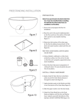
PREPARATION
Clean, level, and prepare the floor for installation.
Place the unit in the exact installed position on the floor
and trace the outline of the bath with a pencil or any
erasable marking (Figure 1). Templates for Freestanding
bathtubs come with the tub.
Determine the location of the drain pipe, on the floor
by taking measurements of the drain and waste location
underneath the unit (Figure 2).
3
4
5
1
2
FIGURE 1
Using a blanket, cardboard, or other clean protective
surface, turn the unit on its side so that the unit is
properly supported during drain installation.
Clean the drain hole area in preparation of setting the
strainer. The area should be dry and free of any debris.
2
INSTALL DRAIN HARDWARE
Apply plumbers putty around the Drain Body and pass it
through the drain hole (Figure 3).
Slide the rubber washer over the drain body.
Attach the drain Body to the ABS/ PVC Shoe fitting and
tighten until the Gasket has created a seal with the bottom
of the bathtub. DO NOT OVERTIGHTEN (Figure 4).
6
7
8
9
FIGURE 3
PREPARE TAIL PIECE
Apply rubber gasket and slide it over the
bottom of the Drain Body (Figure 5)
Install 1 ½"rubber slip gasket over the drain body.
Thread in shoe.
Glue shoe to tail piece.
10
12
11
FIGURE 5
tail piece (shoe)
FIGURE 4
FIGURE 2

3
FIGURE 8
FIGURE 6
FIGURE 7
FREE STANDING TUBS
GENERAL INFORMATION
•
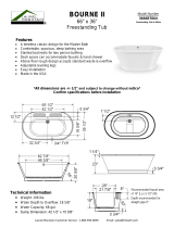
Rough In Dimensions – For critical dimensions, we suggest taking the measurements of the actual tub on site.
All printed specifications are +/- ½ inch and subject to change without notice.
•
Base –the tub must be level
BASIC INSTALLATION PROCEDURE
•
Determine final location of the tub. Tub will sit on top of finished flooring.
•
Ensure location is structurally sound, flat and level.
•
Align the tub in a manner that the drain lines up with the P-trap in the floor. DO NOT LET THE TUB REST ON
THE DRAIN PLUMBING.
•
Check the tub for level. It must be level end to end and side to side.
•
Caulk the gap between the skirt and the floor.
SUPPLEMENTAL INSTALLATION INFORMATION
TOWER
A Tower can be added to any of our
Maestro Bathtubs allowing you to
use traditional Roman faucets.
WASTE AND OVERFLOW
The Maestro Collection offers integral waste and overflow
on all models because of the the limited space between the
inner and outer tub shells. Use care when selecting your drain
kit. The Maestro Collection offers toe tap hardware standard.
Then apply a bead of tub and tile caulk or silicone
around the edge of the base (Figure 8).
Adjust legs to a height of
1
/
8
" max below skirt.
COMPLETE BATHTUB INSTALLATION
Fill tub with water to the overflow and then drain the tub while
inspecting the waste connections below the floor for leaks.
Access from below will be necessary for this step (Figure 9).
Apply generous bead of adhesive or silicone to the
bottom of the tub supports and feet. (Figure 6).
Carefully set tub into position (Figure 7) and connect
the drain hardware (previously installed).
INSTALL BATHTUB
FIGURE 9
14
15
16
13
17

4
THERMAL AIR
ELECTRICAL REQUIREMENTS:
WARNING: When using electrical products, basic precautions should always be followed, including the folowing:
DANGER: RISK OF ELECTRICAL SHOCK. Connect only to a circuit protected by a ground fault circuit interrupter. Grounding is
required. All electrical connections should be made by a licensed electrician. Installation of Hydro Systems bathtubs must meet
all applicable codes and regulations.
– 1 HP Blower - A dedicated 120v 20 amp GFCI protected electrical circuit is requirred for tubs with the standard 1 HP 120v Blower.
• Remote Mounting Blower – Due to the limited space between the inner and outer shell on all of The Maestro
Collection Freestanding tubs, the blower must be remote mounted. In addition to the air pipe there are two
electrical connections between the tub and the blower. Both connections and the air pipe exit through the bottom
end of the bath. It is always desirable to remote mount the air blower as close to the tub as possible to minimize loss
of heat. Pipe insulation may be used on the inlet air line to minimize heat loss.
• It is not recommended that the blower be mounted over 8 feet away from the tub. The supplied wiring
between the tub and the blower is approximately 10 feet long.
• Remote blower locations – There are several locations where the blower can be located. There must be a GFCI
electrical outlet within 2 feet of the blower. The blower is approximately 9.25 inches long and 8 inches in diameter
and 5” high. Substantial ventilation is required to keep the blower from overheating and to supply the large volume
of air being sent to the tub. Never wrap insulation around the blower as this will cause the equipment to fail. The
best location is directly below the tub in the floor joists. This location keeps the distance short and offers easy access
from below. If the room below has a finished ceiling, there are many fixtures such as HVAC return that can be used to
camouflage the access panel in the ceiling. Other possible locations include an adjacent closet, vanity or a same
level attic. Every home is different and there may be other desirable locations. Keep in mind that the blower must be
accessible for any future servicing.
• Remote Blower Kit – If the blower is not mounted directly adjacent to the tub, a remote blower kit will be required.
The kit consists of: extension pipe, couplings and cable. Please indicate the necessary length of pipe and cable
required.
FIXTURES
•
No Fixtures can be mounted on the tub deck. Floor and wall-mounted fixtures are required.
•
Wall-Mounted – The position of the tub and the reach of the spout are critical. Pay special attention to the spout
reach when choosing your fixtures. Be careful to ensure the spout will extend out far enough to clear the tub deck
and the falling water will not hit too high up the side wall of the tub and splash.
•
Floor-Mounted – Some freestanding fixtures must be anchored to the tub drain for stabilization.
MAESTRO COLLECTION
99
/
9
WARRANTY
This warranty is effective for all Maestro Series Hydro Systems Soaking and Thermal Air tubs manufactured after September 1st, 2009, and is
in lieu of all other warranties.
99 Year Warranty on Combination/Whirlpool/Thermal Air/Tub Shell
Hydro Systems, Inc. warrants to the original purchaser of the Combination, Whirlpool or Thermal Air, that the shell will maintain its
structural integrity and configuration and will be free of water loss due to a defect in the tub shell for a period of 99 years from the purchase date.
The warranty covers the tub shell against defects in materials and workmanship. The warranty does not apply to any other component or plumbing
component, as they are covered under separate warranties.
9 Year Warranty on Equipment, Components & Controls
Hydro Systems, Inc. warrants to the original purchaser of the Thermal Air or LED Lighting Tub that all support equipment, controls and plumbing
components (excluding plumbing fittings and piping) for a period of 9 years from the purchase date. Limited labor is covered
for the first 3 years of ownership, starting from the date of purchase and not the date of installation.
3 Year Warranty on Plumbing Equipment & Labor
Hydro Systems, Inc. warrants to the original purchaser of the Combination, Whirlpool, Thermal Air or Soaking Tub that the plumbing fittings and
equipment will not leak water due to defects in materials or workmanship for a period of 3 years from the purchase date. Limited labor for any repair
is covered for a period of 3 years for the labor aspect of the warranty only.
This limited warranty does not include any other items not manufactured by HYDRO SYSTEMS, INC. HYDRO SYSTEMS, INC. does not assume liability
for the finish or the wearing quality of any plated product. No dealer or other person has any authority to make any warranties or representations
concerning HYDRO SYSTEMS, INC. or its products. Accordingly, HYDRO SYSTEMS, INC. is not responsible for any such warranties or representations.
THERE ARE NO WARRANTIES BEYOND THE DESCRIPTION ON THE FACE HEREOF. NO WARRANTY OF MECHANTABILITY, FITNESS, NOR OTH-
ER WARRANTY (WHETHER EXPRESS, IMPLIED OR STATUTORY) IS MADE BY HYDRO SYSTEMS, INC., EXCEPT THAT IT WARRANTS THE GOODS
TO BE FREE FROM DEFECTS IN MATERIALS AND WORKMANSHIP IN NORMAL USE AND SERVICE AS DESCRIBED ON THE FACE HEREOF.
WARRANTY OBLIGATIONS OF HYDRO SYSTEMS, INC.:
Should a defect in workmanship and/or material in any item cover by this warranty become evident during the term of the warranty, then upon the
consumer following the procedures set forth below, HYDRO SYSTEMS, INC. at its opinion, will repair or replace such item at its own cost and
expense. HYDRO SYSTEMS, INC. is not, however, responsible under this warranty for any cost of shipping or transportation or the equipment
or parts thereof to or from the Service Department. Also, HYDRO SYSTEMS, INC. is not liable for any loss of time, inconvenience, incidental expenses
such as telephone calls, labor or material charges incurred in connection with the removal or the replacement of the equipment, or any other
incidental or consequential damages, unless otherwise prohibited by applicable State law.
-
 1
1
-
 2
2
-
 3
3
-
 4
4


Hydro Systems ARB6636TAW Installation guide
- Type
- Installation guide
Ask a question and I''ll find the answer in the document
Finding information in a document is now easier with AI
Related papers
-
Hydro Systems REG7232ATO-WHI-RH User guide
-
-
-
-
Hydro Systems ROD6132MTO-WHI Installation guide
-
-
Hydro Systems LIB6332MTO-WHI Installation guide
-
Hydro Systems STO7242ATOB Installation guide
-
Hydro Systems SYD6030TOBLWPCL Installation guide
-
Hydro Systems FUJ4040GTO-WHI User manual
Other documents
-
 Laurel Mountain 6636BT064 Dimensions Guide
-
Dyconn WTM02803-NM Operating instructions
-
Vanity Art VA6610 Installation guide
-
 Wyndham Collection WCOBT100559 Installation guide
-
MTD Vanities MTD-MAL-60 Installation guide
-
Stivier 21S0105-60 User manual
-
Wyndham Collection WCOBT101567BNTRIM Installation guide
-
Universal Tubs HD3468SDX Installation guide
-
Duravit GK5900008 Specification Manual
-
 Kingston Brass HVTDE673123S Installation guide


