Page is loading ...

!
!
Failure to follow these instructions can damage the product or cause a hazardous
condition. Disconnect power during the installation of this product. All wiring must conform
to local codes and ordinances. We strongly recommend that any installation or servicing
be performed by a qualified technician. This thermostat is designed for use with 24VAC
systems only. For additional support contact Pelican Technical Support at 888-512-0490
or email [email protected]
WARNING
!
NEVER INSTALL THE PELICAN THERMOSTAT ENCLOSED IN METAL.
WIRELESS CANNOT COMMUNICATE THROUGH METAL.
Installation Guide
Internet
Programmable Thermostat
with Humidity
TS200H
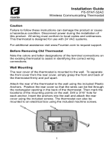
Thermostat Terminal Designations
Conventional Control Heat Pump Control
Before Removing the Old Thermostat!
Note the wire colors and letter designations of the existing thermostat to
assist in identifying the correct wiring connections to the TS200H.
D
C
R
DATA
COMMON
24VAC (HEAT)
24VAC (COOL)
Rc
Y
W
G
COOL STAGE 1
HEAT STAGE 1
FAN
W2
Y2
Hu
Dh
HEAT STAGE 2
COOL STAGE 2
HUMIDIFY
DE-HUMIDIFY
D
C
R
DATA
COMMON
24VAC
24VAC
Rc
Y
W
G
COMPRESSOR STAGE 1
REVERSING VALVE (O/B)
FAN
W2
Y2
Hu
Dh
AUXILIARY HEAT
COMPRESSOR STAGE 2
HUMIDIFY
DE-HUMIDIFY

TS200H Mounting and Assembly
1
Mount thermostat rear cover to the wall.
2
2
Old thermostat
Remove old thermostat
Option One:
Mark mounting holes
drill two 3/16” holes in
wall. Insert drywall anchors
and use provided sheet metal
screws to attach rear
cover to wall.
Rc
CD R
R
C
D
Y W G W Y2 2 Hu Dh
Pelican
Wireless Systems
Wiring Module
Model: WM700
Power: 24-30 VAC
PelicanWireless.com
Grasp front and back of thermostat and firmly pull apart.
Option Two:
Mount rear cover on
horizontal two gang
electrical box. Use
included machine
screws.

Rc
CD R
R
C
D
Y W G W Y2 2 Hu Dh
Pelican
Wireless Systems
Wiring Module
Model: WM700
Power: 24-30 VAC
PelicanWireless.com
Align three pin connector from thermostat front cover to
three pin connector on rear cover. Push front cover onto
rear cover until secure.
Thermostat Front Cover Thermostat Rear Cover
Pelican Wilreless Systems
U
L
LISTED
ENERGY MGMT EQPT
E471330
3
3
TS200H Mounting and Assembly
The thermostat contains an internal locking mechanism to secure the
front cover to the rear cover. This is intended to keep untrained
individuals from tampering with the power and thermostat wire.
To engage the lock, assemble the thermostat and insert a 7/64" Allen
wrench (not included) into the key hole on the top of the thermostat.
Rotate clockwise until reaching the stop to secure. Rotate
counter-clockwise until reaching the stop to release.
7/64" Allen wrench
unlock rotation
lock rotation
Optional Tamper Resistant Lock

4
Conventional Wiring Guide
CD R Rc Y W G W2 Y2 Hu Dh
Fan Circuit
Heat Circuit
Compressor Relay
24 VAC Power
24 VAC Common
Use 18 gauge unshielded
cable from thermostat to
the equipment.
1
5 Wire, 24VAC Conventional 1 stage cooling with
1 stage heat
1
For a Two Transformer System – remove jumper between R and Rc.
Connect the 24VAC power for energizing the unit’s Compressor to
thermostat’s (R) terminal. Connect second 24VAC power to
thermostat’s (Rc) terminal.

CD R Rc Y W G W2 Y2 Hu Dh
5
6 Wire, 24VAC Conventional 1 stage cooling with
2 stage heat
2nd Stage Heat Circuit
Fan Circuit
1st Stage Heat Circuit
Compressor Relay
24 VAC Power
24 VAC Common
1
Conventional Wiring Guide
Use 18 gauge unshielded
cable from thermostat to
the equipment.
1
For a Two Transformer System – remove jumper between R and Rc.
Connect the 24VAC power for energizing the unit’s Compressor to
thermostat’s (R) terminal. Connect second 24VAC power to
thermostat’s (Rc) terminal.

CD R Rc Y W G W2 Y2 Hu Dh
6
6 Wire, 24VAC Conventional 2 stage cooling with
1 stage heat
2nd Stage Compressor
Fan Circuit
1st Stage Heat Circuit
1st Stage Compressor
24 VAC Power
24 VAC Common
1
Conventional Wiring Guide
Use 18 gauge unshielded
cable from thermostat to
the equipment.
1
For a Two Transformer System – remove jumper between R and Rc.
Connect the 24VAC power for energizing the unit’s Compressor to
thermostat’s (R) terminal. Connect second 24VAC power to
thermostat’s (Rc) terminal.

CD R Rc Y W G W2 Y2 Hu Dh
7
7 Wire, 24VAC Conventional 2 stage cooling with
2 stage heat
2nd Stage Compressor
2nd Stage Heat Circuit
Fan Circuit
1st Stage Heat Circuit
1st Stage Compressor
24 VAC Power
24 VAC Common
1
Conventional Wiring Guide
Use 18 gauge unshielded
cable from thermostat to
the equipment.
1
For a Two Transformer System – remove jumper between R and Rc.
Connect the 24VAC power for energizing the unit’s Compressor to
thermostat’s (R) terminal. Connect second 24VAC power to
thermostat’s (Rc) terminal.

CD R Rc Y W G W2 Y2 Hu Dh
8
7 Wire, 24VAC Conventional 1 stage cooling,
2 stage heat, and 2 fan speeds
1
For a Two Transformer System – remove jumper between R and Rc.
Connect the 24VAC power for energizing the unit’s Compressor to
thermostat’s (R) terminal. Connect second 24VAC power to
thermostat’s (Rc) terminal.
Conventional Wiring Guide
High Fan Speed
2nd Stage Heat Circuit
Low Fan Speed
1st Stage Heat Circuit
Compressor Relay
24 VAC Power
24 VAC Common
1
Use 18 gauge unshielded
cable from thermostat to
the equipment.

9
5 Wire, 24VAC Heat Pump 1 stage cooling with
1 stage heat
Heat Pump Wiring Guide
CD R Rc Y W G W2 Y2 Hu Dh
Fan Circuit
Reversing Valve
Compressor Relay
24 VAC Power
24 VAC Common
Use 18 gauge unshielded
cable from thermostat to
the equipment.

CD R Rc Y W G W2 Y2 Hu Dh
6 Wire, 24VAC Heat Pump 2 stage cooling with
2 stage heat
Heat Pump Wiring Guide
2nd Compressor Relay
Fan Circuit
Reversing Valve
1st Compressor Relay
24 VAC Power
24 VAC Common
(O/B)
Use 18 gauge unshielded
cable from the thermostat
to the equipment.
10

CD R Rc Y W G W2 Y2 Hu Dh
11
6 Wire, 24VAC Heat Pump 2 stage cooling,
1 stage heat and auxiliary/emergency heat
Heat Pump Wiring Guide
Auxiliary/Emergency Heat
Fan Circuit
Reversing Valve
1st Compressor Relay
24 VAC Power
24 VAC Common
(AUX)
(O/B)
Use 18 gauge unshielded
cable from the thermostat
to the equipment.

CD R Rc Y W G W2 Y2 Hu Dh
7 Wire, 24VAC Heat Pump 2 stage cooling,
2 stage heat and auxiliary/emergency heat
Heat Pump Wiring Guide
2nd Compressor Relay
Auxiliary/Emergency Heat
Fan Circuit
Reversing Valve
1st Compressor Relay
24 VAC Power
24 VAC Common
(O/B)
(AUX)
Use 18 gauge unshielded
cable from the thermostat
to the equipment.
12

CD R Rc Y W G W2 Y2 Hu Dh
7 Wire, 24VAC Heat Pump 1 stage cooling,
auxiliary/emergency heat, and 2 stage fan
Heat Pump Wiring Guide
High Speed Fan
Auxiliary/Emergency Heat
Low Speed Fan
Reversing Valve
Compressor Relay
24 VAC Power
24 VAC Common
(O/B) (AUX)
Use 18 gauge unshielded
cable from the thermostat
to the equipment.
13

CD R Rc Y W G W2 Y2 Hu Dh
24VAC Humidification Output
Humidifier Wiring Guide
Humidifier
Use 18 gauge unshielded
cable from the thermostat
to the equipment.
Hu
BOTH A HUMIDIFIER AND A
DEHUMIDIFIER CAN BE CONTROLLER BY
A SINGLE TS200H. DEHUMIDIFCATION
WIRING IS FOUND ON THE NEXT PAGE.
NOTE
!
14

Dehumidifier Wiring Guide
CD R Rc Y W G W2 Y2 Hu Dh
24VAC Dehumidification Output
Dehumidifier
Use 18 gauge unshielded
cable from the thermostat
to the equipment.
Dh
BOTH A DEHUMIDIFIER AND A
HUMIDIFIER CAN BE CONTROLLER BY A
SINGLE TS200H. HUMIDIFCATION WIRING
IS FOUND ON THE PREVIOUS PAGE.
NOTE
!
15

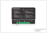
1. Loosen R and Rc terminal screws to remove jumper.
2. Loosen R, C, and D terminal screws on the Wiring Module
(WM700).
3. Gently slide the WM700 to the right and remove module
from the rear of the thermostat. The WM700 will slide out with
very little force.
CD R
Install WM700 inside HVAC unit Install TS200H in space
4. Mount the WM700 inside the HVAC unit. Follow the Wiring
Guide section (pg. 4 – 13) of this installation guide for direc-
tions on how to wire the WM700 to your type of HVAC unit.
Inside HVAC
unit
Rc
R
C
D
Y W G W Y2 2 Hu Dh
Pelican
WirelessSystems
Wiring Module
Model: WM700
Power: 24-30 VAC
PelicanWireless.com
Rc
R
C
D
Y W G W Y2 2 Hu Dh
Pelican
Wireless Systems
Wiring Module
Model: WM700
Power: 24-30 VAC
PelicanWireless.com
CD R
loosen
Remove WM700Loosen R, Rc, C, D Terminals
Optional Three Wire Installation
Some installations may have limited in-wall wire. In these cases, the TS200H can
accommodate the use of only three wires and still provide control over the entire
HVAC unit. To accomplish a three wire installation follow the steps outlined below:
16
Rc
R
C
D
Y W G W Y2 2 Hu Dh
Pelican
Wireless Systems
Wiring Module
Model: WM700
Power: 24-30 VAC
PelicanWireless.com

Rc
R
C
D
Y W G W Y2 2 Hu Dh
Pelican
Wireless Systems
Wiring Module
Model: WM700
Power: 24-30 VAC
PelicanWireless.com
WM700 INSTALLED
INSIDE HVAC UNIT
5. Use the existing in-wall 18 gauge unshielded wire to connect
the R, C, D terminals from the WM700 to the matching R, C, D
terminals at the thermostat
THE WIRING BELOW IS FOR A
STANDARD FIVE (5) WIRE
INSTALLATION. FOR DIFFERENT WIRING
OPTIONS FOLLOW THE WIRING GUIDES
FOUND IN THE PREVIOUS PAGES.
NOTE
!
Fan Circuit
Heat Circuit
Compressor Relay
24 VAC Power
24 VAC Common
CD R
THERMOSTAT
INSTALLED IN SPACE
Use 18 gauge unshielded cable
from WM700 to thermostat. Wire
can be up to 500 feet in length.
17

Inside Front Cover of Thermostat
Bottom of Thermostat
Thermostat Configuration
All configuration settings are made Online through the Pelican Web App. Each
thermostat will automatically join the Pelican Web App and will be listed both as a
notification and as a new thermostat under Admin. The thermostat is intially listed by
it’s serial number. Most configurable items can be left at their default settings. For
proper operation it is necessary to set the correct System Type (Conventional or
Heat Pump). If the Web App is not accessable, the thermostat’s System Type can be
set directly using the thermostat front keypad.
Setting System Type Using Thermostat Keypad
The thermostat can be placed into the correct system type (conventional or heat
pump) during the first minute after the unit has been powered on. If the thermostat
has been running for longer than one minute, remove the front cover of the
thermostat from the rear base and then re-attach. This will cause it to recycle the
power.
Within the first minute of the thermostat powered on, press and hold the up and
down arrows simultaneously for five seconds. This will place the thermostat in
configuration mode and the display will change to show one of the three possible
system type settings:
The system type can be changed by pressing the up arrow on the thermostat.
Once the correct setting is displayed, press any other button, the thermostat will
save the setting and return to normal operation.
Pelican Wireless Systems
Model No: TS200H
Serial No: 2S4-A71U
2S4-A71U
Thermostat Serial Number
Conventional System (Default)
Heat Pump
“W” Terminal Controls Reversing Valve.
Energized for Cool.
Heat Pump
“W” Terminal Controls Reversing Valve.
Energized for Heat.

This Page
Intentionally
Left Blank

37-0006 REV 2
Pelican Wireless Systems, 2655 Collier Canyon Rd. Livermore, CA 94551
Phone: 888.512.0490
Email: [email protected] Website: www.PelicanWireless.com
Pelican Wireless Systems.
All Rights Reserved.
For More Information on Pelican Wireless Systems
Please Visit: www.pelicanwireless.com
/